|
Our next stop on our London tour was to the London Postal Railway and Museum. Unbeknownst to many, London actually had an extensive subterranean rail system connecting different post offices and distribution points across the city. Mail would get loaded onto mail cars on this small gauge railroad and moved across the city by electric locomotives. The whole system would put you in the mind of an amusement park rail system in its size and the concept of design but the system had a role that was beyond mere amusement. The system served a vital role in keeping mail moving from different points through the city, coming and going, even during WW2. Even when bombing caused some disruptions, the system kept moving, and hence, the mail kept moving. Now, as modern tech does what it does, this whole system has been retired and a small portion of it has been restored for use as an actual amusement ride where the mail carts are set up for riders to sit in while the trail is piloted through sections of tunnel. The train stops at different stops that were underground distribution points that are now set up with projector presentations played over an intercom, talking about the history of the mail rail system. 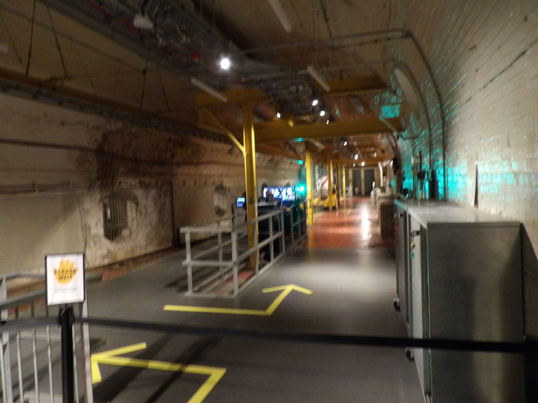 The rail station where riders come to get on the train where it goes around the tunnels, circling around and coming back to the station. 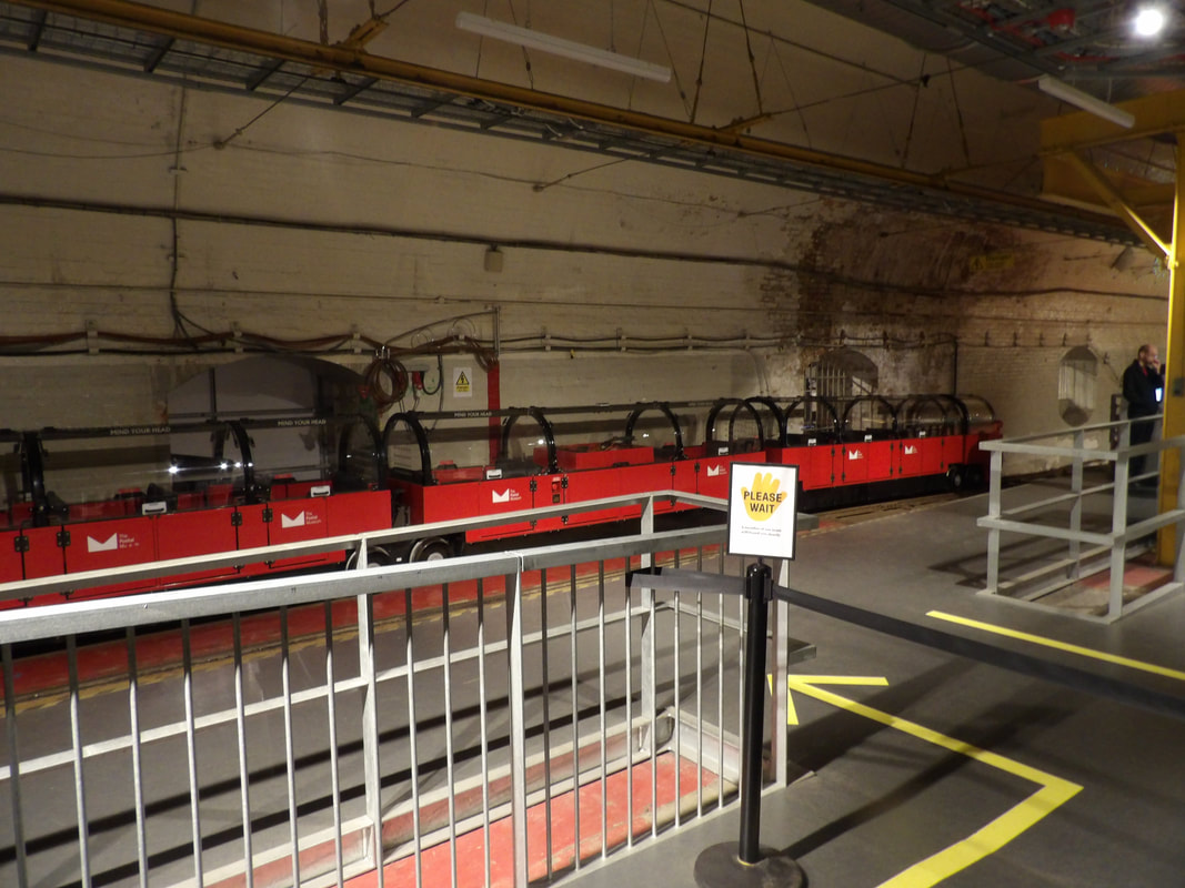 The mail train staged at the station, awaiting its next load of passengers for the tour. At the very beginning, the trains were powered by compressed air supplied by a steam powered system. As the tech advanced, it worked up to battery powered electric locomotives, using large batteries that would put you in the mind of industrial forklifts. As advances continued, the trains became automated, with switchboards controlling the movement of unmanned trains through the tunnels to different stops. The last of these trains ran in 2003, when the whole system was shut down permanently. Concepts were thought up on what to do with the tunnel network but as of right now, the tunnels lay dormant, all except this short run of tunnels, serving as an amusement park ride. 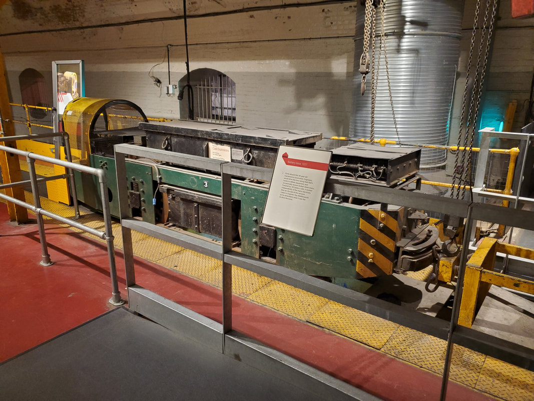 A mail rail locomotive, with a large battery pack in the middle of the carriage. 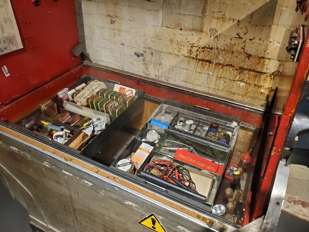 A retired mail cart that was set up as a maintenance cart by one of the mechanics who worked to keep the mail rail system running. After getting our ride on the old mail rail system we made our way to the regular museum where they have displays with all manner of factoids on the forming of the mail system 500 years ago, to the advancements in the system as far as technology and standard operating procedures. Stories of the mail system and the role it played through the ages, especially during the 20th century in WW1 and 2 are all interesting to take in. One gets to see how automotive tech allowed mail to move faster, along with aircraft and ships. Stories of how overseas mail ships had to deal with pirates and would fight to the death if necessary, and in the worst case, ensure mail does not fall into enemy hands. These crews tended to successfully fight off many pirate attacks, even taking prizes in return. 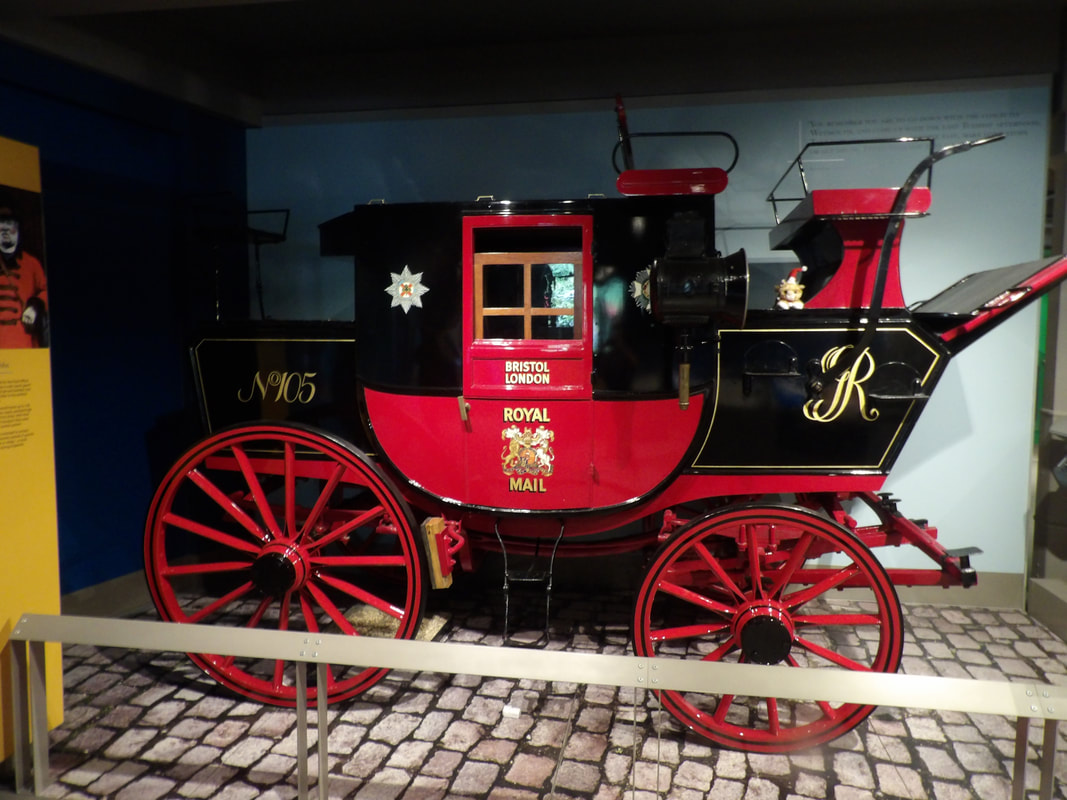 Horse drawn carriage used for delivering mail. An advancement from the UK version of the Pony Express. 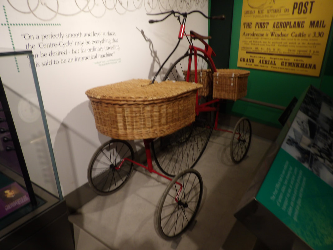 Even on the localized level, different means of conveyance were utilized for carriers to get mail to individual addresses, like this 5 wheel what would you call this? Pentacycle? 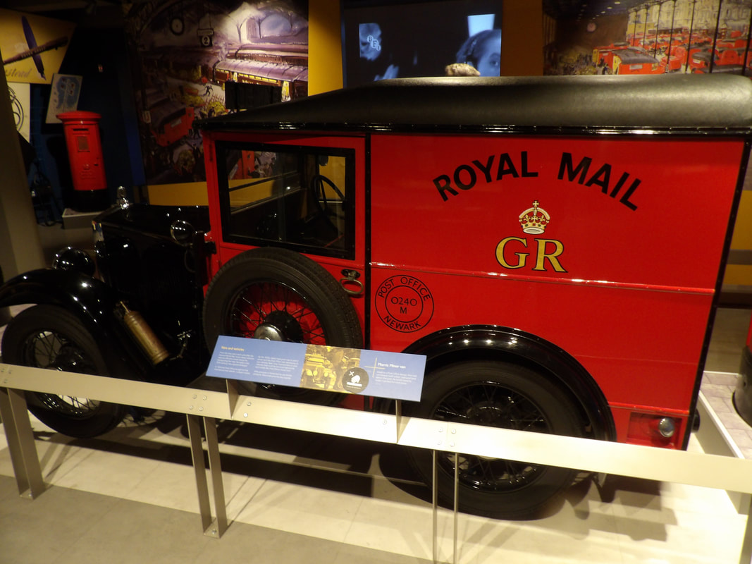 As automobiles came to the scene, the mail service instantly took hold of the new tech to move mail faster. 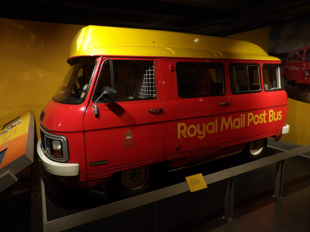 This 80s Dodge post bus mark the postal services use of regular motor vehicles as standard equipment in moving the mail across the country. Of course with the advancements in electronics, mail processing equipment came to the scene as well. Concepts with decoding machines, even far back before electronics really took hold in the civilian world, made the processing of mail better. The story behind the development of the post code system and the campaign to adopt the new post code system nationwide is told. Mail processing machines, just like in the US, came to the scene, and continue to advance, to allow for rapid processing of large quantities of mail. 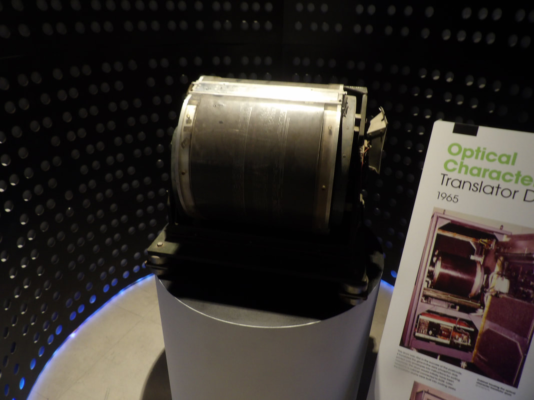 Optical character translator, c 1965, used markings that were translated into a sorting code, kind of like an ASCII code does on a keyboard. with binary coding. 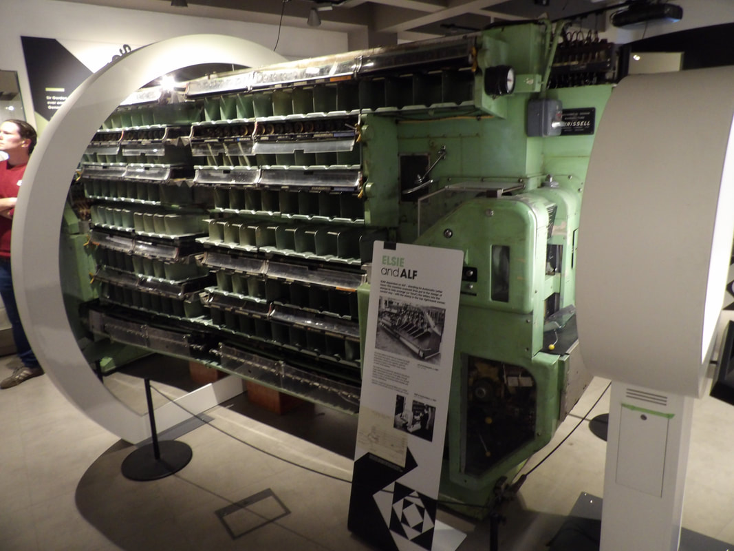 A more primitive letter sorting machine, a precursor to the digitized letter sorting machines that can process thousands of mail pieces an hour by reading addresses via computerized cameras. After the Postal Museum, we hit the subways again and made our way to the London Zoo. This took a bit of a hike to get to, on the trains and on foot. Once there we made our way around, checking out the animal exhibits, many of which were unfortunately vacant. Those that we did get to see were as usual, entertaining. It's always cool to see different animals up close, especially exotic animals that one may not be exposed to in their locale. 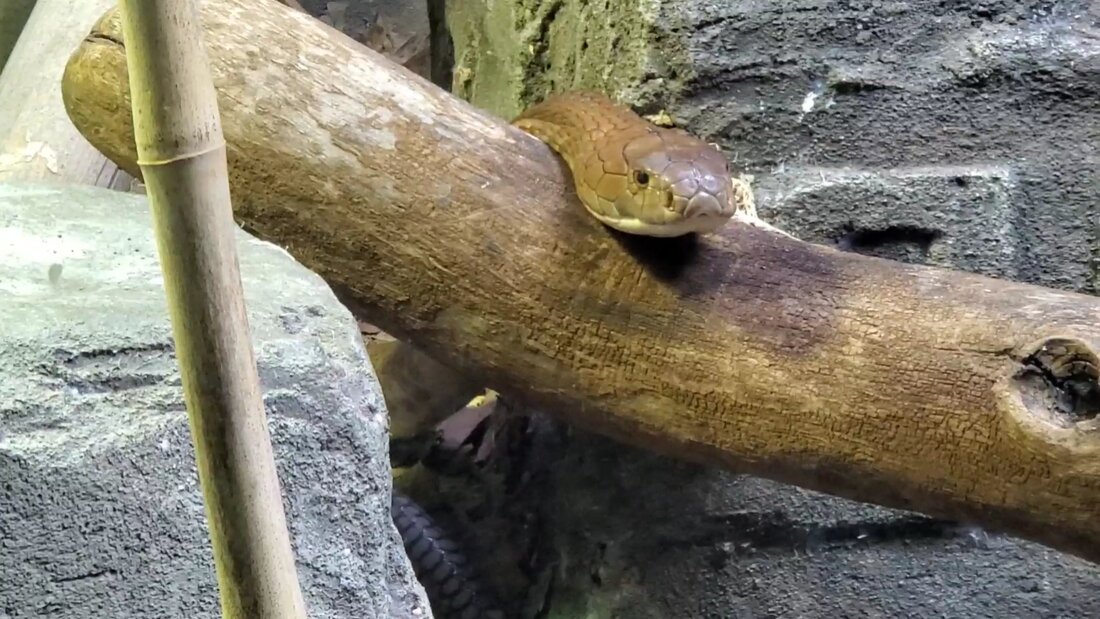 This constrictor appears to be photogenic. 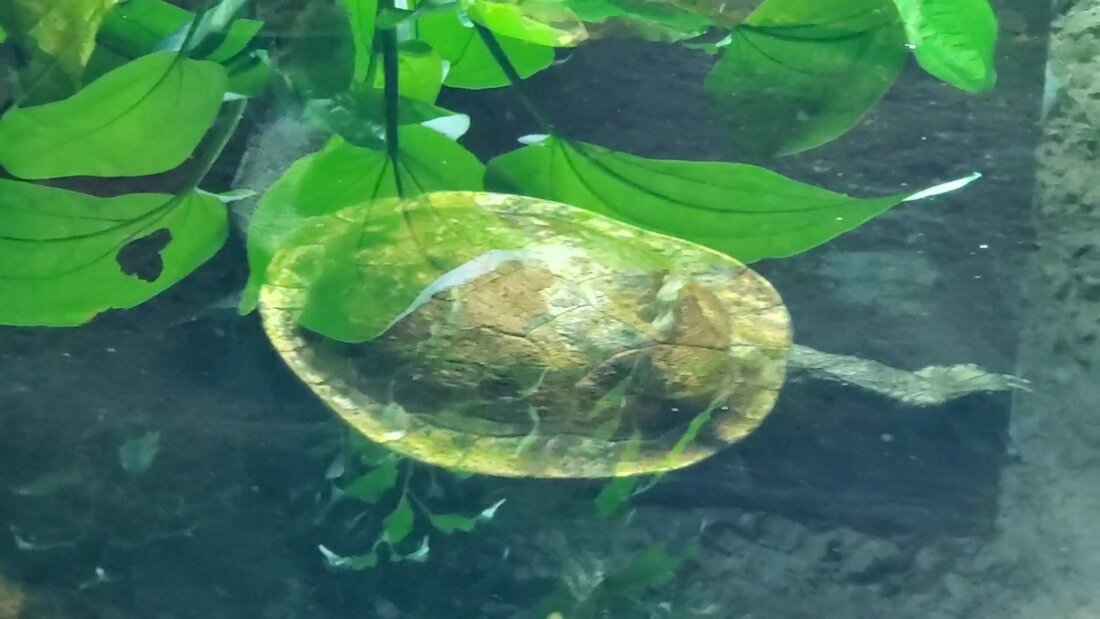 African side neck turtle 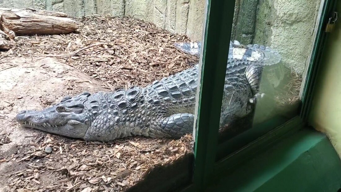 Lazy croc 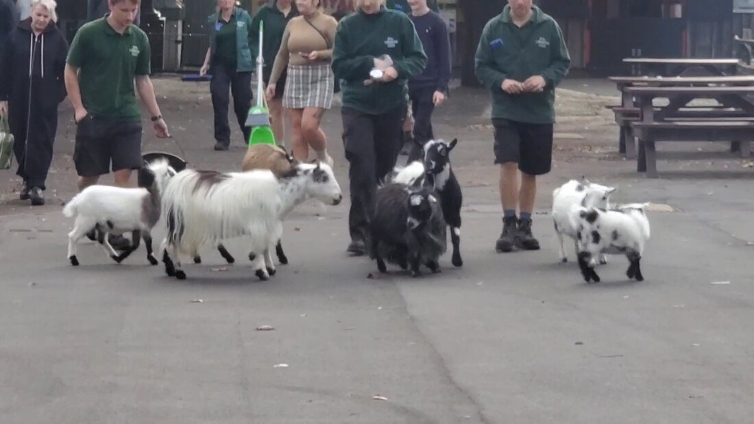 Herding goats 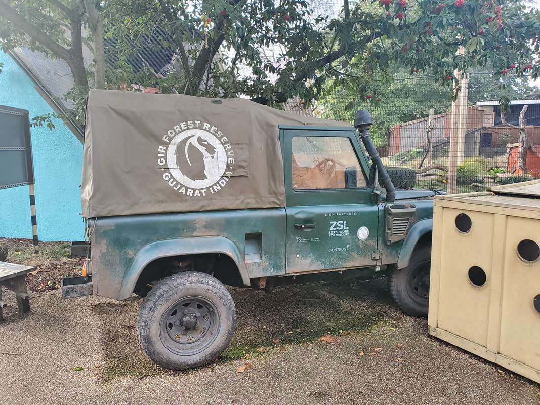 An old Landcruiser truck set up as part of a zoo display. Gotta love old automotive displays. 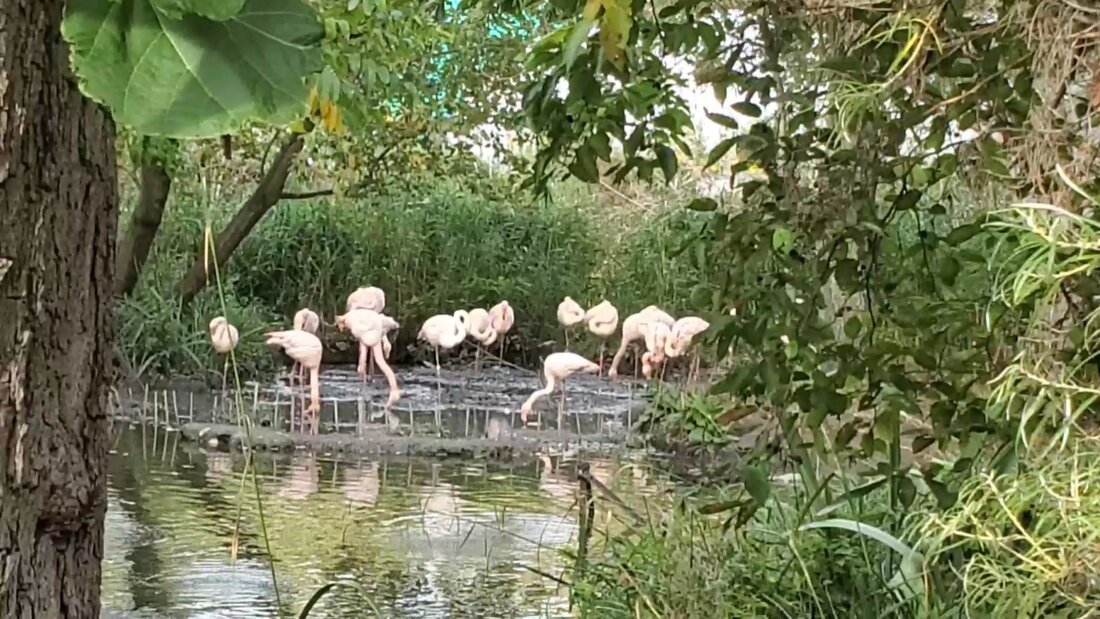 Flamingoes 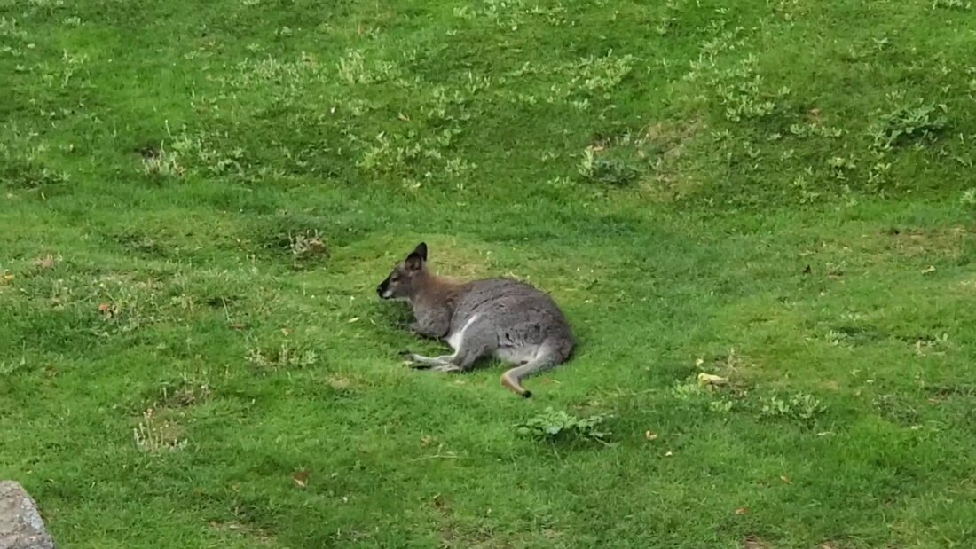 Wallaby chilling on a cool day.  Hippo  African wild dog The zoo was set up to accommodate those animals whose natural habitats may be a lot warmer than the local climate in London. As it was rather cold, those animals that would normally call the hot savannahs of Africa home had indoor facilities available for them to take respite in. This zoo is run by a nature society that dates back to the 1800's with such names as Charles Darwin taking part in its creation and growth. 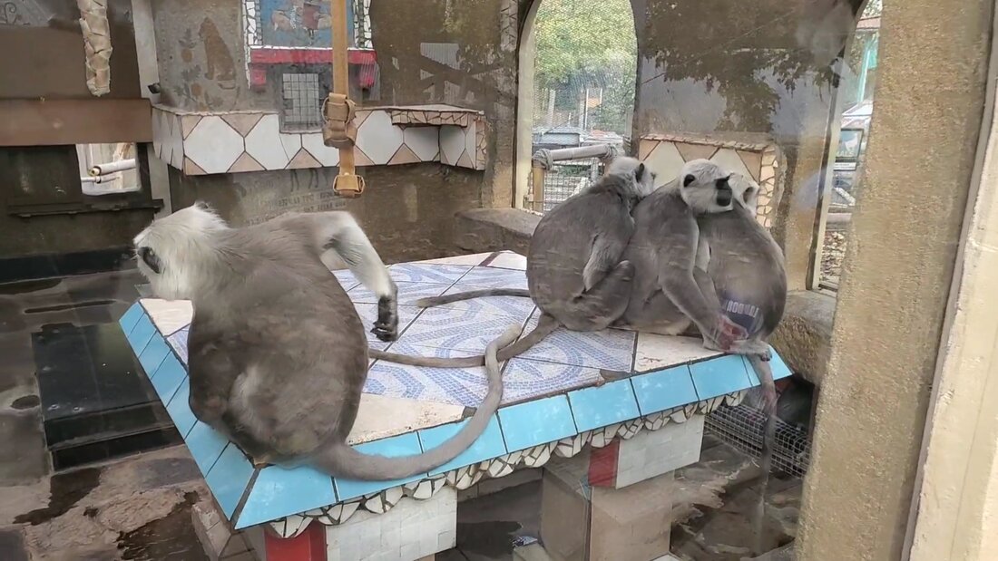 These monkeys are hanging out inside where its warm. 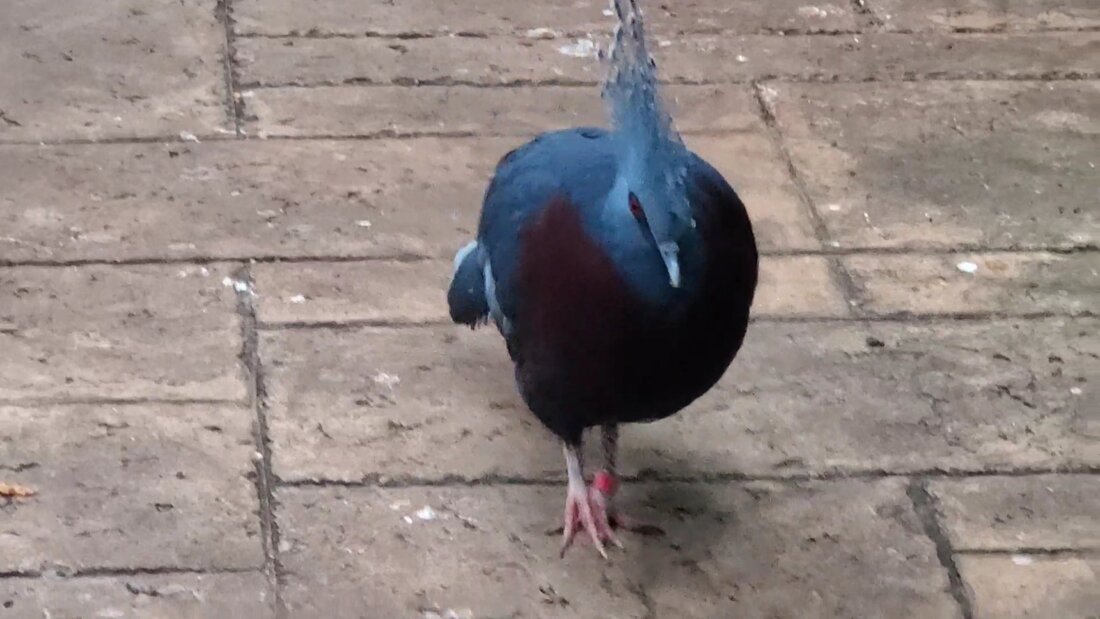 This bird is living it up inside an aviary, with free reign of the place. 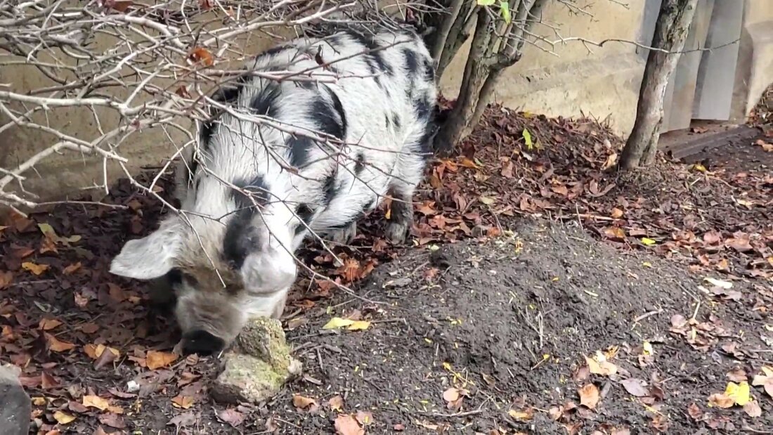 Here piggy piggy 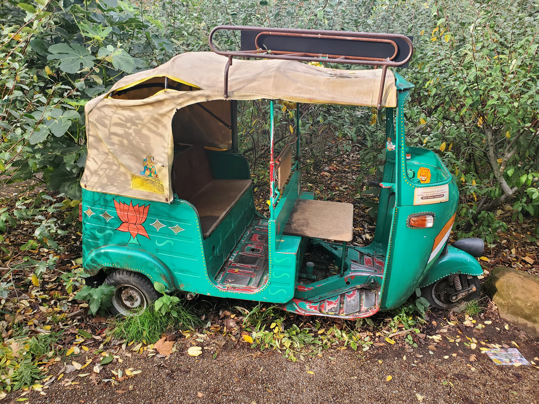 A three wheeled transport as would've been seen in different places across Asia or Africa, also on display. 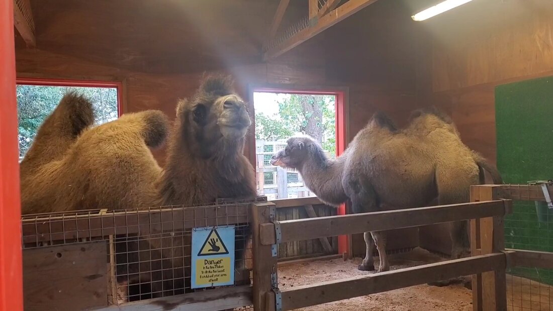 These camels are hanging out inside where its warm. 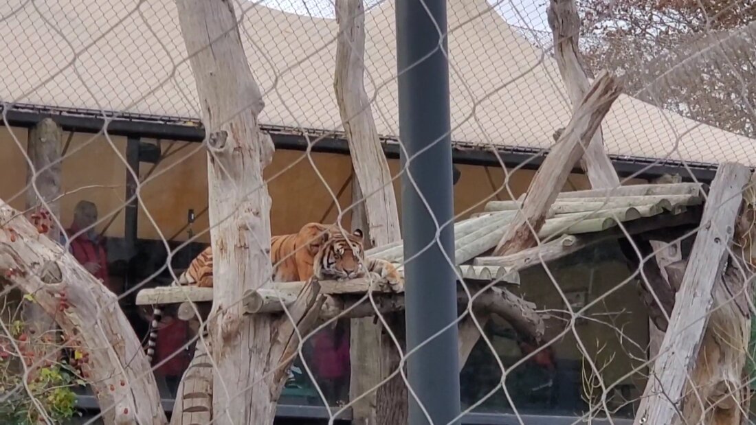 This tiger isn't too concerned with the cool temps, as can be seen. 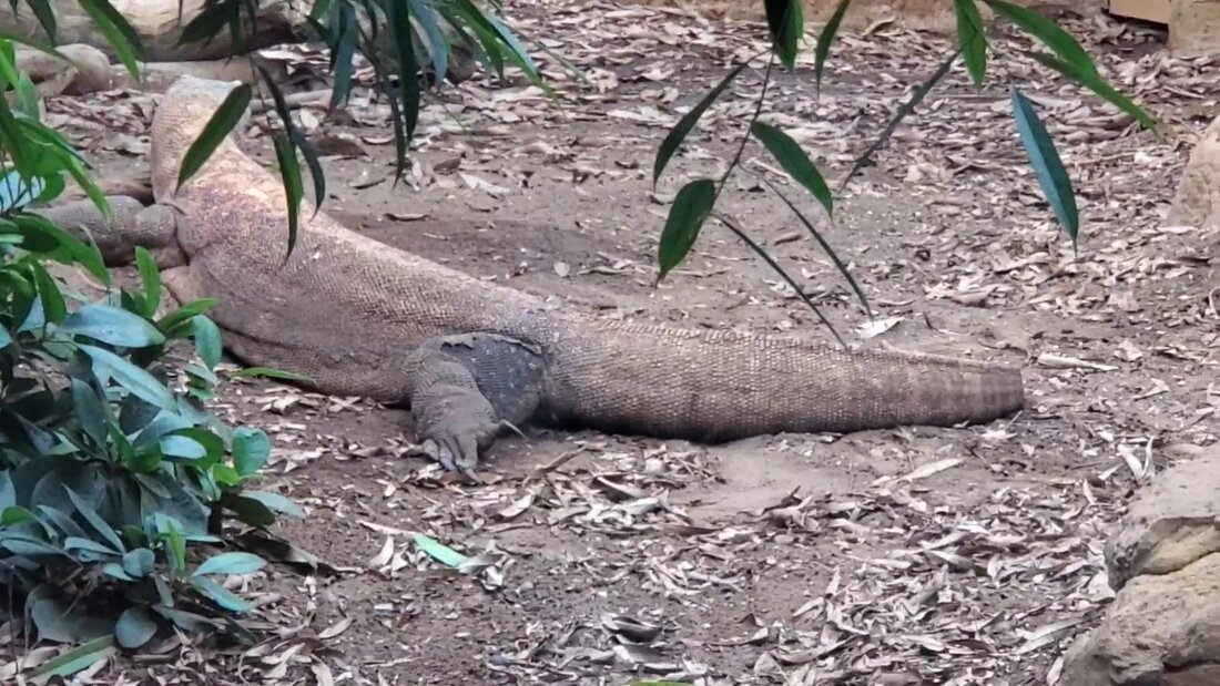 Komodo dragon  Emu 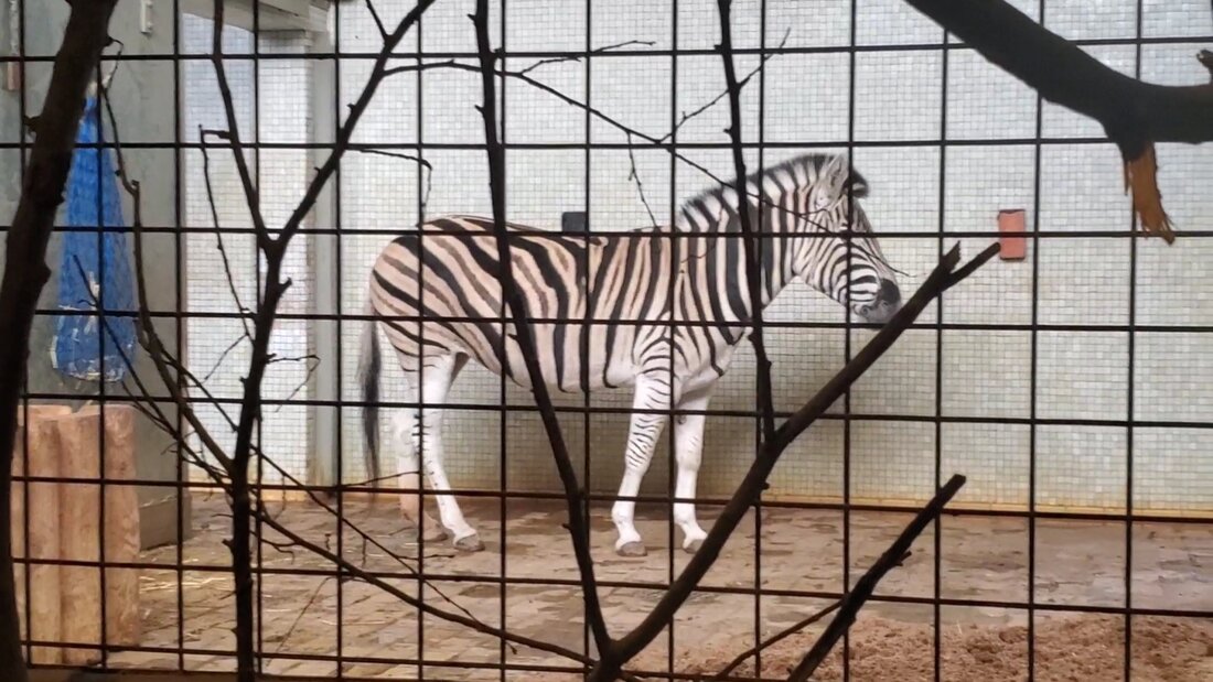 This zebra is indoors keeping warm 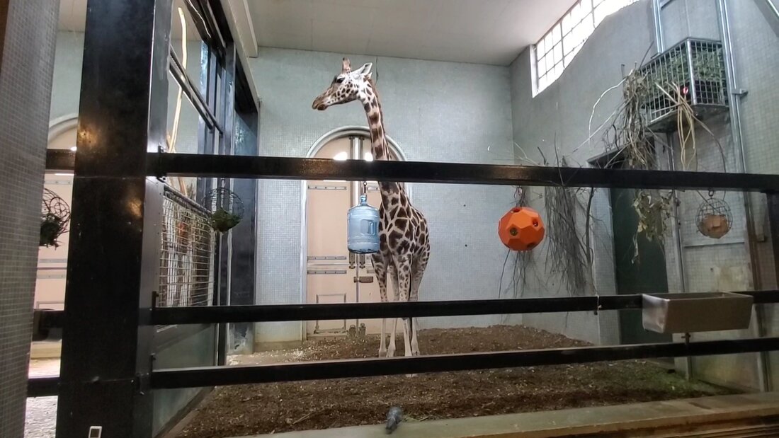 Same goes for this giraffe  These otters are posing  These meerkats are almost domesticated 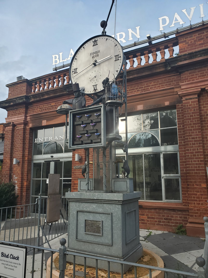 A cool mechanical creation built around a clock, little metal birds come in and out and move around, a literal clockwork piece of art. 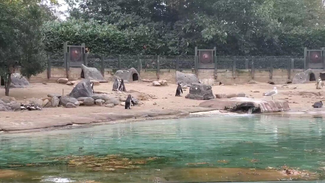 Penguin beach 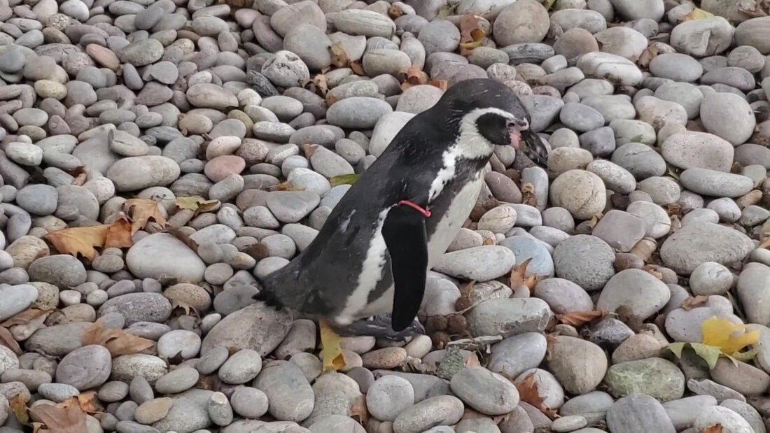 Little penguin just waddling around, enjoying the weather 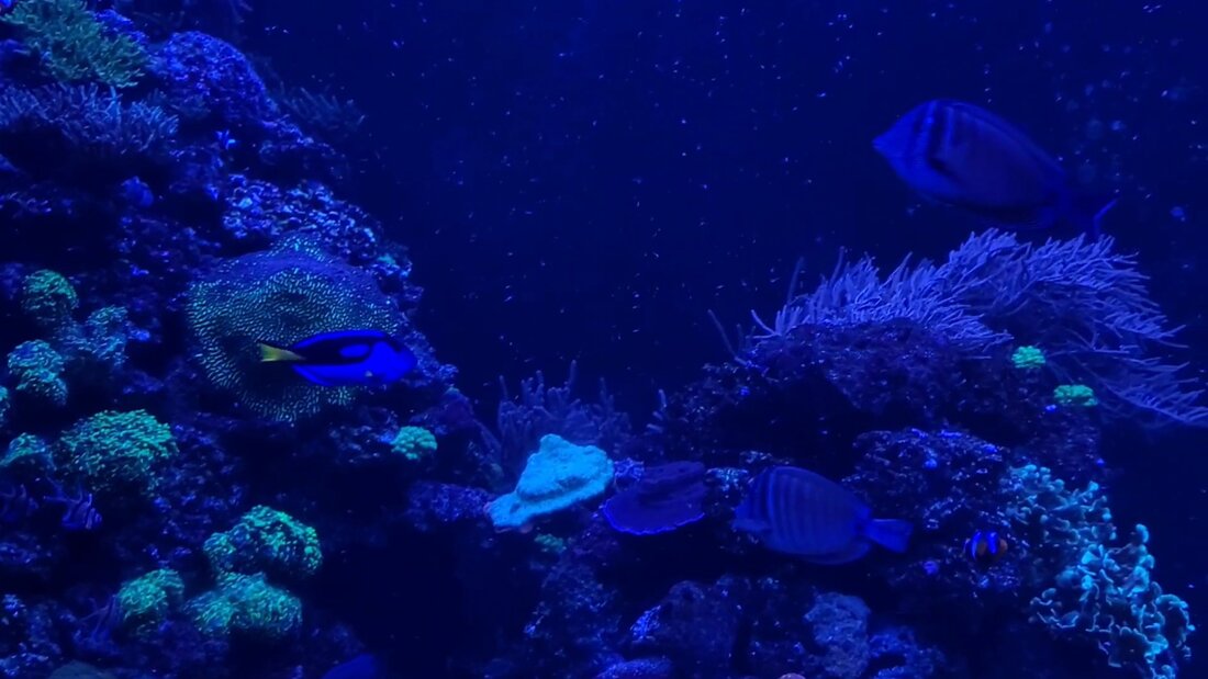 Tropical fish in aquarium We were able to make it through the zoo and even the gift shop with just a few minutes to spare before closing time. Since it was getting late, rather than walk back the 3/4 mile distance to the subway station, we took a Bolt, UK's other Uber, the short distance back to that point so we could get on the train and back to the hotel that much sooner. The next place we will be hitting up on our last part of the London tour is the National Army Museum, which showcases the beginnings, growth and role the British Army plays in the world, then and now.
0 Comments
On our second day in London we had started off with the intention of visiting one of the palaces that are in the city, having used to belong to past royalty. After traveling close to the destination and walking through the park where the facility was located, we found that the place was closed that day. With that plan falling through, we made our way to the area where the London Bridge was located. 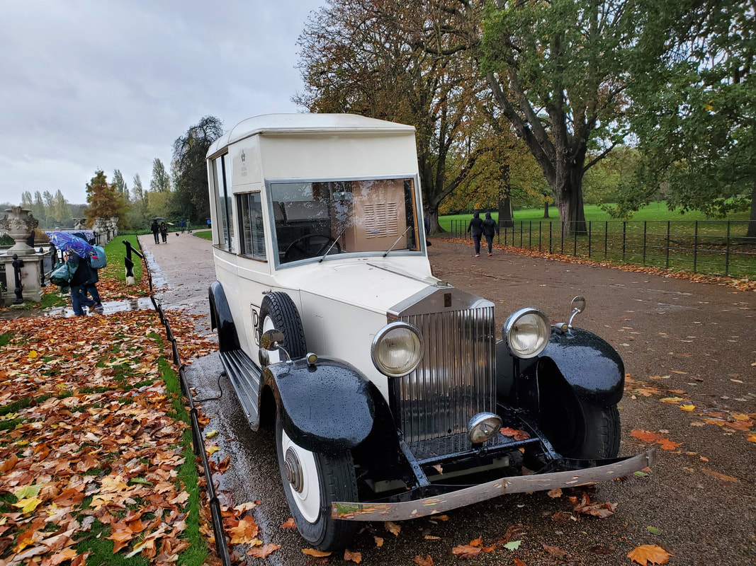 An old Rolls Royce car made up into an ice cream truck at Kensington Park. 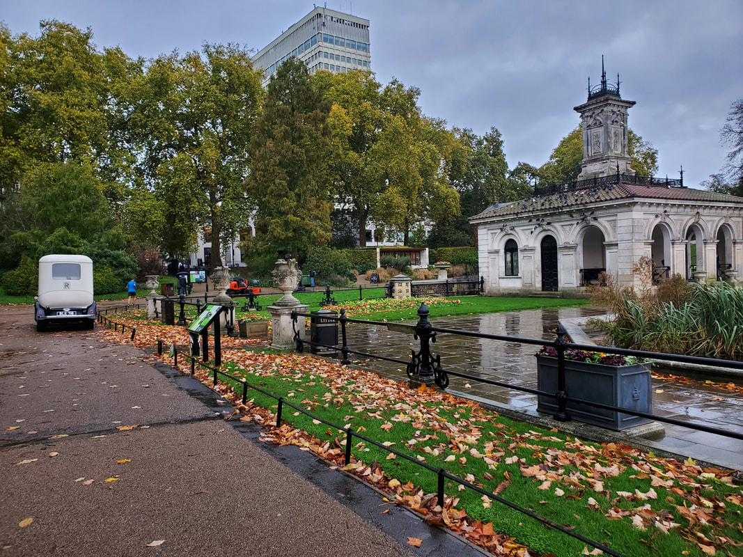 A shot of a pavilion at one end of the park. 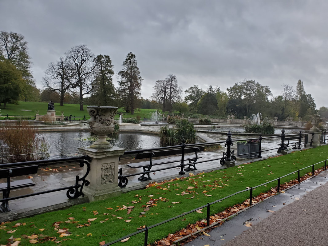 The pavilion makes up part of what's called the Italian Garden. 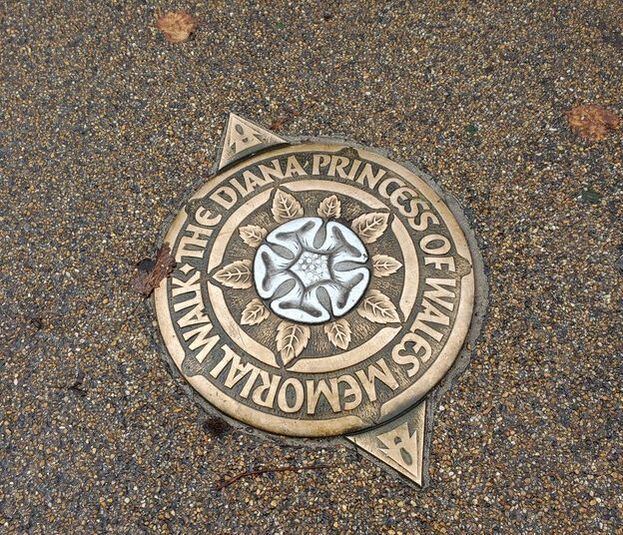 This memorial plaque sits in the walkway as a tribute to Princess Diana. 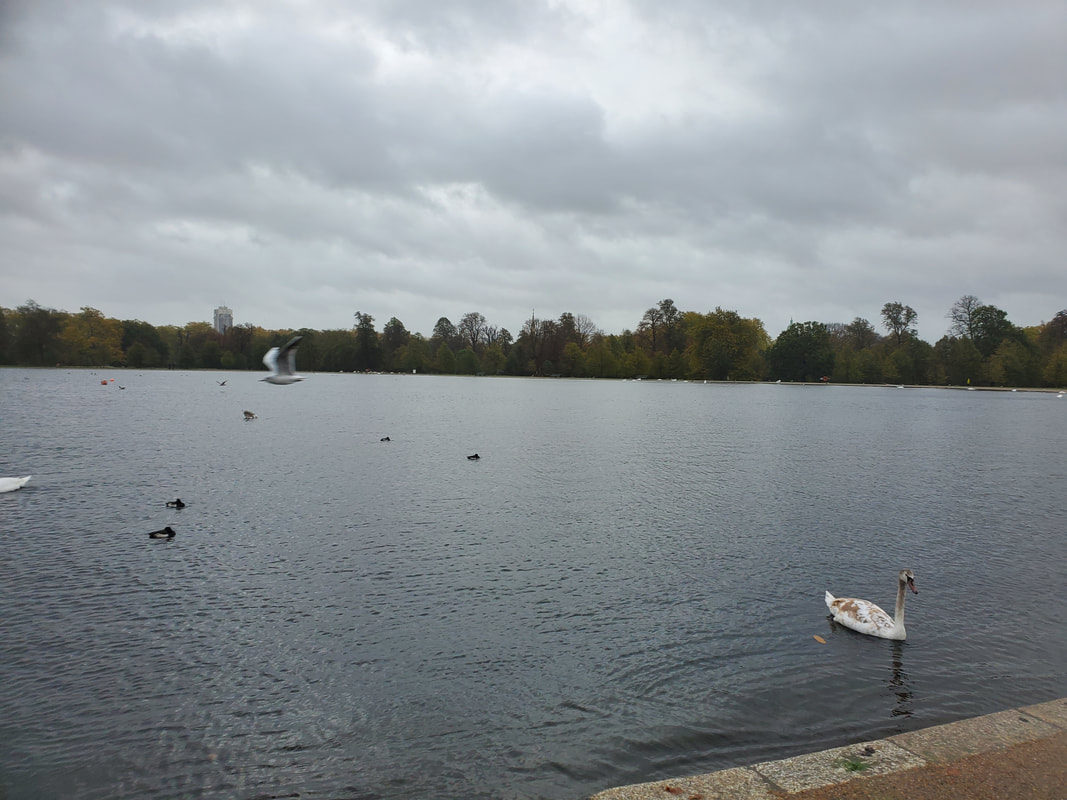 Large lake in Kensington Park, near the Kensington Palace. 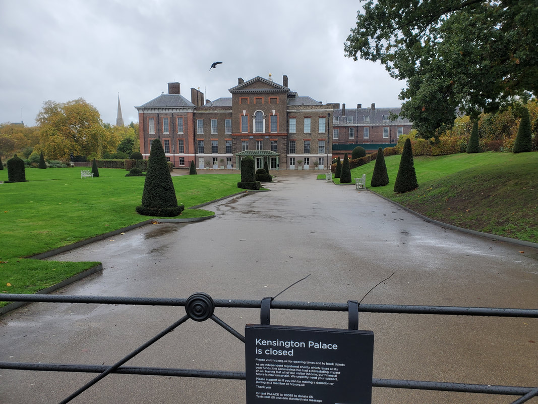 Kensigton Palace, which unfortunately was closed. Getting into the area we stumbled across one of the tourist attractions I wanted to check out but totally forgot about. The HMS Belfast, a WW2 era battlecruiser is anchored on the Thames and serves as a museum, The ship is kept up to original conditions, looking as it would've when it sailed, with the addition of a cafe and bathrooms, along with facilities for overnight tours and groups. We spent a good amount of time touring the ship, from the bridge all the way down to the boiler rooms and fore to aft. Once we had our fill of the HMS Belfast, we made our way to the London Bridge. 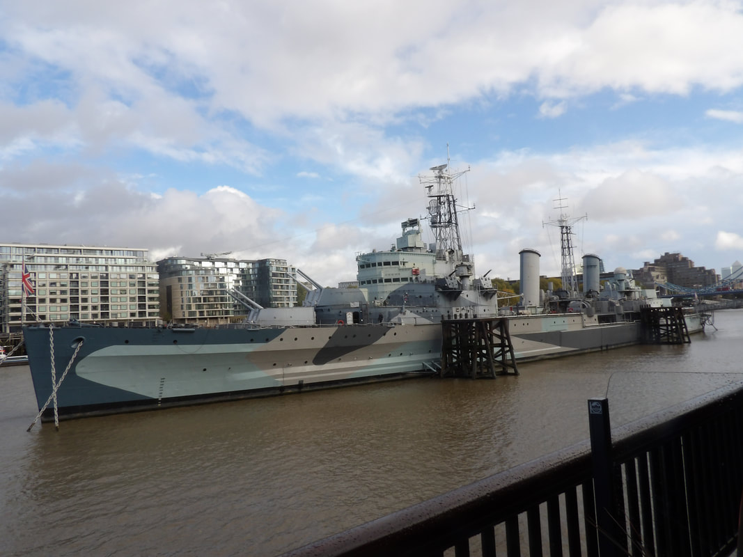 The HMS Belfast battlecruiser, anchored on the Thames. 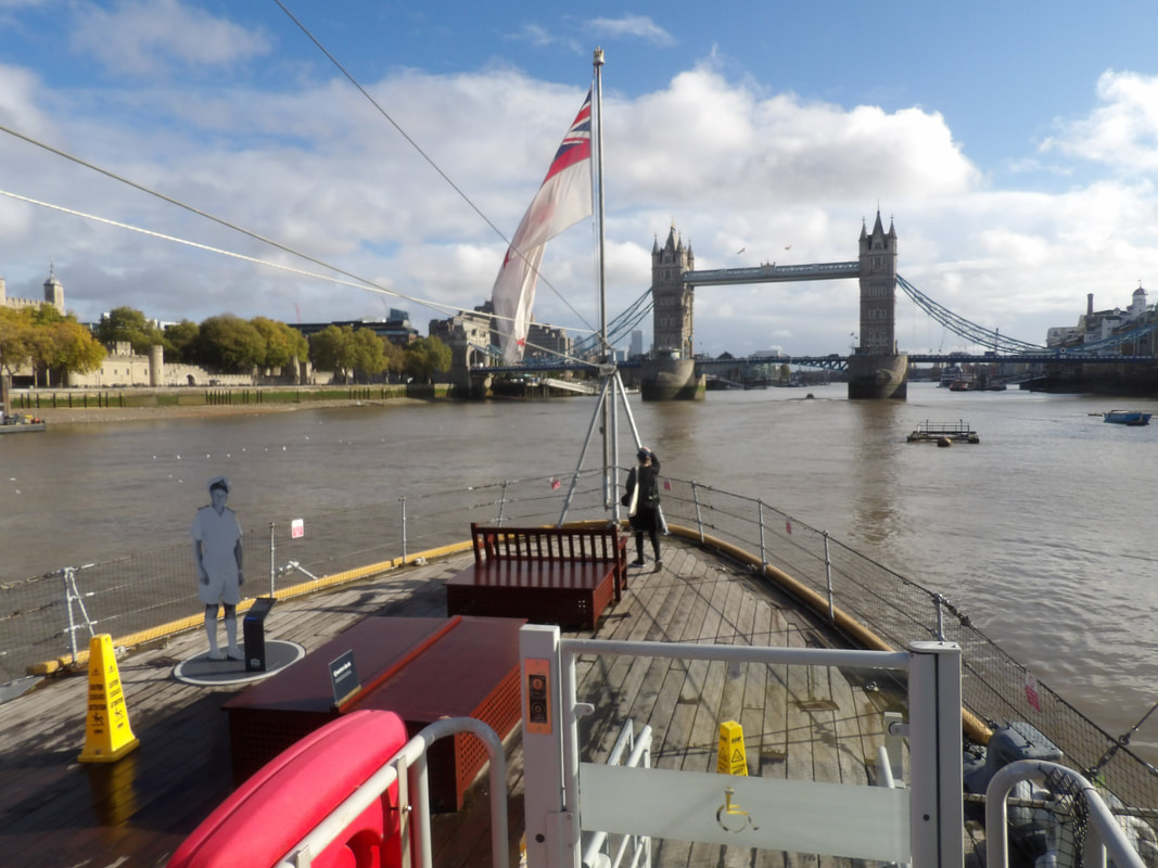 The stern of the Belfast, looking back at the London Bridge. 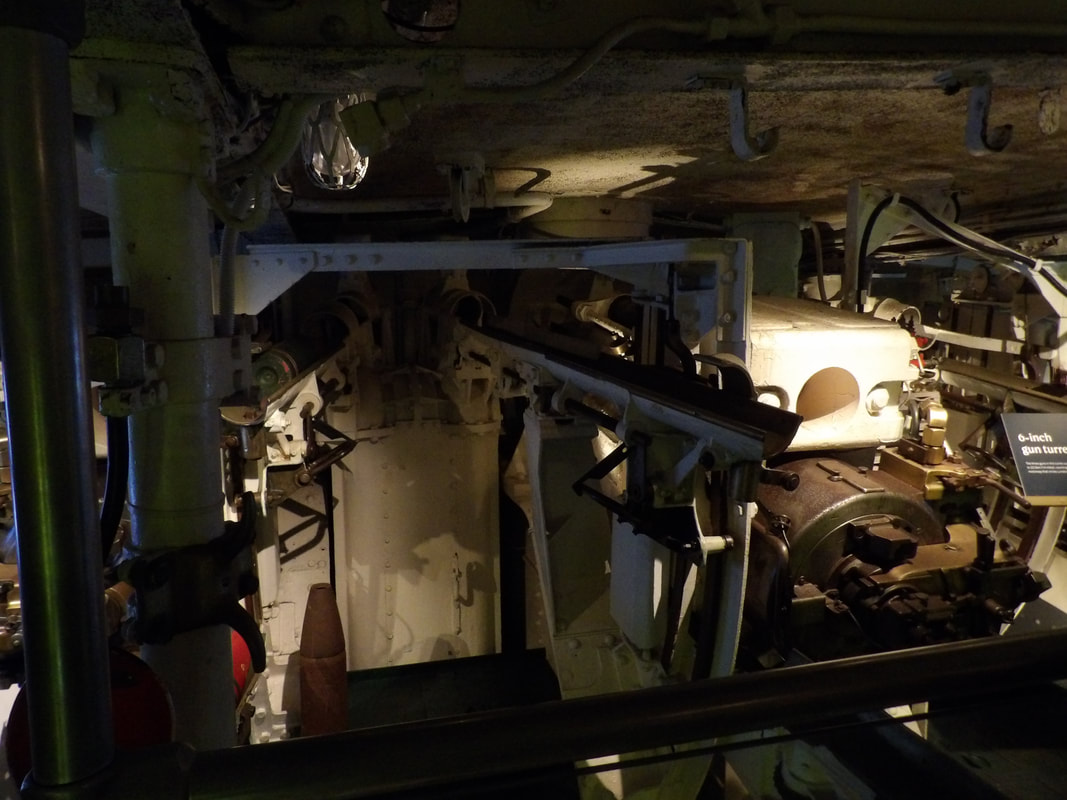 One of the four three 6" gun turrets interiors. 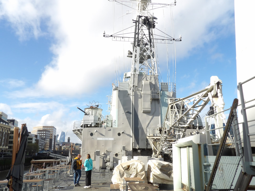 Looking at the superstructure of the ship. 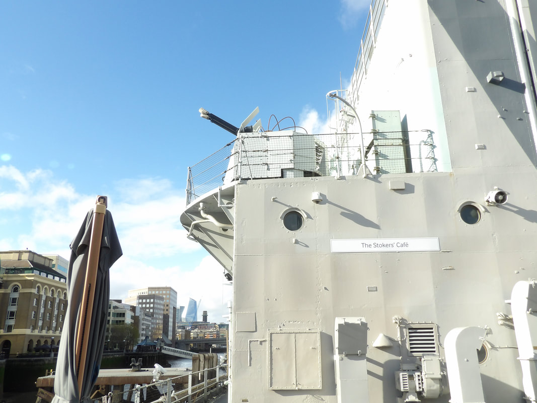 40mm Bofors AA gun on upper deck. 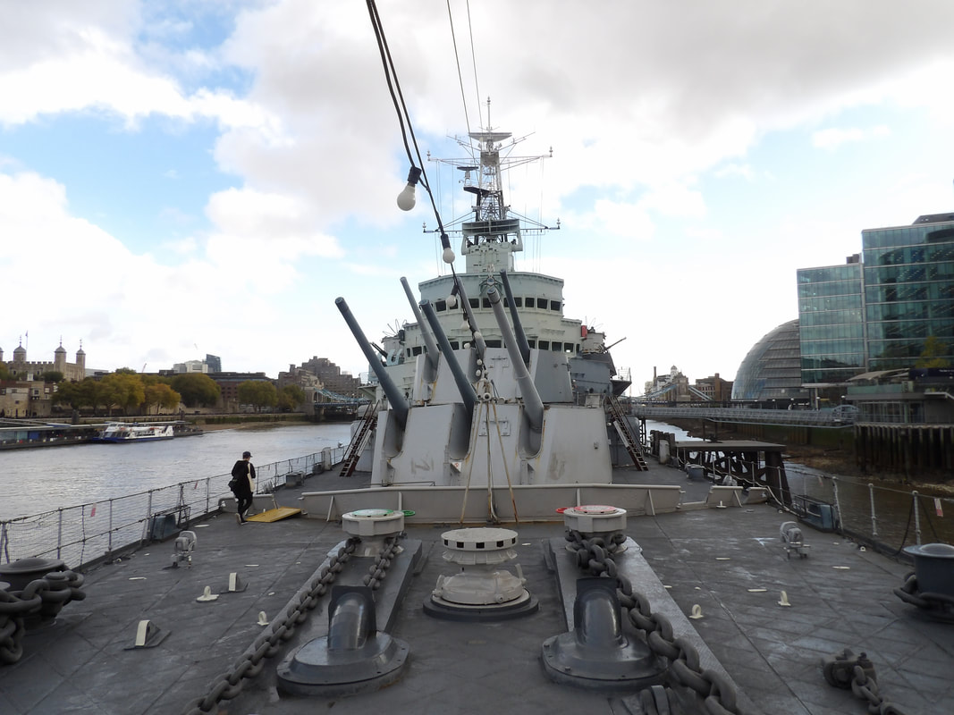 At the bow of the ship looking back at the two forward gun turrets and superstructure. 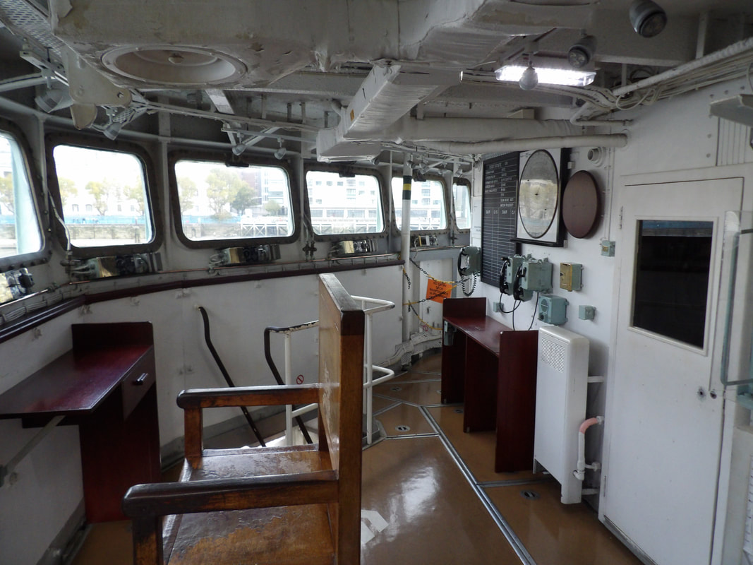 The bridge of the ship. 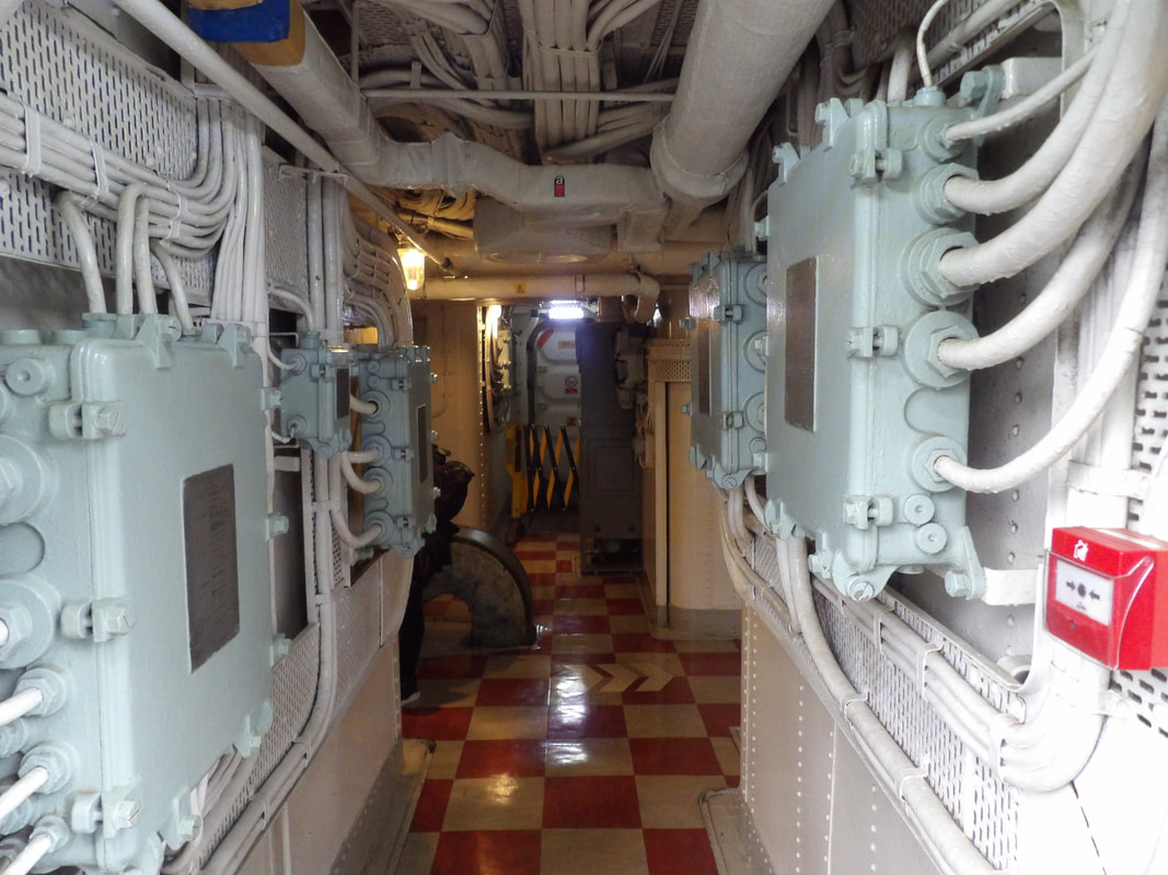 Walking down one of the corridors below decks. 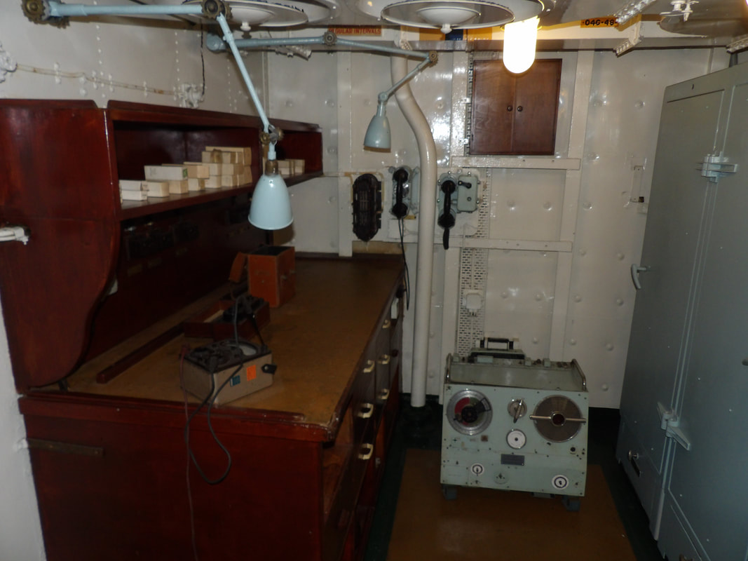 Radio repair room, showing parts on shelf along with radio on display. 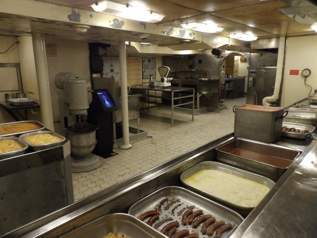 Galley of the ship, showing how everything is laid out. 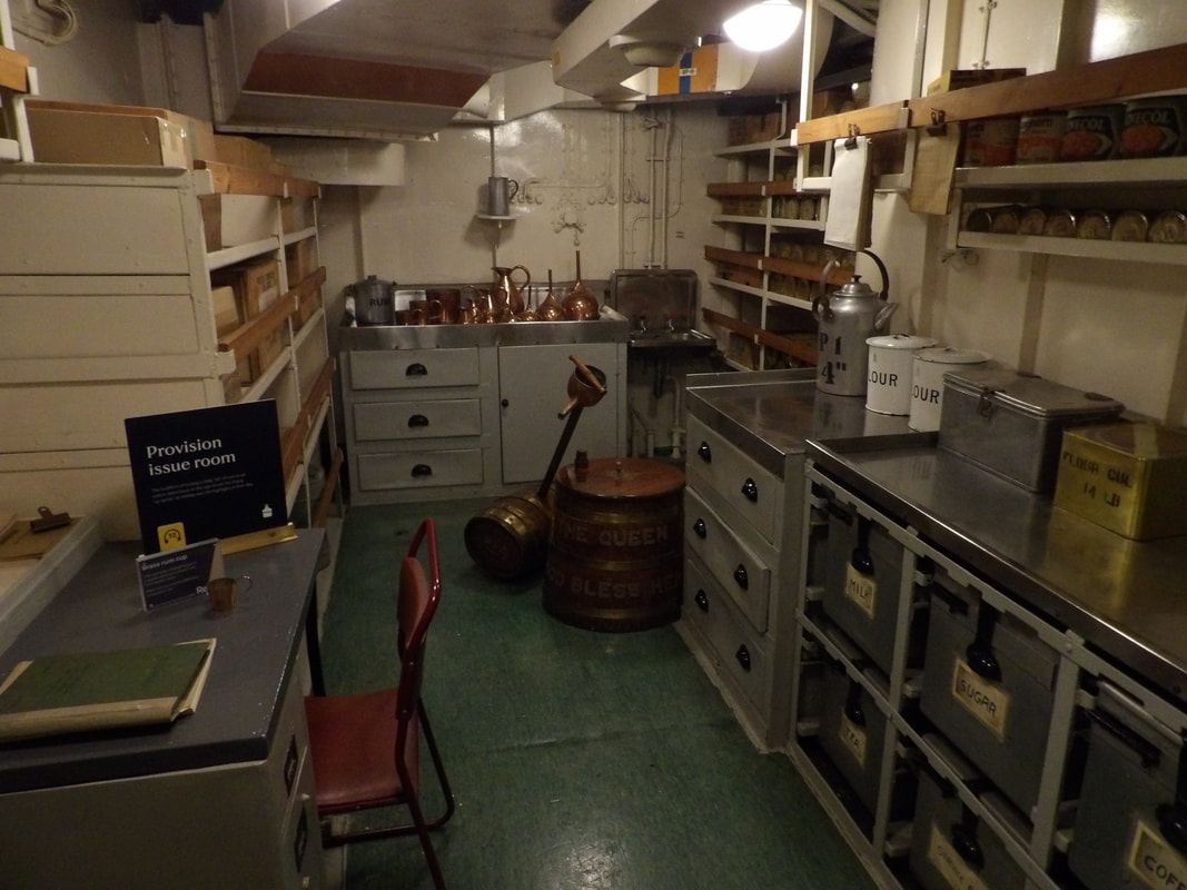 Provision issue room, where supplies are issued for use in the kitchen and elsewhere. 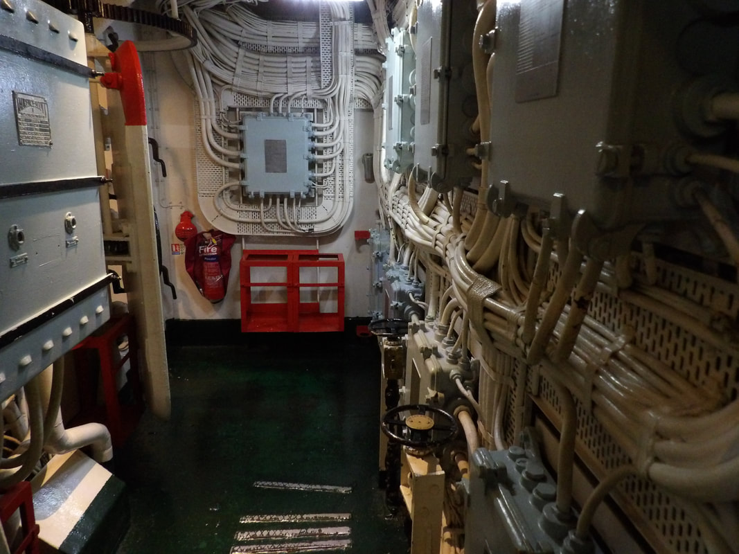 Another equipment room showing the hardware in place. 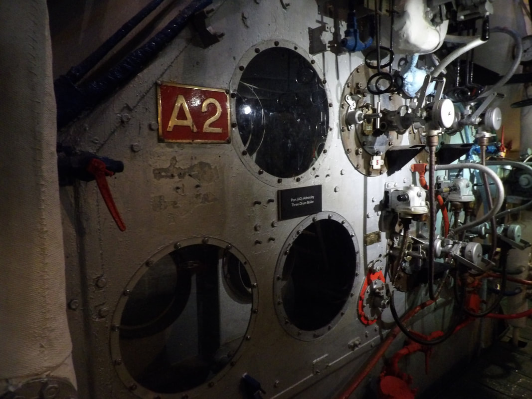 One of the boilers below decks in the boiler room. 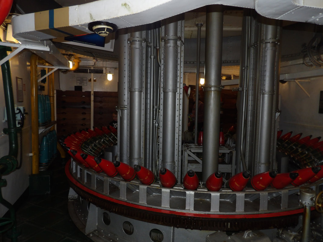 Below one of the 6" triple gun turrets, showing the magazine mechanism, bringing shells into position to be staged and loaded into the lifts up to the actual guns. At the London Bridge we checked in and walked up the huge number of stairs to get to the top of the south tower where we read a bunch of factoids on the construction of the bridge before making our way into the west walkway, reading more information on the bridge, along with getting some nice views over London proper and the river from way up high. There was even a section of the floor made up of glass where you can walk over and look straight down to the roadway and the river, far down below. Those with weak nerves may not care for this but it is very interesting to check out. We made our way across over to the north tower, then across the east walkway and back to the north tower and down the stairs. Once back on ground level we went into the engine room area where the old coal fired steam boilers and piston engines remain preserved. These old powerplants supplied the steam power to raise and lower the drawbridge up to 1971. Now the system is electric and hydraulic powered. It's interesting how this bridge used this primitive power plant all the way up to the late 20th century. 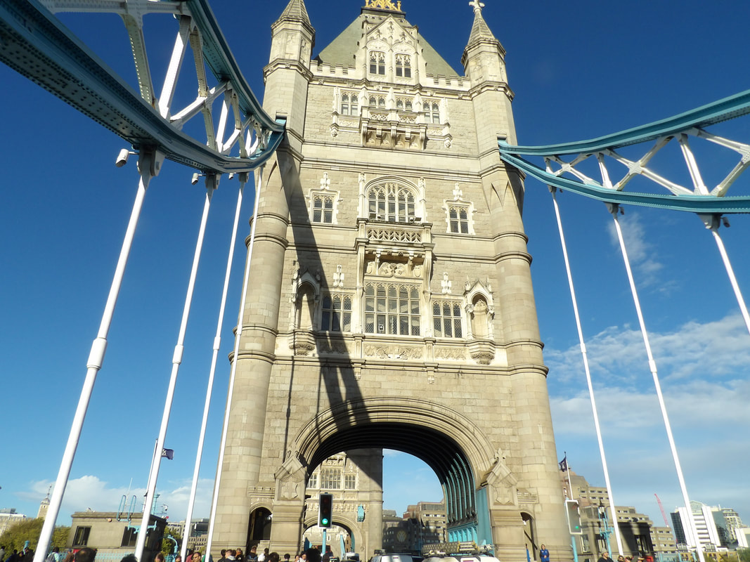 Shot of one of the towers of the London Bridge as we walked the roadway. 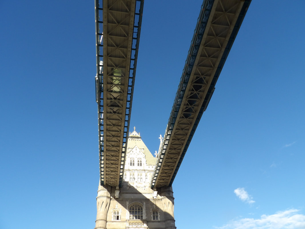 The twin upper walkways between the two towers on the bridge. 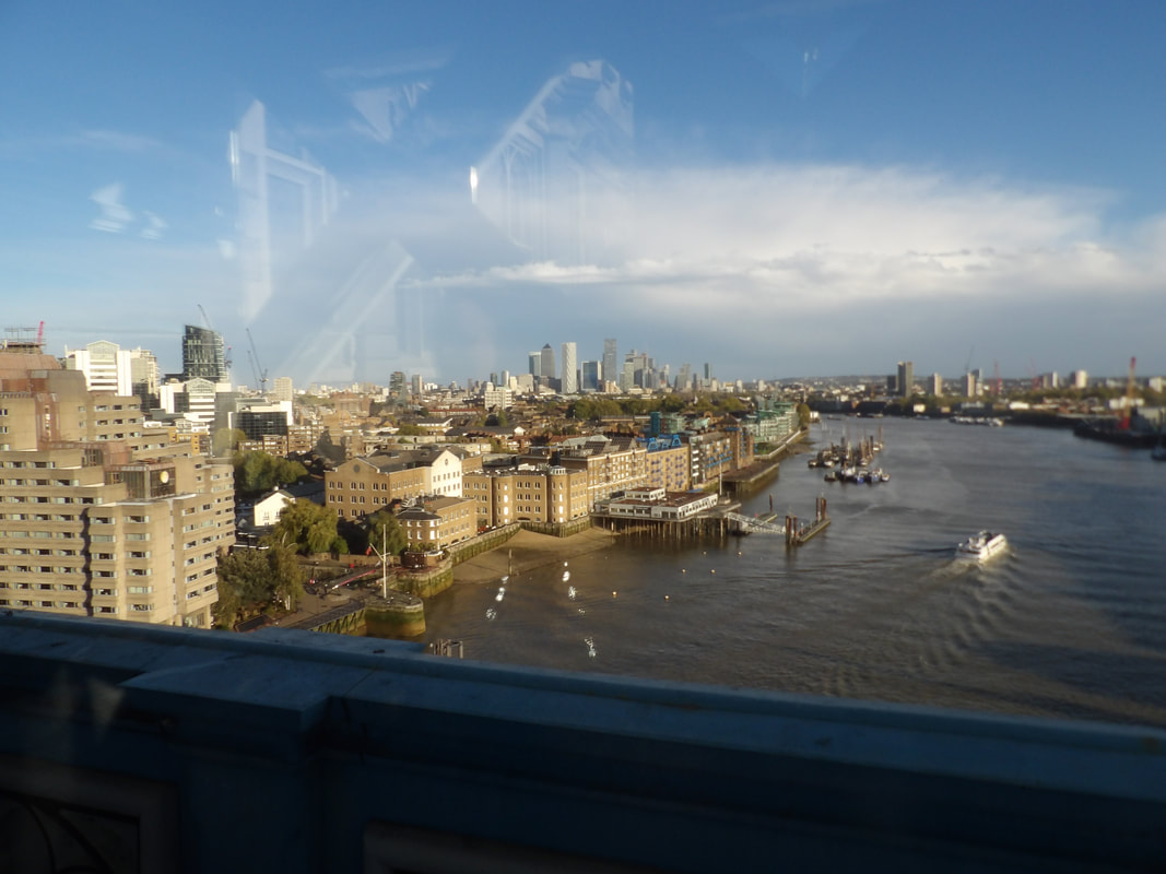 A look from the west walkway overlooking the river and the city skyline. 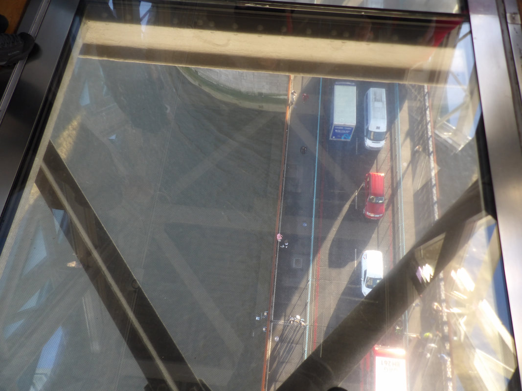 One of the glass floors on the walkways, allowing you to look straight down to the roadway and river below. 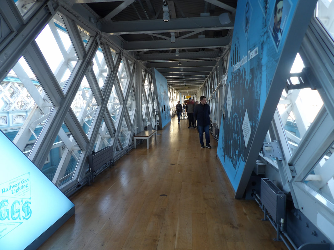 Walking the east walkway. 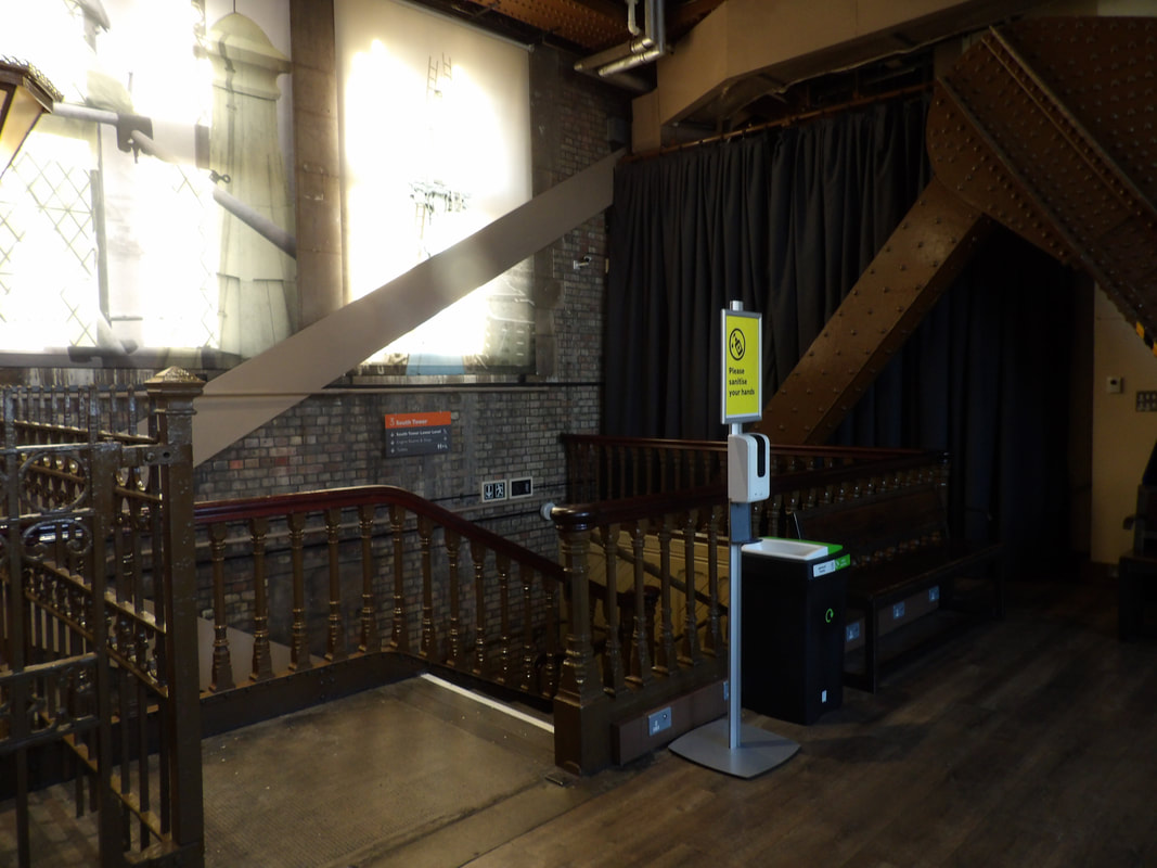 Inside one of the towers, showing the steel girders that make up the framework of the structures. 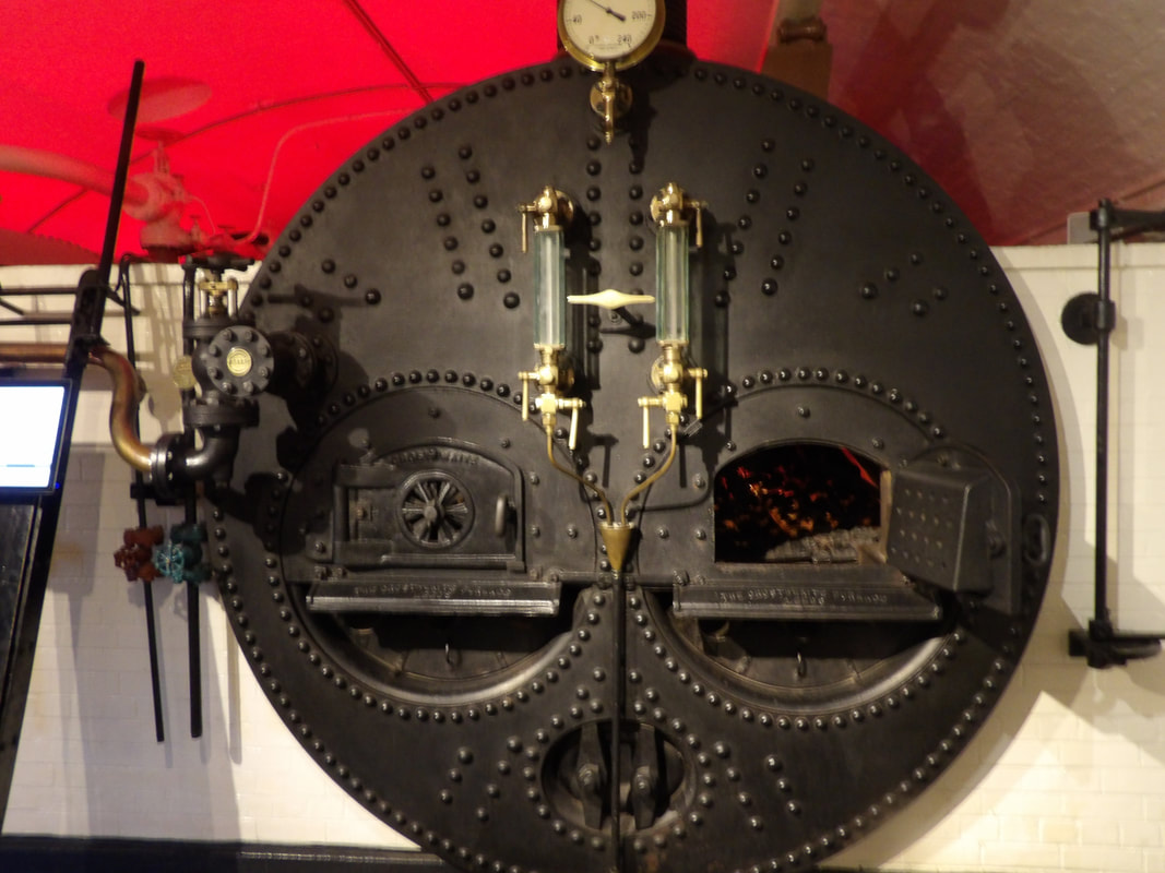 One of the boilers that supplied steam power to operate the bridge. 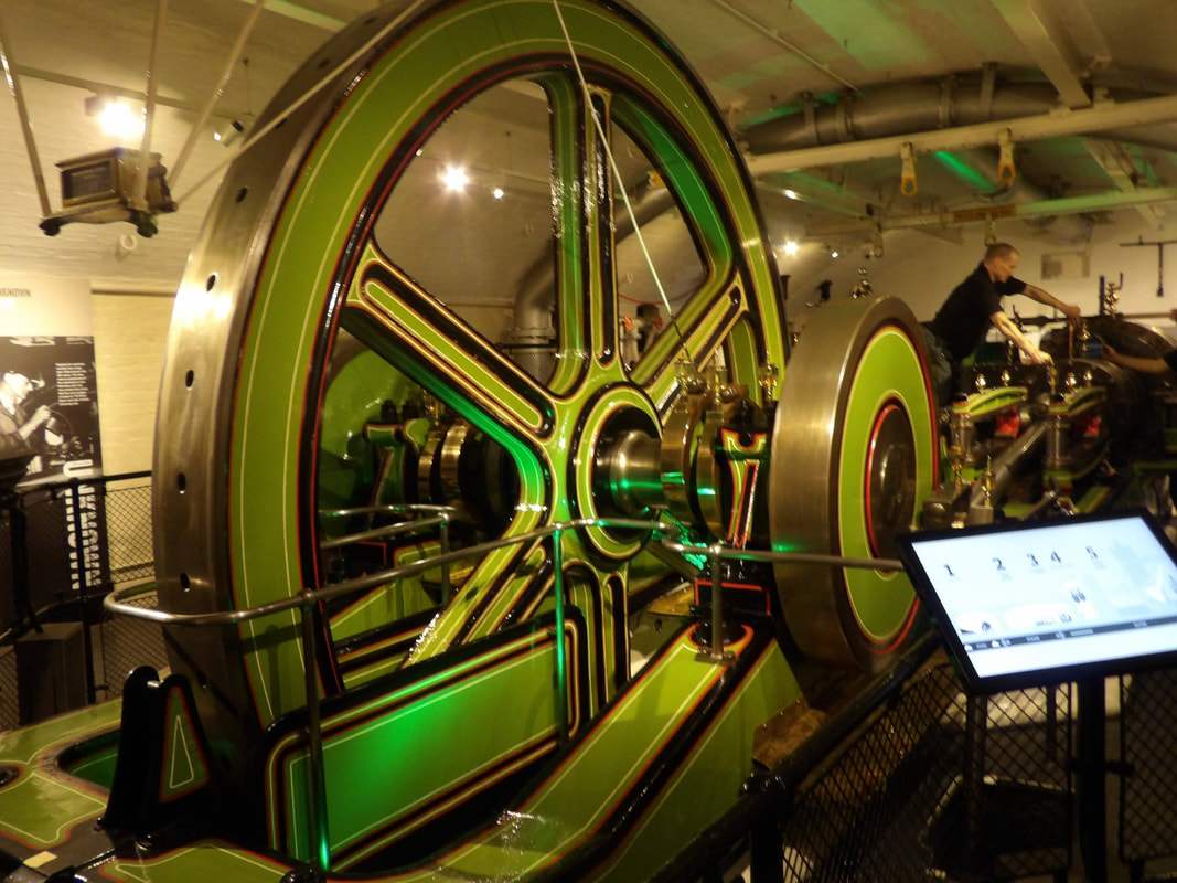 The flywheel of one of the steam engines in the engine room. 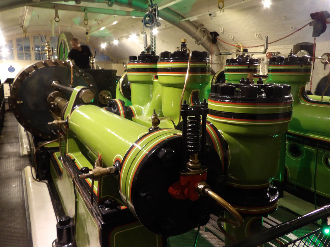 The piston/cylinder end of the steam engine assembly. Lastly, we took a little train ride over to another part of town where there was a Chinese buffet restaurant. The area we came up into from the subway was like a little version of Times Square with a lively lit up part of town with many shops and restaurants and other venues for people to spend money in. We navigated through this area over to the restaurant to eat up then hit the train back to the hotel to chill for the night. 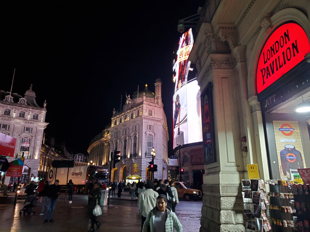 The area of the city at the station, Picadilly Circus, looks like a mini Times Square. 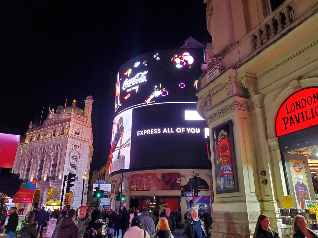 A large digital display advertising different companies. 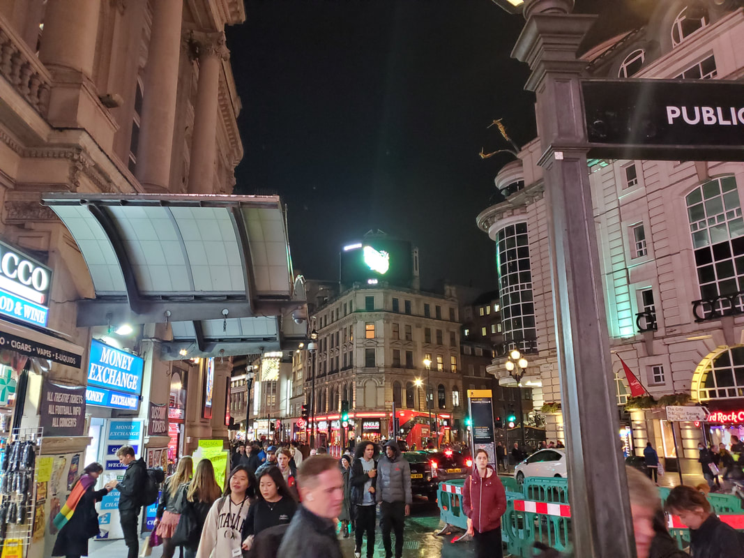 And yet another angle, note the large number of people on the streets. Filled up like little ticks, we chilled for the night, able to do a few things before finally crashing once again around 930-10pm, ready to pick things back up again and hit a couple more tourist spots in London, namely the Postal Rail Museum and London Zoo. More to come... After waiting for a good while, we get to go on another trip again, but this time this will be a multi part trip due to the fact that the first leg of the journey is to travel to the UK, specifically London, UK. We plan on staying there around 5 days in order to just be able to take in the sights there before making our way to Southampton where we will stay for a day to see a couple things there before getting on a new cruise ship Carnival is bringing out, the Celebration. This large ship will shadow most of the other ships in their fleet and have many more amenities and room to roam. Once on the ship we will travel to four ports around Spain for one week, then on the 2nd week travel across the Atlantic to Miami where they will be keeping the ship. With that, this trip will last a total of three weeks. The first order of business is getting there, which of course involves getting on a plane. Or more accurately, two planes. We have to travel to Dallas/Ft Worth airport then get on another larger plane that will take us over the US and over the north Atlantic to where we'll finally touch down in London. 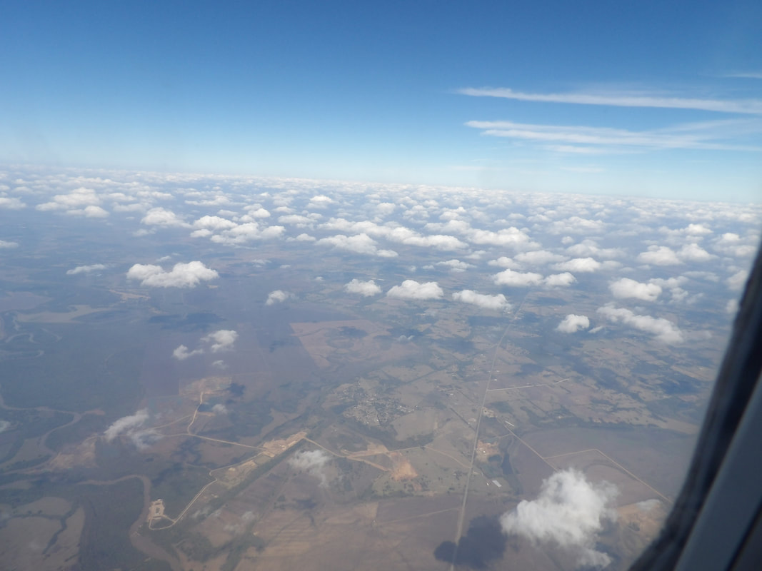 Flying over the US. 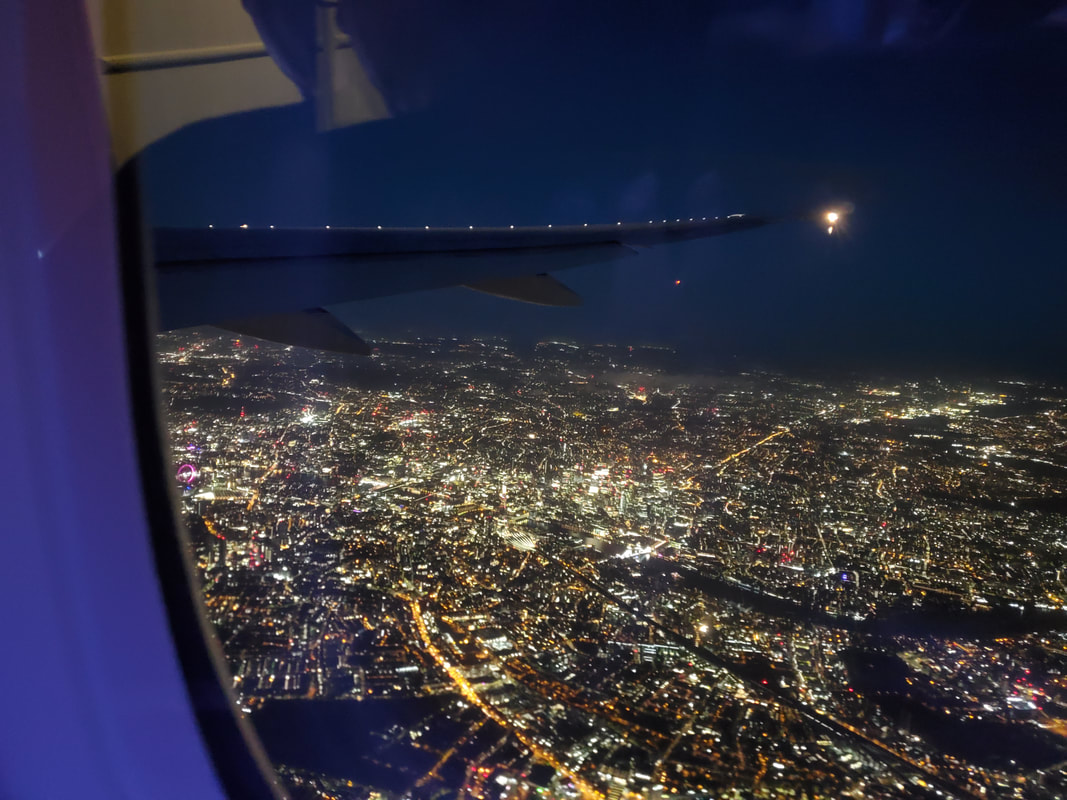 Flying over London early morning on our final approach to the airport. With us in the UK and through the airport, we have to make way to the hotel, which is not far as miles are concerned, but traveling through London is like traveling through Chicago, it takes a long while just to go a few miles. Not knowing how to navigate the vast subway system, we immediately opted for a cab in order to get to the hotel as well as take in the city from the roadways. 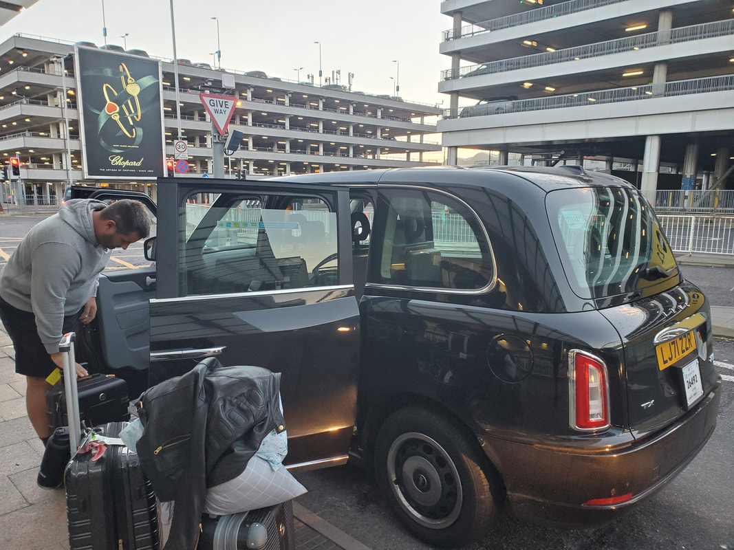 Getting our junk loaded up into one of the famous black cabs, not sure of the model of this car but its pretty much made for transporting a large number of people. 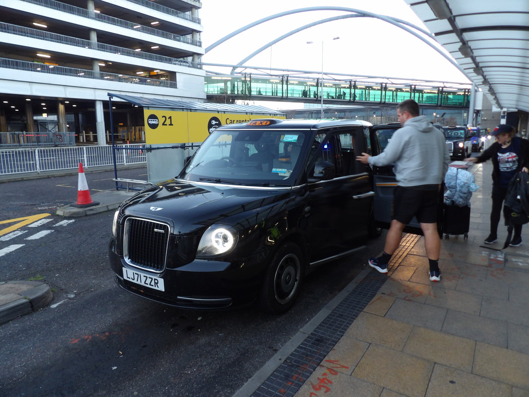 Loading up in the cab at the airport. 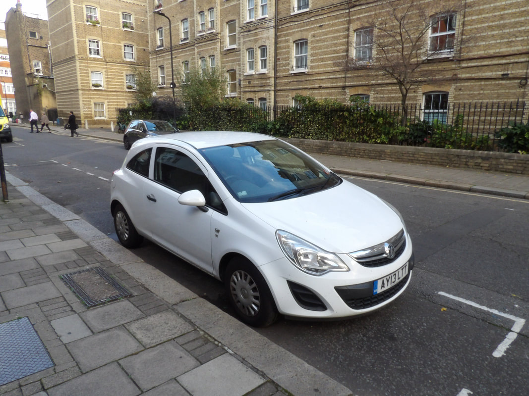 A little 2 door hatchback that looked pretty cool. Make/model unknown. 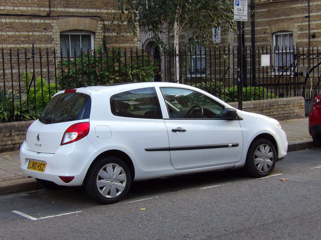 Another 2 door hatch, can't really make out the nameplate on the hatch. After making it to the hotel and actually being able to get an early room, we cleaned up and hit the street, taking the subway to go see Buckingham Palace. we did get to see the changing of the guard as they marched by, going into the palace, but due to restrictions we weren't able to get up close and personal like others in the past. It was still cool to be able to witness everything, even from a distance. Once we seen that, we took a walk down the street to the Guard's museum, which was a smaller facility displaying a lot of items collected by the soldiers that make up the guard through the ages, along with uniforms and other memorabilia. A lot of information was also displayed for people to learn everything there is to know about the Royal Guard. 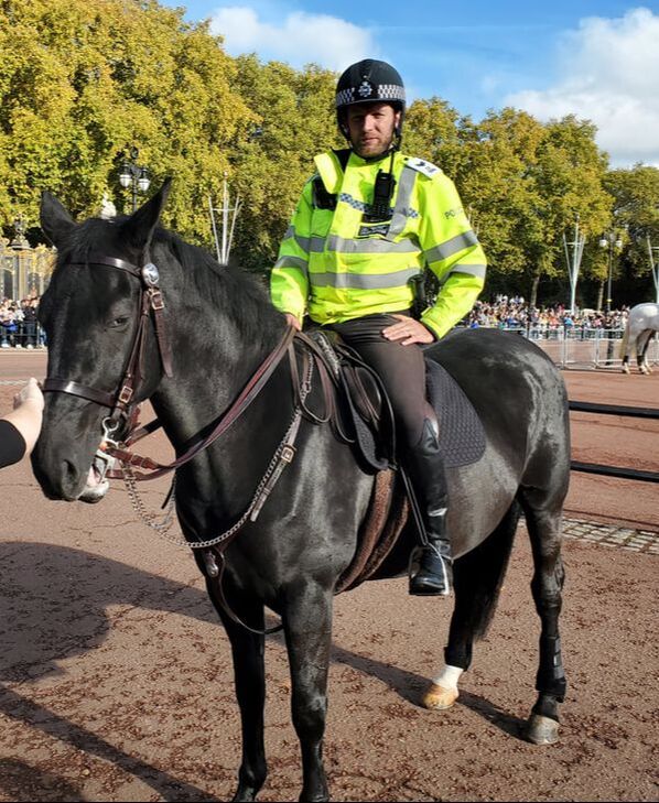 One of the mounted police overseeing the area as the crowds were rather large in front of the palace during the guards' ceremony. 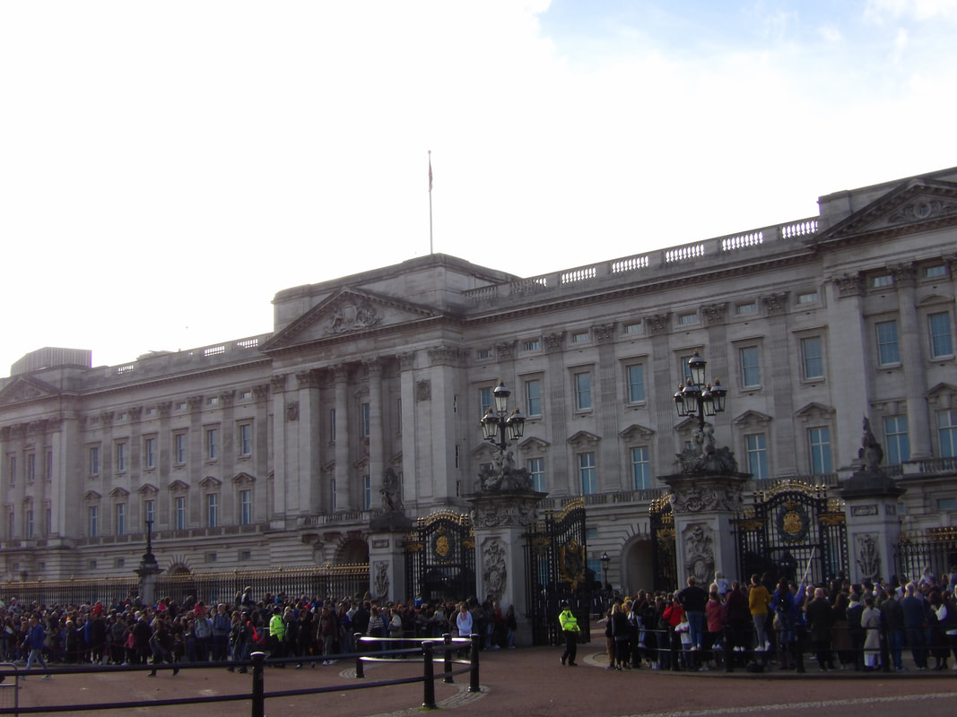 In front of Buckingham Palace during the changing of the guard. 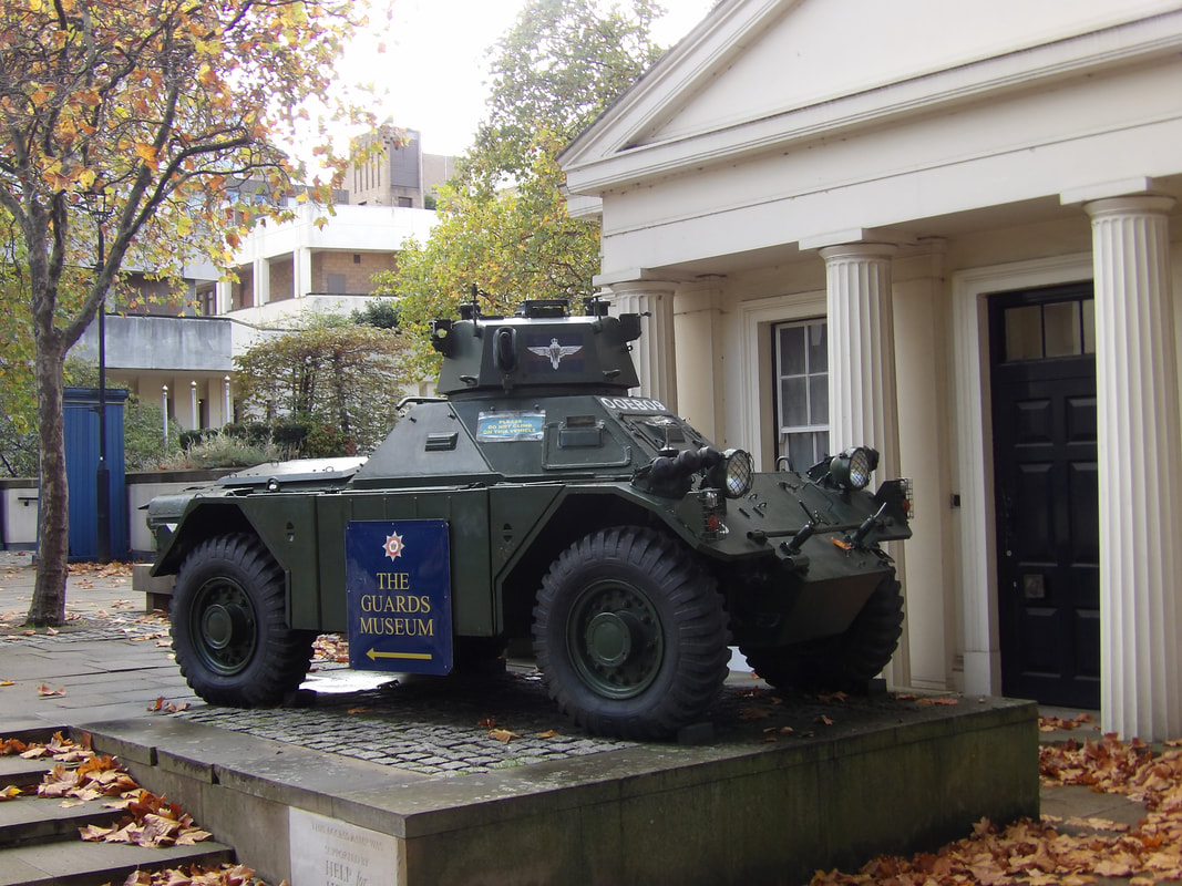 An armored car displayed just outside the Royal Guard's museum. 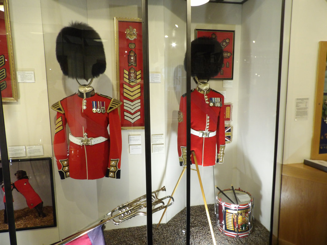 The iconic Guard red jackets and bearskin hats. The differences are subtle and indicate the particular grade of unit based on the medals and insignia. 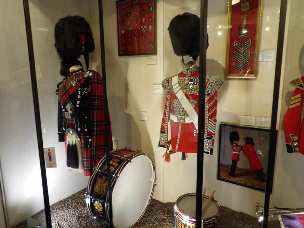 Guard uniform jackets for the specific units of Guard. 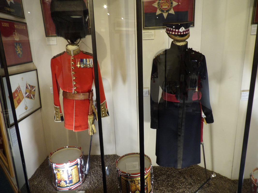 More Guard uniforms for the particular levels of Royal Guard. 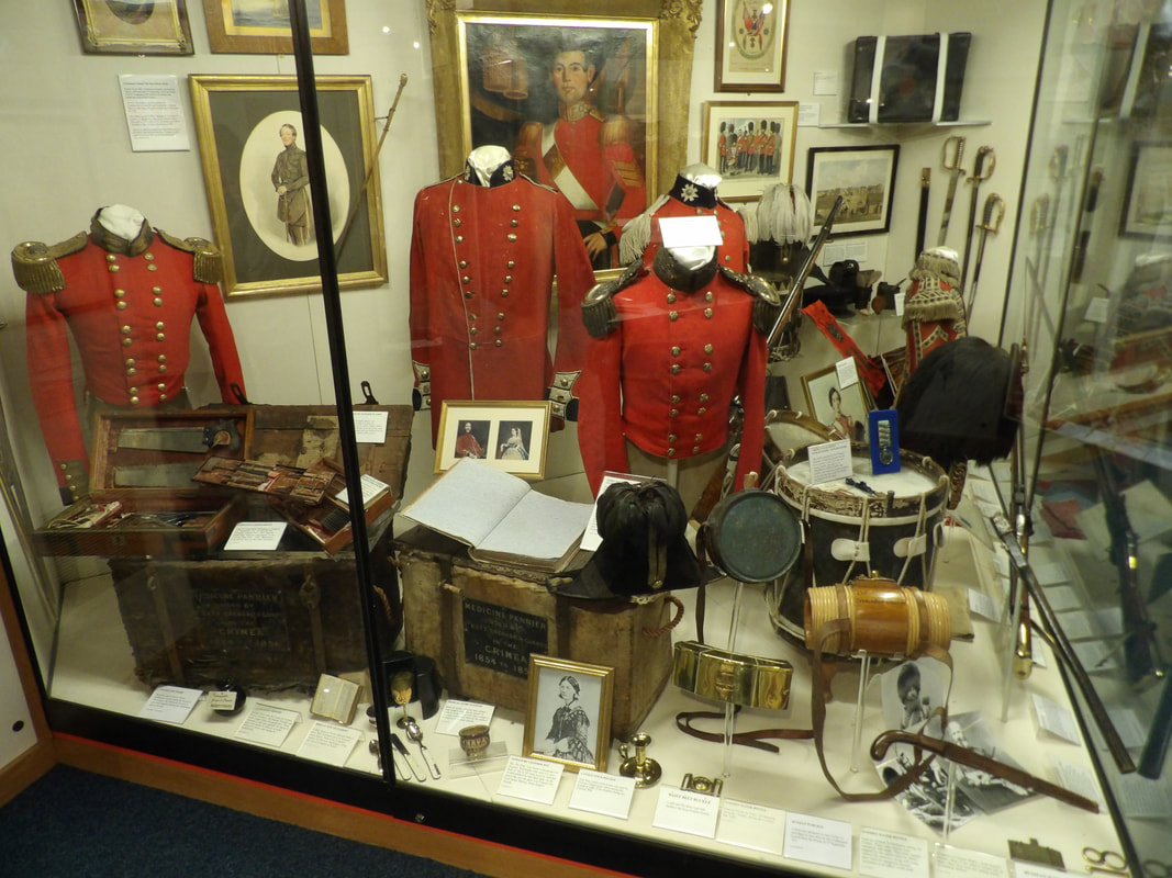 A large batch of Guard memorabilia on display. 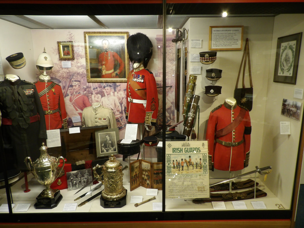 More Royal Guard memorabilia. 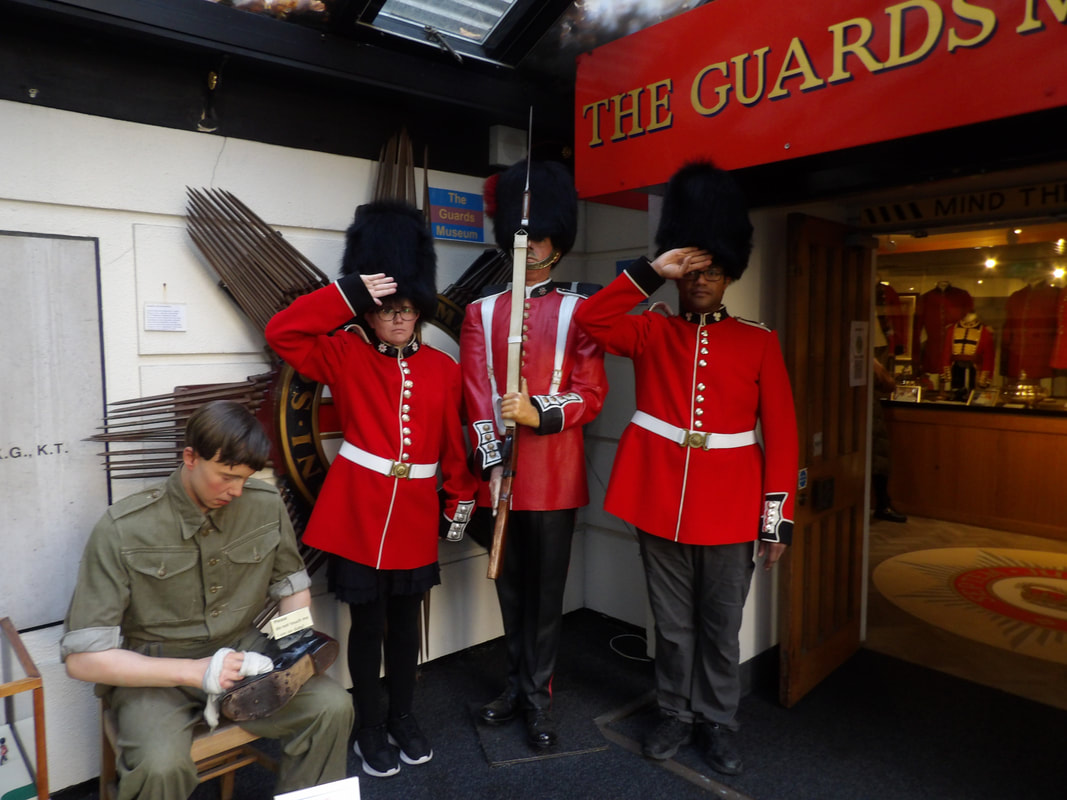 Posing in a couple mock guard coats for a picture. 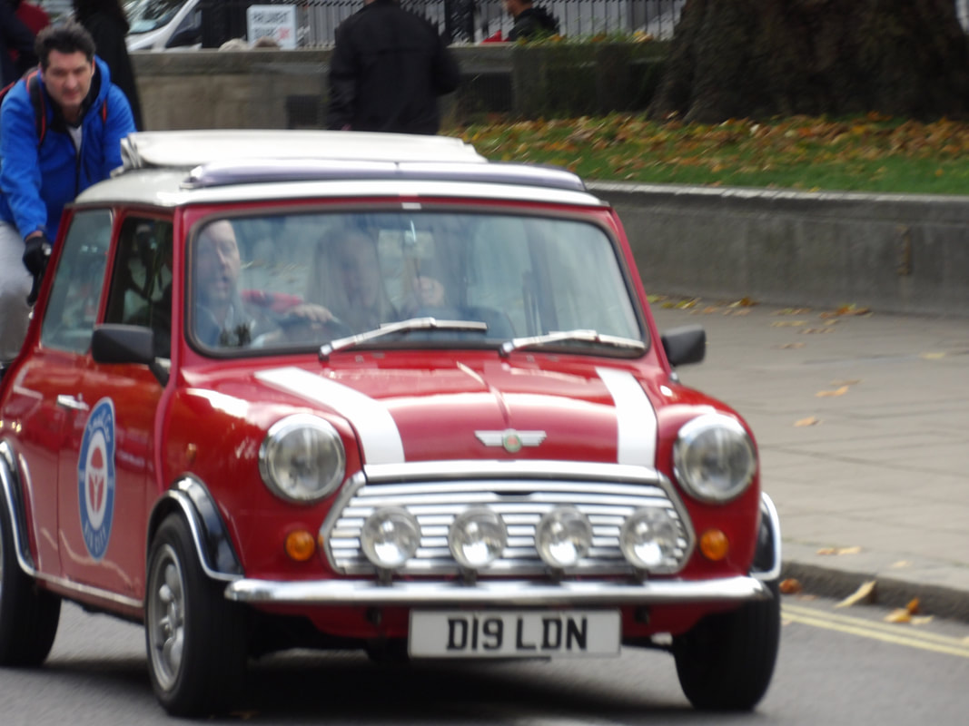 A mini cooper car riding by. We got to walk by other tourist areas on the way to the River Thames, namely Big Ben, which was unfortunately closed due to renovation and House Of Parliament. We eventually made our way to the river and the London Eye, the iconic Ferris wheel that takes you way up in an enclosed gondola overlooking the city. Even though the wheel only makes one full rotation, you're in the gondola for around 30 min during the whole ride, able to take a lot of pictures of the city from up high. We also got some Fish and Chips along with roasted caramel nuts and mushy peas, all staples of the land. 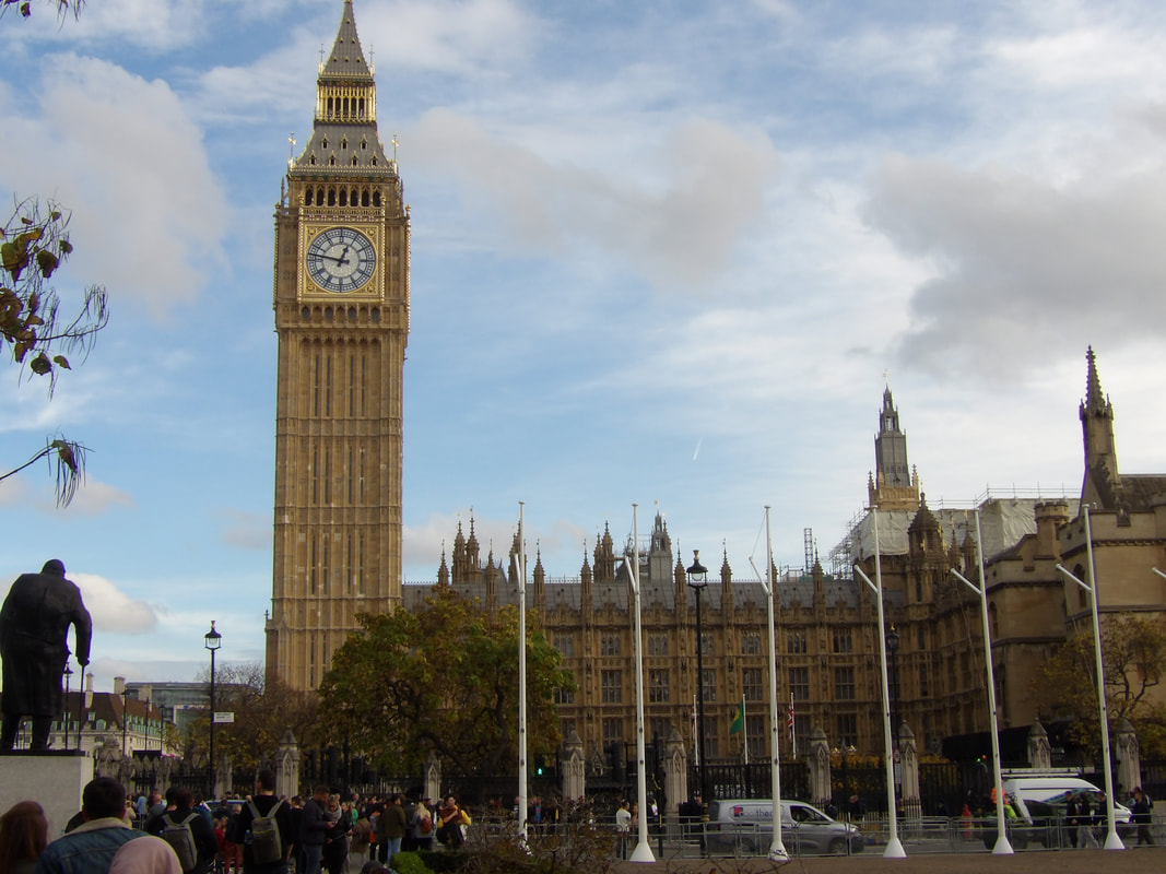 A shot of Big Ben as we walk towards it and the River Thames. 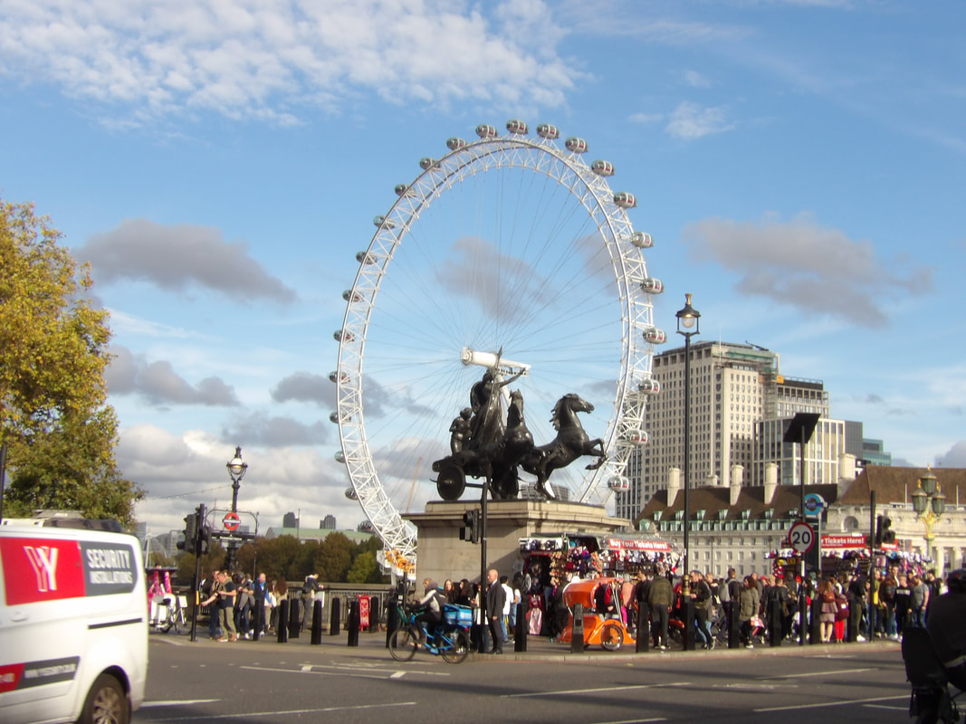 The huge London Eye Ferris wheel. 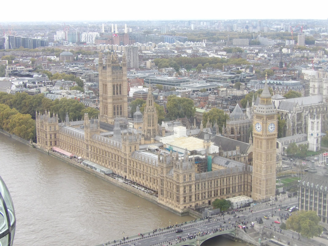 An aerial shot of Big Ben/House Of Parliament from the London Eye gondola. 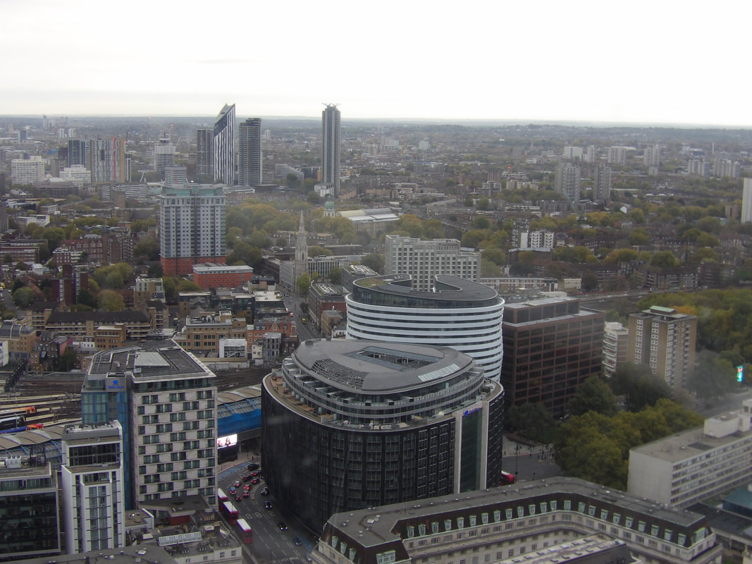 A shot over the city from the gondola on the London Eye. 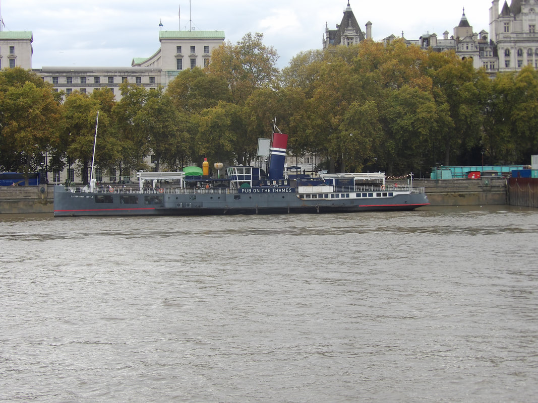 Pub On The Thames, built out of an old ship. After our long day out and about and managing to take in several tourist stops, we made our way back to the subway and back to the hotel. It didn't really take long to learn how to use the subway system so we would be able to further navigate the city through the subways to be able to get to other tourist spots in the city without ever having to take a cab, much less walk a million miles. We got a little something to eat to take back to the hotel since we were running on fumes. Despite having gotten a multitude of naps on the plane, it wasn't the same as getting a good full night's sleep in a regular bed. We pushed on through the day and made it to the evening, with the end being a hard crash around 7pm UK time.
I had a problem getting the taillight on the right side to work, later finding out that the housing and socket were rusted/corroded to the point that they wouldn't even conduct electricity to make the light work. There's obviously two options, one is to buy a new taillight socket, which is a viable option as the parts aren't too expensive, or, improvise as we always do, and make things work with what we have available. Obviously we tend to always go for the latter. Luckily I had some light sockets on hand that were pulled from some other car or whatever, I don't remember where I got this stuff from. I ended up chopping out the old light socket from the housing then trimming the hole to allow for the replacement light socket to be put in place. Because I couldn't get the measurements down perfectly, the socket didn't sit snug so I had to add a piece of metal to act as a retaining bracket to hold the socket in place. With that all done, I was able to remount the taillight socket in the car and wire it all in, allowing me to finalize the taillight/turn signal/brake light circuit.
Taillight housing mounted back in the panel and wired in place, ready to go, note the bent bracket used to hold the light socket in place.
The next order of business was installing the retro radio that I had ordered for this car. The radio has a face that makes it look like something you'd see in an older car but it's a bluetooth connective media player that is low profile so it doesn't take up much space under the dash. I had already routed the constant and switched 12v power wires to the hole but still had to add speakers. Since I didn't want to clutter up the interior with more wires by installing speakers in the panel in the back seat area, I decided to install smaller speakers in the dash body in holes that grace either side of the larger hole that would be used for the defroster vent tube. I had a couple smaller speakers, one of them a 2 way and the other a regular speaker. I had to drill extra holes in the dash surface to allow me to use a couple screws to secure the speakers. With the speakers in place I was able to go ahead and wire in the plugs for the radio. 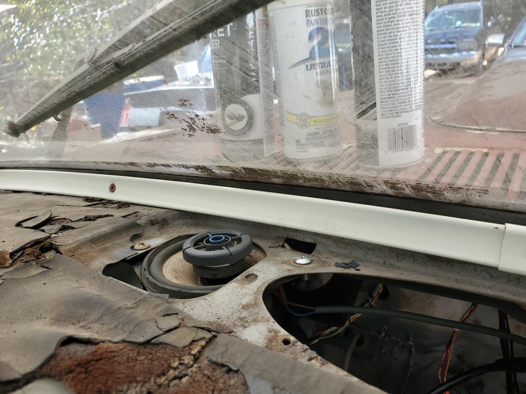
The 2 way speaker mounted in the dash body, crude and temporary.
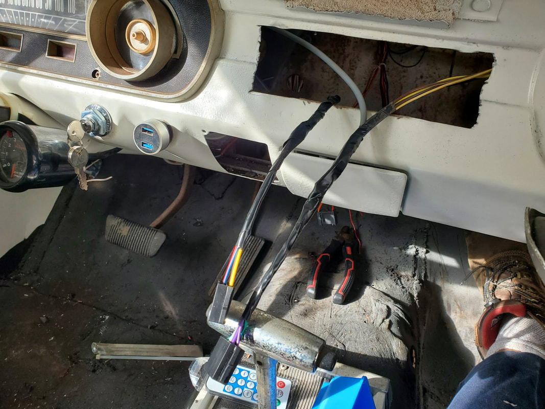
Power and speaker wire harnesses from the radio wired in place.
With the wiring taken care of I was able to install the mounting body for the radio, which just uses some tabs on all four sides which are bent out to lock the housing in place. The hole isn't perfect so the housing has some play, but it won't just pop out at least. I plugged the wires up and locked the radio in place. It does seem to fit pretty good in the dash of this classic car interior. 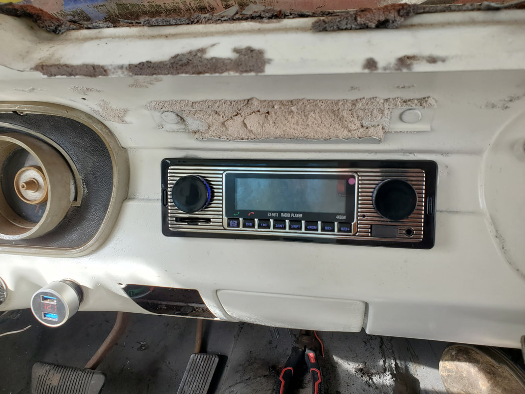
The retro radio snapped in place in the dash, ready to go, even with just one speaker. I do still need to install an antenna if I want to actually listen to a received radio station.
After going through the process for setting up the bluetooth connection to my phone, I had the radio successfully playing...through one speaker, the 2 way unit. The other speaker was trash. All this means is I'll have to replace that unit, but then again, I have to do some research to see what combination speaker/amplifier devices might be available that would allow me to install a setup where I could do away with even the small 2 way speaker and just have a nice boosted speaker in place somewhere under the dash that will do just as good a job of blasting out sounds as any 6x9 speaker. That way I can keep the under dash area a little cleaner without the addition of extra speakers. We'll see how we can arrange that.
Just for shits and giggles I decided to bring down the components that make up the rear seat on the Truckstang. I wanted to try and see if things would fit in some way since the side panels have groves made to hold the outer portion of the seat body. There was a rear most panel that went behind the seat assembly and goes partially under the speaker panel. That panel fit just fine. I found that the seat body was indeed able to fit just fine between the side panels. Of course, I had to see just to satisfy my curiosity, if the seat bottom would fit. It wouldn't. The floor's new position would not allow for it. But it's fine, With the seat body in the closed position, the interior at least looks a lot better and can at least serve some kind of purpose in providing a solid surface to store items. Without knowing, you'd think that the interior is the same as a regular Mustang, until further inspection would reveal the truth of the matter. 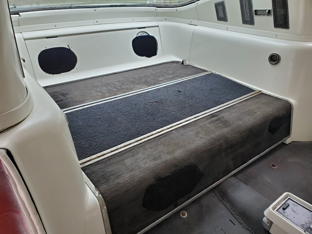 The rear seat components bolted in place after a test fitting found that everything except the seat bottom would fit just fine. Now for the other stuff. After analyzing a number of things around the homestead, I started making some plans for some serious changes. On the lighter side, I did take a moment to move the four drums I used in the Truckstang project over to the 51 Chevy, since that would be the next truck frame swap that'll be done. I will end up working on the 46 Ford before this one, but that car body is already on a truck frame and won't need any propping up.  The four drums staged behind the 51 Chevy so when that project begins I can set things up to suspend the body on the drums and boards. After Truckstang is done, I plan on starting work on the 46 Ford, since I have most of everything I need to really make some progress on that build. I had another project in store for the Dodge I plan on starting in the very near future, plus I had to finish things up with the DOB and the FMT. Once those vehicles are done, then I can start work on the 51 Chevy, which as of right now, the current plan is to use the S10 as a donor for the truck frame and powertrain. Another thought that had been bouncing around through my mind is the idea of building more truck frame swap vehicles, but of course cool vehicles. I would have to find a donor vehicle I could use that lends itself to a direct install on a truck frame. Since short bed Ranger/S10 frames tend to fit Mustangs, it only seemed logical in my mind to do this type of build again. Of course I plan on doing this with the Rustang, which has the same wheelbase as the Truckstang and other vintage Mustangs up to 1973. Because of this, this means that I started looking at the Mustang Chicken Coop. Even though the car had been mortally damaged when two trees fell on it, I was able to do a crude straightening of the roof to allow me to build out the chicken coop to look like a more or less viable car again. I had the wild idea of using this car body as the donor for Truckstang 3, shitty roof and all. The whole idea would be to make something that you would definitely see in a post apocalyptic movie. I even thought about cutting out the back section, including the window, and making the whole area into a truck bed, which is like the character cars in the game Mad Max. The next thing I would also do with regard to the build is use all the running gear from the donor truck. If its a Ranger, I'd want to use the 2.3L 4 cyl and hopefully a 5spd manual transmission. If its an S10, I'd be rocking the good ole 4.3L V6, again hopefully with a 5 spd manual. Reason behind this choice in the build is to produce a car that mechanically from top to bottom, is the donor truck. This type of restomod would give one the pleasure of driving a classic car or something they build that's unique, while having the convenience of a modern enough vehicle that has ready access to parts. 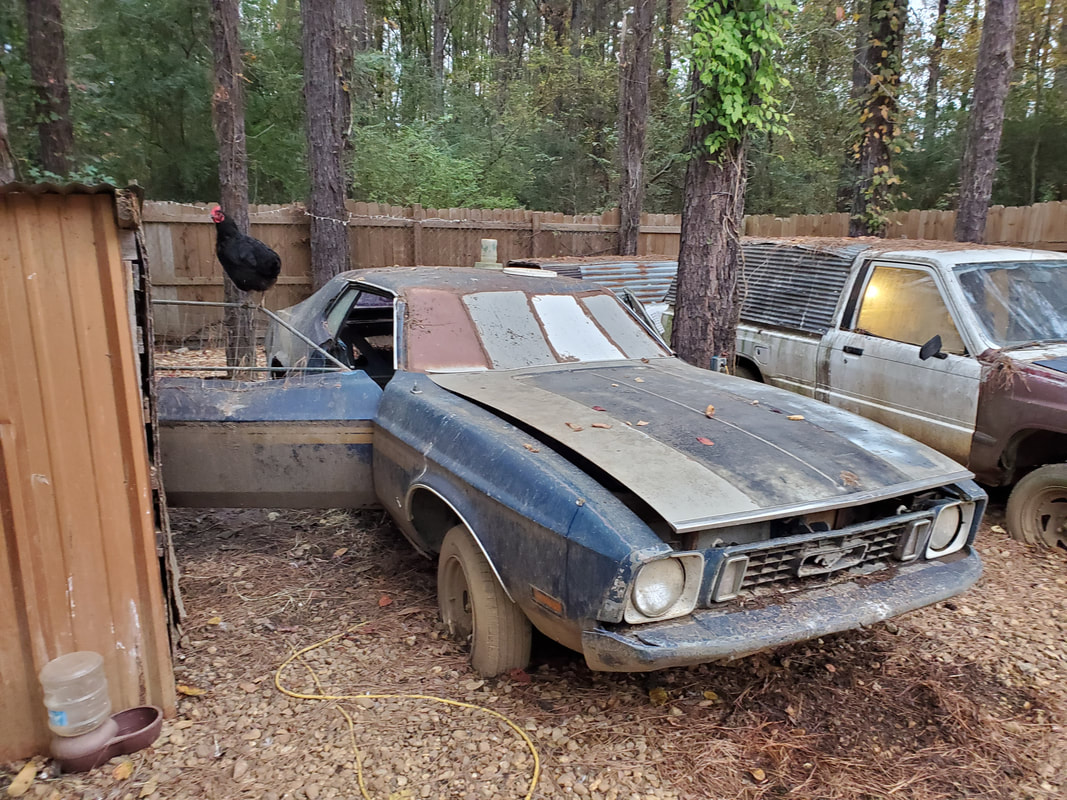 The Mustang Chicken Coop, a 1973 Mustang that sustained heavy damage from falling trees and as a result was converted to a chicken coop. Will it possibly see the road again? The way my mind works, it may very well hit the road again. Of course I'd have to replace a lot of the parts that I still have for the Mustang if I do plan to build this car back out. I still have the dash frame and some trim pieces from the dash. I'd still need the gauge cluster, seats, and a shifter. Since the roof is still pretty crinkled up, I'd end up using lexan or plexiglass for a windshield if it doesn't look like I can get the window frame straightened enough to accept a new glass. Of course other things like the doors, fenders and other panels would need repair or replacement. I'd end up doing the body work on this vehicle in the same way I did Truckstang, welding crude patches in places. We'll see, we still have plenty other cars to build. On the other end of the spectrum, I thought about the remaining area of the compound that I have on the south end of the area. This wide open area is home to the fuel shed, the future storage building, some parts/scrap metal racks (some of which are falling in on themselves), a large batch of scrap and car parts, and some trailers. I had a new plan to basically close this area down. First I'll work on scrapping a lot of the car parts and scrap in the area, the stuff I can't really use. I'll be constantly trying to build with the other raw materials to try and use up that stuff as well. As I clear these racks, I can dismantle the ones that are almost clear and relocate the remaining materials to a new location where my storage would be more streamlined. The two kayaks we had on a rack along the south fence with the scrap parts would be staged vertically, most likely along the northwest fence line, behind the 51 Chevy. This area would be the planned area for where I want to build out the new storage garage as well. 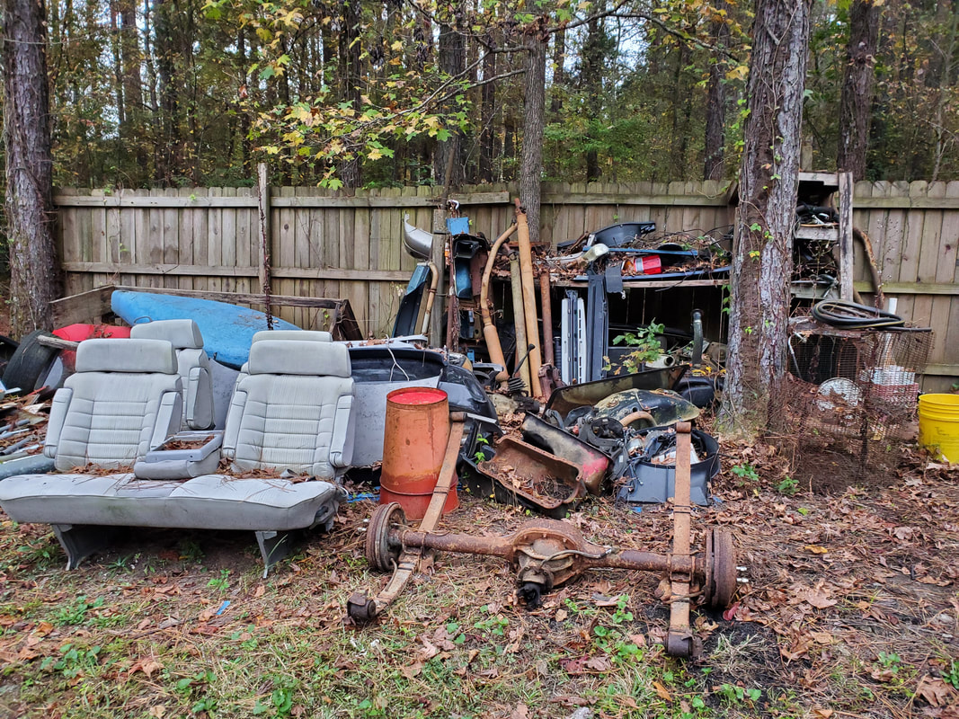 The scrap auto parts and other crap staged on different racks along the southern fence, soon to be sorted through and moved from this area. I plan on dismantling the frame of the storage garage and rebuilding it, in a smaller size, in the northwest corner of the compound. The contents of the garage will be planned out so we can capitalize on the space and not just have a humongous structure. I may very well get rid of some stuff and take advantage of vertical storage for certain things. Point is, the garage will be smaller and as a result, easier to build, with a lesser use of resources. Once the storage rack and garage frame are cleared from the west fence, and most of the crap along the south fence is removed/relocated, my plan then will be to dismantle the fencing along the south and the southwest section of fencing, using the fencing to finish up the fence along the eastern fence line and to close in the opening between the back of the garden fence and the back of the storage trailer. As for the fuel shed, I had two plans for that. One would be the simple act of partially dismantling the structure and relocating it to the firewood staging area. I plan on moving the firewood from the outer row and stacking it all on the inside row, along the chicken yard fence and setting up the fuel shed in the northeast corner of the compound fence. The other option would be to build a shorter structure, around 4-5ft tall, and stage the fuel drums next to each other, with four drums being side by side and a small locker or cubby set up on the outside to store the fuel cans, propane tanks, and other miscellaneous fuels. Whichever option I chose, it will be set up in the firewood staging area and the fuel shed as it stands will be removed from the southwest corner of the current fence. 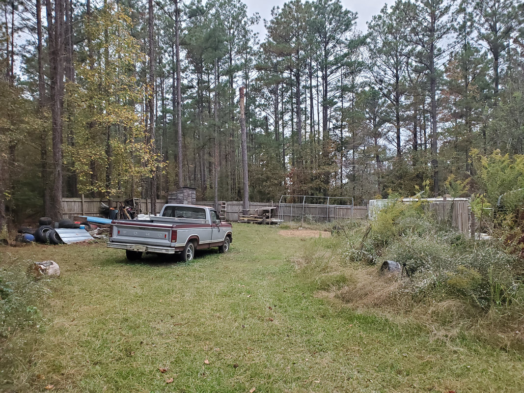 A shot from the eastern fence line showing the expanse of the back area, with the storage garage frame visible in the distance. All of this will be removed to open this area up. By closing in the section of fence line between the garden fence and storage trailer, the construction of a garage in this side path would not obstruct anything. With the removal of the fencing around the old areas I'll be able to move vehicles and rolling stock from the main driveway around to the "back" area, along the eastern fence line. The trailers noted earlier, along with the car trailer, which is parked along the main driveway, would all be parked along the eastern fence line with security locks on the hitches and tires to prevent theft. The area will be plenty wide enough to make the necessary turns to move trailers in and out. Depending on circumstances, I may still be compelled to lay gravel down over this area so vehicular traffic can be conducted without getting bogged down in mud.  A shot from the back area looking at what will soon be the new southern fence line. A small section of fence will be set up to close in this area between the garden fence to the right and the western fence, just behind the storage trailer. I will have to pull the storage trailer forward a couple feet so it will clear what will be the fence line. The biggest part of making this decision is the idea that it would allow me to finish the compound fences way ahead of schedule, since most of the salvaged fence will cover the eastern fence line and the gap between the garden fence and storage trailer. Other than having to maybe buy one or two whole panels and pickets for the eastern gate, we should be able to get the perimeter fence done. I'll still have to do the rest of the fencing for the garden itself on the inside, and of course the main gate, but I have plans surrounding that just as well. Everything in the area will be relocated and staged in a way where I take advantage of all space within the compound fences and also get rid of more stuff deemed useless or otherwise unnecessary.
The next thing that managed to show up in the mail for the Truckstang is the radiator fan. Because this radiator is smaller than the radiator used in the Rustang, being able to cool the 289 V8 is very important. Since the position of the engine relative to where the radiator sits would cause the water pump mounted fan to hit the top rad hose, I had to remove the fan from the water pump. Obviously I'd have to use an electric fan, and use the biggest one I could install. In this case, I picked a 16" fan, compared to the 12" fans I used on the Dodge. This large fan managed to cover approximately 80% of the surface of the radiator. This fan should be more than able to draw enough air through the radiator to supply the vital cooling for the engine. Before the fan came, I did get the wiring taken care of. Since the amperage draw is high enough to be a little taxing on the spartan electrical system, I chose to use an automotive relay for the fan, which will get power directly from the battery, with the relay being switched from the electrical system. This makes things easy to bypass if the relay happens to malfunction but I would like to think I'd keep a spare relay in the glovebox or whatever I plan to set up for storage in the car.
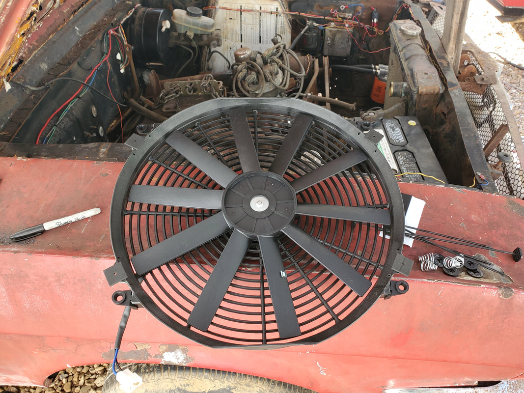
The huge 16" electric fan that will ensure the longevity of our classic 289 engine.
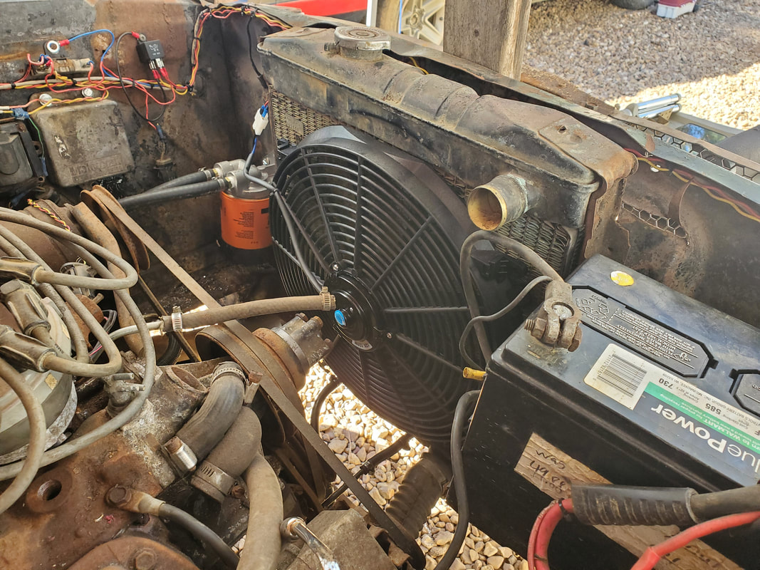
The radiator mounted on the fan, showing just how much area is covered by the fan.
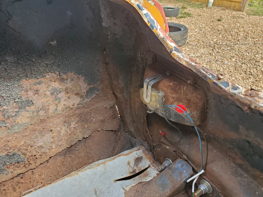
In the meantime, I did take some time to test out the different circuits on the car. The headlight circuit, wipers, starter, etc were tested successfully. I did have an episode with the turn signal system as it was popping fuses constantly. After a good day of aggravating troubleshooting, I found that one of the front parking light assemblies was wired wrong and essentially shorting every time the signal switch was activated. Ironically the other parking light was wired the same way and didn't pop fuses, which was confusing. I did rewire both lights, solving the problem with the malfunctioning turn signal/hazard light circuit. Another problem I had in the circuit that was less of a problem and more of a headache was the fact that the right taillight did not work. I ended up using the additional light socket I installed on the housing in the past for a turn signal just to test the operation of the turn signal system now. I would have to repair this by either replacing the housing/socket or in TIC style, making something work. 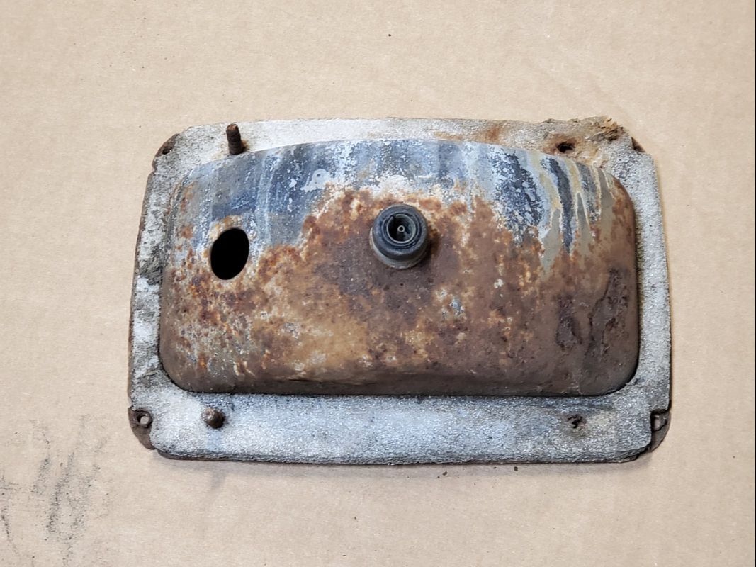
The old rusty taillight socket with the hole from where the extra light socket was plugged into.
I had the spare light socket added because trying to resurrect the original turn signal circuit where it switches between the brake light, fed off a constant 12v power source, and the turn signal, fed from a switched 12v power source feeding through a flasher module, would involve replacing the entire turn signal switch/cam assembly, which is a pain in the ass. It was easier to just add another light socket, separate from the old wiring, and isolate the turn signal cam switch for use in switching the extra lights. Now, with the universal signal switch, I can go back to the single dual filament bulbs in each taillight socket, as it was from the factory. To help this along, I cut out the old light socket from the housing, then trimmed the hole to accommodate another light socket I pulled from another car from the junkyard a long time ago. This socket will then be wired into the wiring I set up, allowing the signal/brake light circuit to work as intended. 
The light housing after cutting out the bad light socket and trimming the hole to hopefully accommodate the "new" light socket.
Because I wasn't exactly able to get the measurements for the light socket and the hole that I would need to cut, I ended up cutting the hole too wide. While this would be a setback for some, because we're TIC, we make things work. In this case, I took a piece of metal that appeared to be a lever of some sort for a switch, I don't even know where I got it, and bent it to serve as a retaining clip. I drilled a hole on the housing and secured the metal piece with a sheet metal screw so it can hold the light socket in place firmly. 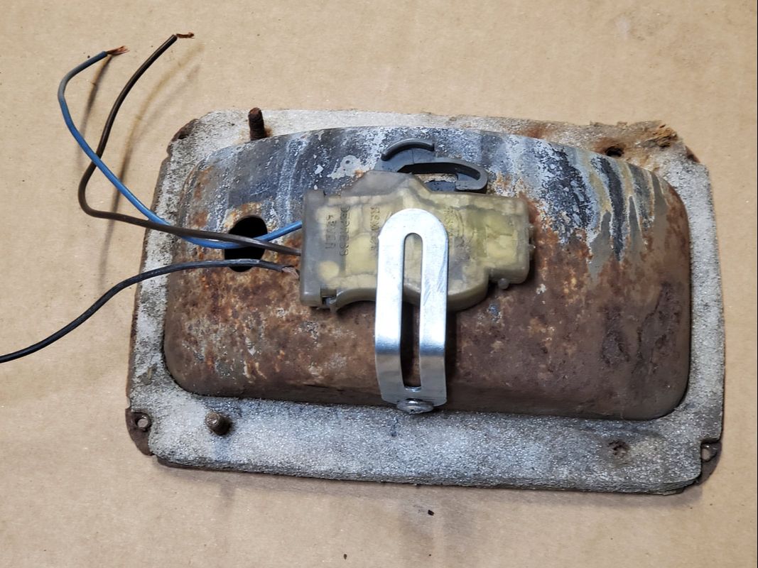
The taillight housing with the different socket in place and the metal retainer screwed in place to hold the socket firmly.
With the socket modified and now "working", I can get the piece installed back in the car and conclude the turn signal/taillight/brake light circuit on the car, which will then put me in a position where I can't do anything else on the electrical system until I get more components in. The next thing I'm waiting for is the radio, which is on order and is of a retro style but is a digital media player, smaller in size, lower power consumption and bluetooth ready so it can connect to a phone for use. The next thing I will have to do is source a couple of small 3 way speakers to use in the dash right above the radio, versus running two pairs of wires all the way to the back, which will just be more clutter in the car. Of course, this also means I'll have to plug the holes in the old speaker panel to clean up that area. This will most likely be done by cutting some sheet metal and tack welding said sheet metal in place over the holes then painting the new surfaces with the Ivory Bisque paint I used on the rest of the interior.
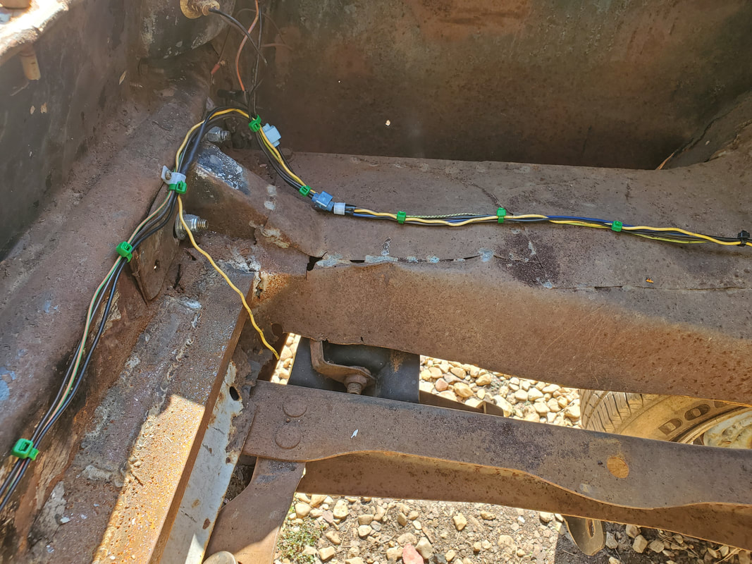
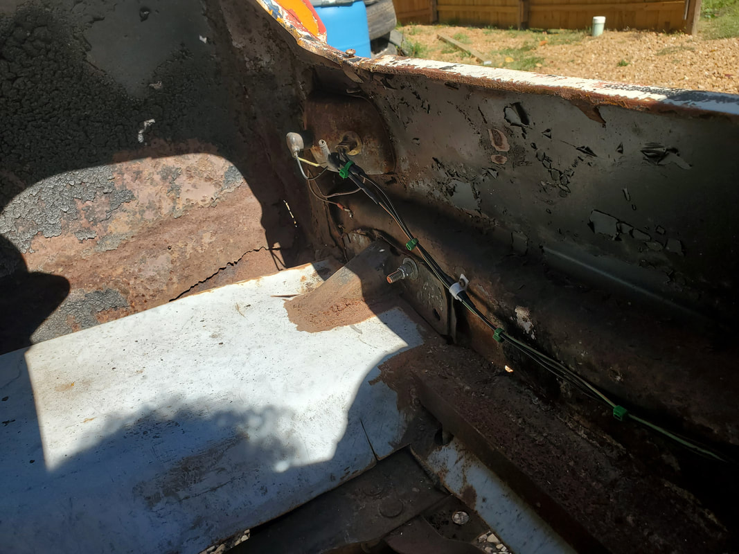
At this point I'm in a position where I won't be able to do anything else to the Truckstang's electrical system due to the fact that I have to still order some key components for the car's system. Things like the HVAC boxes, radiator fan, fuel tank sending unit and H4 headlights need to be ordered. This doesn't stop me however, from running the wires for these loads over to their respective locations so once I get those components and mount them, all I have to do is just hook the wires up. Little by little this will get done as these components are some of the pricier components. In the meantime, I did take a moment to go ahead and hook up one more component that was part of the batch of stuff that was planned to be used on the car. The tachometer, a vital component in tuning the engine as well as monitoring its performance, is that component. Because the universal turn signal box was mounted on the left side of the steering column body, the only valid spot to mount the unit is on the right side. Because the column is mounted farther in under the dash, there isn't enough of the narrow portion of the column shaft available to mount the tach. I had to mount the thing almost straight across from the turn signal box. Again, long zip ties came into play to secure the tach due to my not having a large worm clamp, which I also need to use for the securing of the turn signal box. 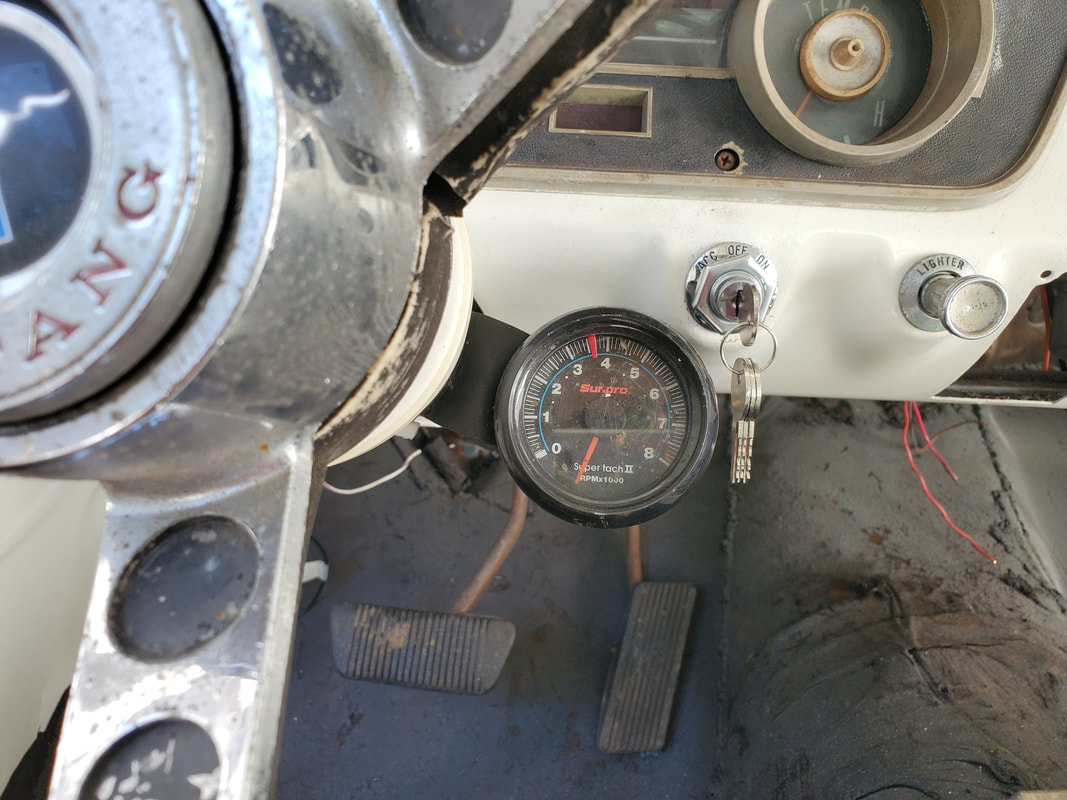 Universal tachometer mounted in place against the side of the steering column using a zip tie. With the tach in place, I went ahead and zip tied the wire bundle along the steering column tube and along the same path as the other wire bundles under the dash. I hooked up the gauge light, tapping into the gauge cluster light circuit and securing the power line to the switched 12v line feeding the gauge voltage regulator and the ground to the bolt holding the regulator, which then goes to chassis ground. The tach feed line was routed through the firewall to the engine bay so it can be hooked up to the dizzy. While I had the gauge cluster out I also took a moment to route a switched 12v power feed from the same point on the voltage regulator over to the radio hole. I tapped another line from the cigarette lighter to feed the constant 12v line for the radio. Once the radio comes in all I have to do is hook those power lines to the wire harness, and of course the speakers. I do plan on seeing if there's some smaller speakers that I can use to mount in the top of the dash in two spots that grace either side of a larger hole that will be used for a vent tube from the universal HVAC box to blow onto the window as a defroster vent. Doing this will negate my having to run a whole other batch of wires to the rear to cover two speakers that would've normally went into the back panel that held the old speakers. 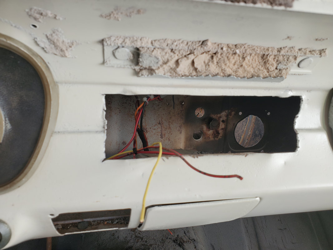 Pair of wires for the radio once its mounted. Yellow is constant 12v and red is switched 12v. With everything pretty much done as far as big wiring, I did take a moment to put the interior panel back on along the side just under the dash. Getting this out of the way and taking a moment to clean up the area will go a long way towards the completion of the rewiring. With the internal wiring done, the next thing that I needed to do is make a battery tray. The old battery tray has long since rusted away and the remnants disposed of. Luckily, I had a homemade battery tray made from angle iron that I used in a past project that would work in this application just fine. I did have to trim a couple pieces of metal from the tray and reweld them after fitting the tray. I did end up welding the tray a little too far in against the core support and fender wall. This pretty much prevented me from using the typical class 24 battery that I would've normally used in the car. I did check out the side post battery from the S10 to see just how it would fit and found that it will work in this application just fine. At least I can say that a GM side post battery with the additional lugs screwed into the terminals will work, as this same arrangement is used on the S10. These batteries are widely available so I'm ok with this arrangement. Now the next move is to start testing the system to make sure everything is working properly. 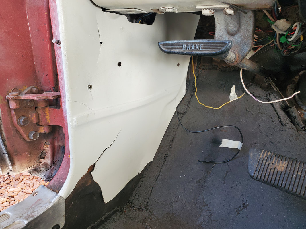 Interior panel mounted back in place on the side after finishing up the routing of the wires. 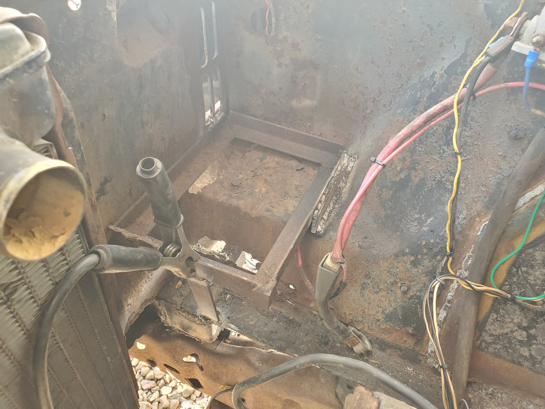 Homemade battery tray welded in place in the location of the old battery tray. Even though I can't fully mount the class 24 battery, I could still set it up enough to connect the battery terminals to test things. I also had a USB charger with an integrated voltage meter, which I plugged into the cigarette lighter socket. The battery was reading 12.4 v and one of the interior lights came on as intended with the doors opened, and went off with the doors closed. The key switch turned on the fuel pump and the alternator warning light, which will be on when the alternator is not charging. Attempting to crank the starter yielded me a successful test, also proving the engine was nowhere near frozen and everything else associated with the engine was working fine too (solenoid, starter). Headlight circuit also worked. Even though I don't have the H4 sockets, I could still plug a set of LED bulbs to the plugs to test the circuit, successfully, I might add. The problem area I had was with the turn signal circuit. The cheapo switch assembly currently has me running around in circles because at one point the left lights worked, then the right side would pop the fuse. After playing around with shit I would get the switch to activate on the left and right sides, but then the hazard light switch would pop the fuse. Now I'm at the point where the two sides activate on the switch but no outside lights come on and the hazard switch still pops the fuse. I have to investigate this to determine if this is a case of a faulty switch or if I'm missing something on the circuit. The fuckery continues.... As we continue with the advanced stages of rewiring on the Truckstang, we get to the point where we have to start adding devices that will be used on the car. Since the old HVAC box was trashed, it is one of the devices that will have to be sourced from the aftermarket and adapted to fit under the dash on the car. In the meantime, the wires for the blower are routed over to the area where the HVAC box would end up. The same goes for the electric fuel pump I ended up having to add. Because the fuel pump cam is missing on the timing gear/camshaft, I would have to go with the electric pump until I can manage to pull off the timing cover to replace this vital piece to allow me to install a mechanical fuel pump once again. In the meantime, I would have to get a wire routed over to where I would want the fuel pump to be mounted. Now here is where a little touch of laziness comes in. Because I had already pulled the rear panel and the surrounding trim pieces off several times in the process of routing more and more wires along this route to the trunk area, I chose not to install the fuel pump in the rear right where the fuel tank would be. I can't install it in the front as the pump would strain more to draw fuel along the length of the car in order to pump it up to the carburetor. Only other viable option was to mount the pump on the frame rail about midway to 2/3 the way back. This allowed me to have the fuel pump in a very easily accessible spot for future maintenance, plus it allowed me to route a power wire right from the fuse panel, through the firewall, and down along the frame rail to where the fuel pump is located. 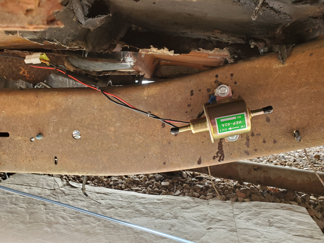 The electric fuel pump bolted up to the truck frame rail on the outside for ease of maintenance. Fuel lines will be connected to the frame rail along the same plane. Note the wires for the fuel pump secured under the floor of the body. With the fuel pump in place I went ahead and took care of the headlight plugs and the wiring for the turn signal lights. I had already routed a 2 conductor cable for the headlights when I was getting other wiring in place, so all I needed to do was just wire the plugs up to the wires. One of the terminals on the socket would be a chassis ground, and the other two lines would go to the two conductors of the cable for the high beam and low beam circuits. The low beam circuit would be routed straight to the output of the headlight switch, supplying 12v to the lights. The other would go to the high beam switch, which itself would be hooked straight to ground, as the high beam switch would be a switched ground with the H4 LED headlight circuit. With that done, I routed another two conductor cable, this time a twisted pair of red and yellow wire, along the same path as the headlight cable. The grounds on both turn signal lights were established and each positive wire was connected to one of the wires on the twisted pair. The twisted pair was routed through the firewall and over to the steering column where it will be connected with the new aftermarket turn signal switch when we do receive that piece. 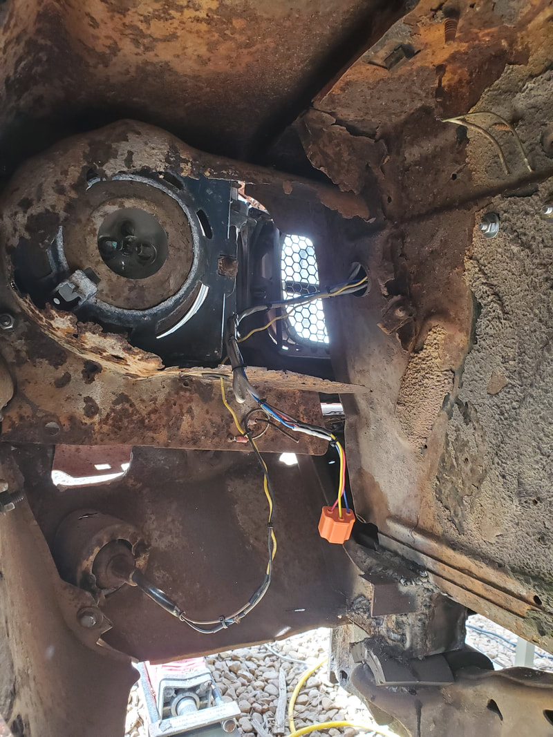 The turn signal light socket wired in place along with the headlight socket, also wired up with the wires routed up through the core support. The last thing that I had to establish was a circuit for the radiator fan. I would've used the pump mounted fan that was originally on the engine, but could not because of the positions of the radiator and the engine relative to one another. The engine sits a little higher, causing the fan blades to hit the top radiator hose, which we cannot have. Only option is to install an electric fan. Luckily the aftermarket comes through, supplying a 16" flush mount electric fan that even comes mounted on an aluminum shroud plate that fits over the radiator. While I haven't bought one of these pieces yet, I could at least get the circuitry established. Since a rad fan draws some juice, the only viable option I could do without having to add to the fuse box under the dash was to use an automotive relay. The fuse box would only switch the relay while the relay, being fed directly from the battery, would power the fan. I mounted the relay on the same fender wall as the Duraspark hardware, since I would pick up a switched 12v power source from the source supplying the ignition system. I used a connector on the ballast resistor allowing me to add another female wire terminal to the mix feeding the resistor. The terminal has the switched 12v coming in, along with the line feeds going to the ignition coil and now to the automotive relay. 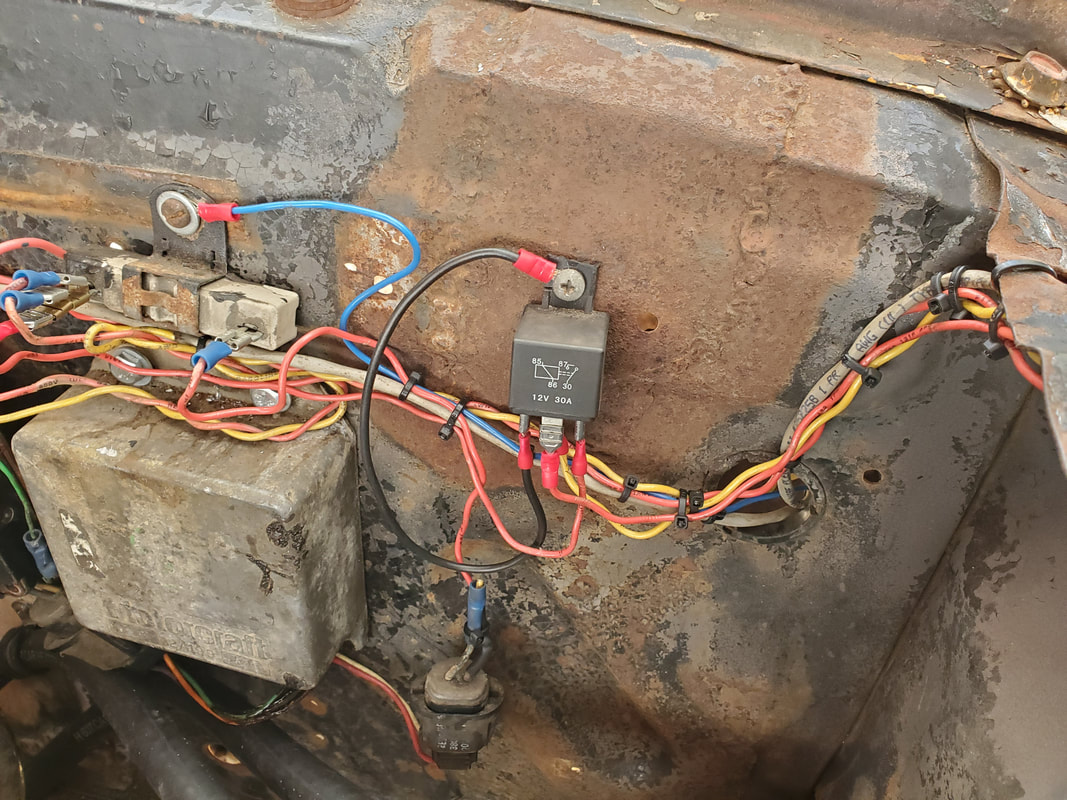 The automotive relay installed and wired up with the ignition system power. The 12v source from the battery was tapped with an eye terminal and hooked up to the starter solenoid where the battery cable is hooked up to. The wire was then routed along the same path as the turn signal and headlight wires, along the top of the radiator core support and over to where the automotive relay is located. After zip tying everything together, I used a short piece of wire to connect the ground side of the automotive relay to the screw that is used to hold the relay to the fender wall. A short piece of wire was then zip tied in place with the wires going over the core support, then routed down to the side of the radiator with enough free wire to reach the fan when we do install it. 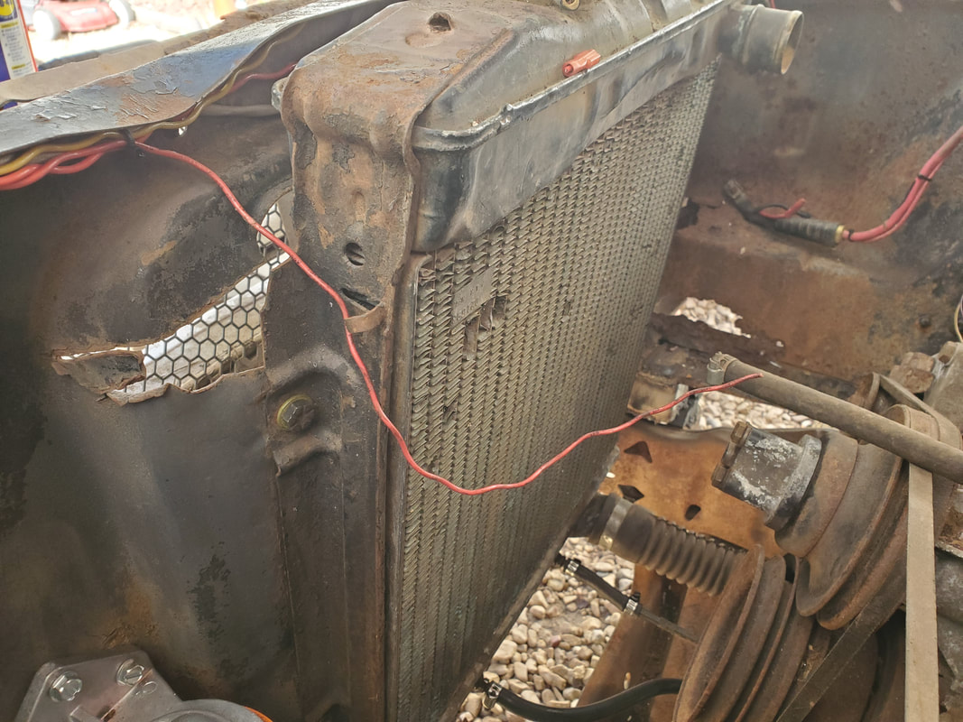 The single red wire routed over to the side of the radiator to supply 12v power for the radiator fan once it is installed. At this point I'm now at the crossroads where I'm waiting for resupply. Between the turn signal switch, the rad fan, the fuel tank with the sending unit, and fuel hoses, and the H4 LED headlights/sockets, I really can't do much else on the rewiring. I do have to make a battery tray so I can get a battery mounted and ultimately start testing the circuits to make sure that everything that is in place works, and that I'm getting power at the free lines that are routed over to the loads that have not yet been installed. As these items come in, I can finish up the rewiring and by extension, fitting out of the rest of the components on the car, coming that much closer to completion on this project.
At this point, I've gotten into the advanced stages of the rewiring on the Truckstang. I'm now in the engine bay, where I have to wire up the voltage regulator and the alternator, the Duraspark system, as well as a few other odds and ends that have a connectivity to the rest of the electrical system. I started off with the voltage regulator and the alternator by association. I had to get a schematic for the voltage regulator so I can get the wires right for the four terminals on the regulator itself. For now I'll be using the original 1G (1st gen) charging system until I can upgrade the system to a 3G system, which uses an integrated voltage regulator. Those alternators are typically in middle/late 90's Fords and is the same alternator that's currently on the Rustang.
Voltage regulator wired up to alternator with wires hooked up to starter solenoid.
With the wires all figured out I got the regulator wired up the alternator along with the other wires which were a ground and a power line from the switched 12v side of the circuit. I zip tied everything to neaten the wires up, as usual and even added some wire straps around the fender wall and firewall to route the wires a lot neater than if they were just laid across the engine or in some other shitty manner. The next area to target is the Duraspark system. This system is already partially wired up as far as the module, distributor and coil. I still needed to wire in a ballast resistor and a switched 12v line to the input for the system. The ballast resistor I've always used for a Duraspark conversion was actually a Chrysler ballast resistor as the unit bolts to the firewall and has two male terminals on it that can be plugged into easily. Replacement is simple because of this design. With a schematic in hand to verify where the wires go, I got the system wired up with a power feed going through the firewall and to the fuse box. 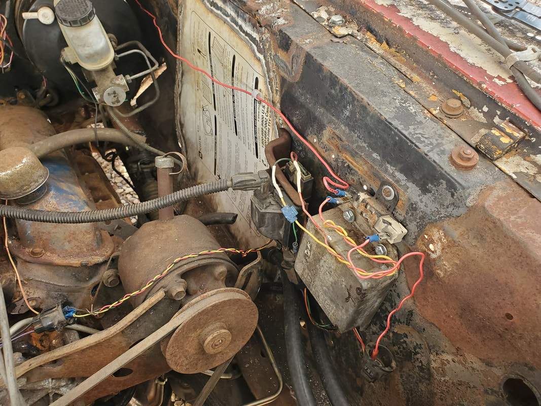
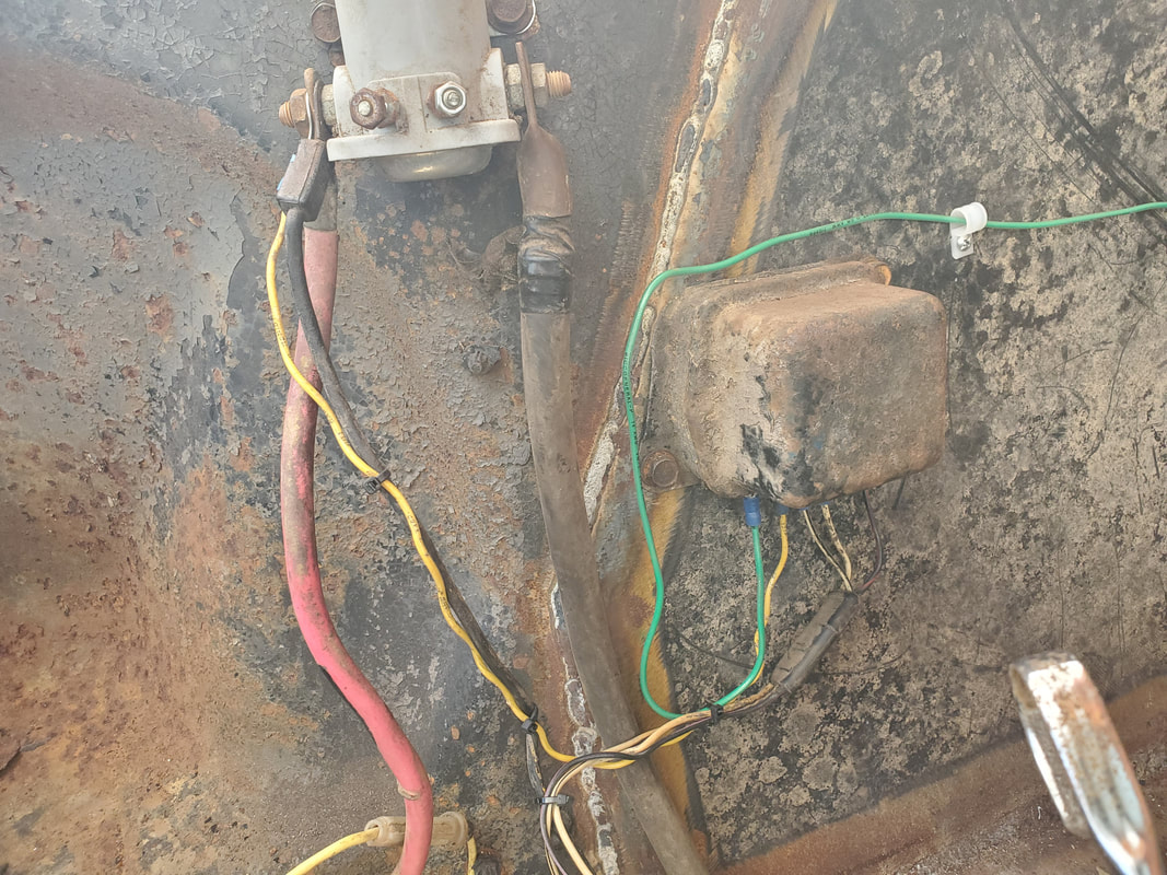
Duraspark ignition system wired up with ballast resistor mounted on top of module. Note the wire that is routed along the fender panel that supplies switched 12v power to the system.
With the ignition system wired up, I took care of some other small odds and ends, like getting the battery cables in place, getting the main power cable started that will bring power from the battery to the fuse box. I also ran a power line for the starter solenoid going into the dash and fuse box. As a result, I also had to get a universal ignition switch and headlight switch so I can wire in those components and get the electrical system even more completed. I still have to wire in the headlights and front turn signals. Right now, because I ran wires over to the points where the headlight and ignition switches go, I can get those mounted and fully established. 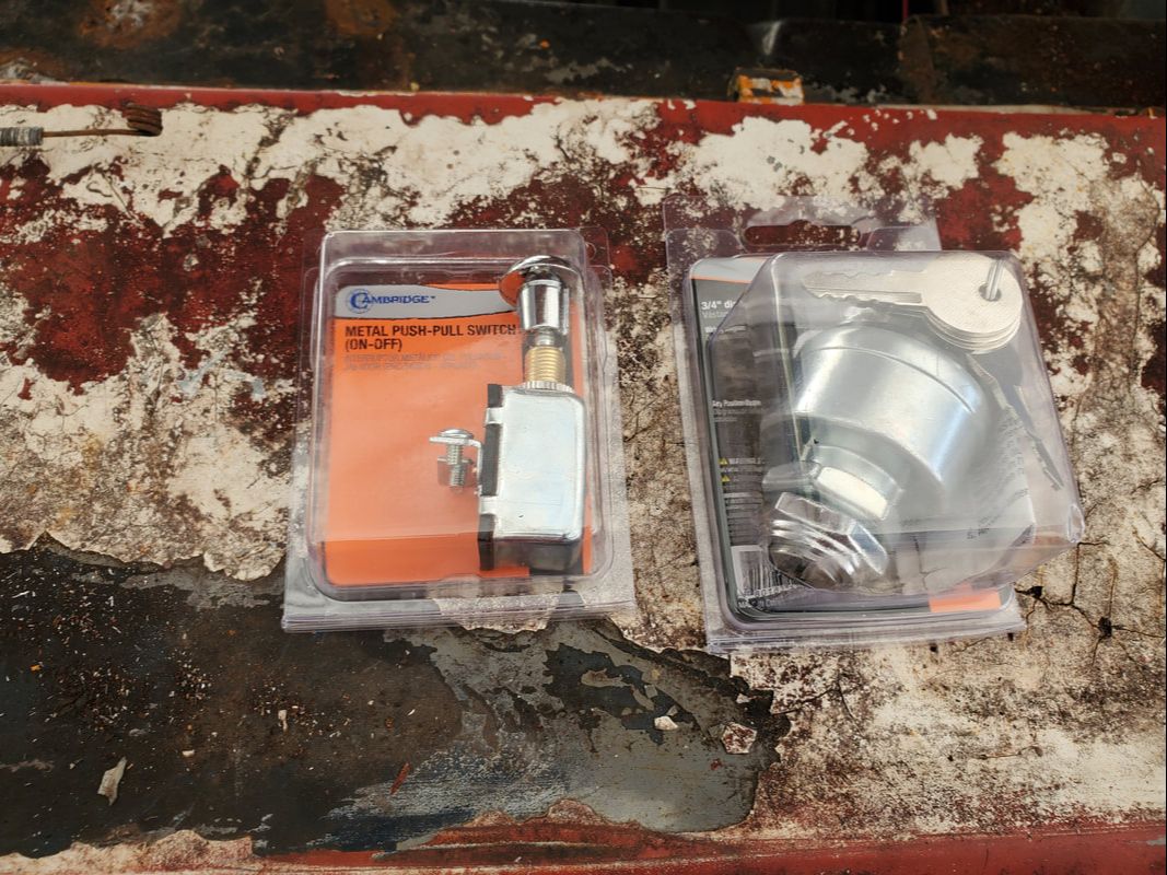
Universal ignition switch and headlight switch used in place of the stock hardware.
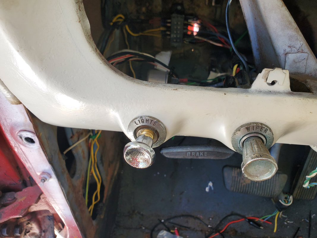
Headlight switch installed with modified bushing which contains the name of the switch. We're doing what we can to make things appear as stock as possible.
With the headlight switch wired up, I moved on to the ignition switch. Now, this switch was made to mimic a regular ignition switch in a car where it has four positions. Because of this, I had to change my original plan on how the fuse box would be wired up. I routed a wire from the battery cable over to the fuse box to feed raw power from the battery for the electrical system. With the ignition switch, I ended up taking the wire from the fuse box that was supposed to go to the switch for the starter solenoid and routed it to the battery terminal on the 4-way switch. The start terminal on the switch went to the solenoid wire going out through the firewall. From here, I connected a wire from the accessory terminal on the 4-way switch and ran it back to the fuse box, connecting it to the input terminals on the fuse box feeding the turn signal and line that'll feed the radio. There will be room for extra loads like an amplifier or CB radio (does anyone still use those?). The ignition terminal on the 4-way switch was routed via wire over to the fuse box to connect to the fuses for the Duraspark system, the wiper and HVAC blower and gauge cluster, which also feeds into the voltage regulator. The ignition terminal is only on when the key is in that position, as well as when the key is in the start position, a requirement for the distributor, which will need power during a start cycle as well as during regular running. Because of this feature in the switch, I can actually disconnect the extra hookup that I added to the ignition system to take into account the idea that I needed to have a separate line that would supply power to the ignition system from the start switch. Another thing I did to accommodate the switch was modify the bushing that was part of the original ignition switch that had the indicators on it. This piece would complete the assembly of the dash where the switch trim pieces would be kept in the original state, even with the universal switches. The same was done with the headlight switch where the trim bushing with the word "lights" is present even with the switch. Of course, cutting into the original piece would be considered a sacrilege to some, but so would installing generic pieces in an iconic car, so whatever. 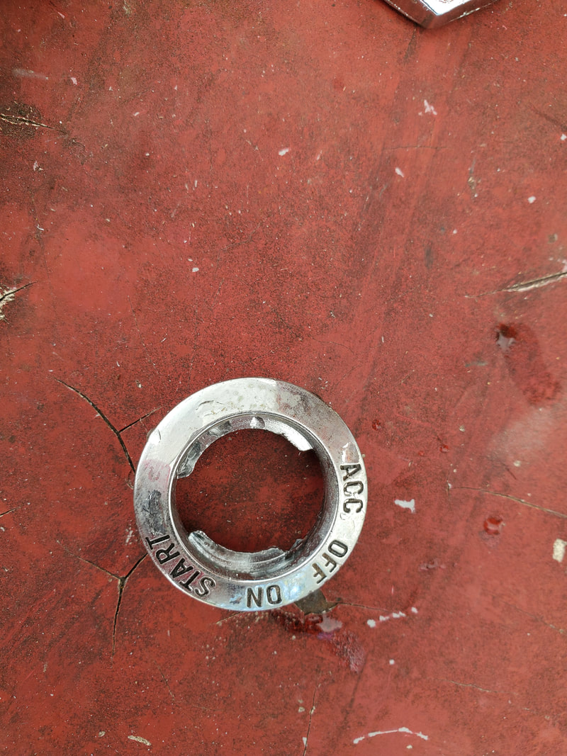
Bushing for ignition switch after whittling the piece out to accommodate the universal ignition switch to fit.
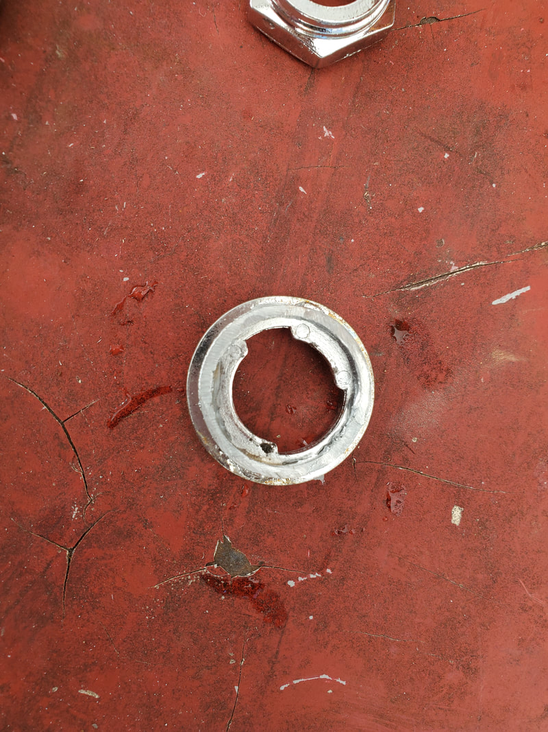
Back end/inside of bushing showing how the piece was ground down to open the inside up more.
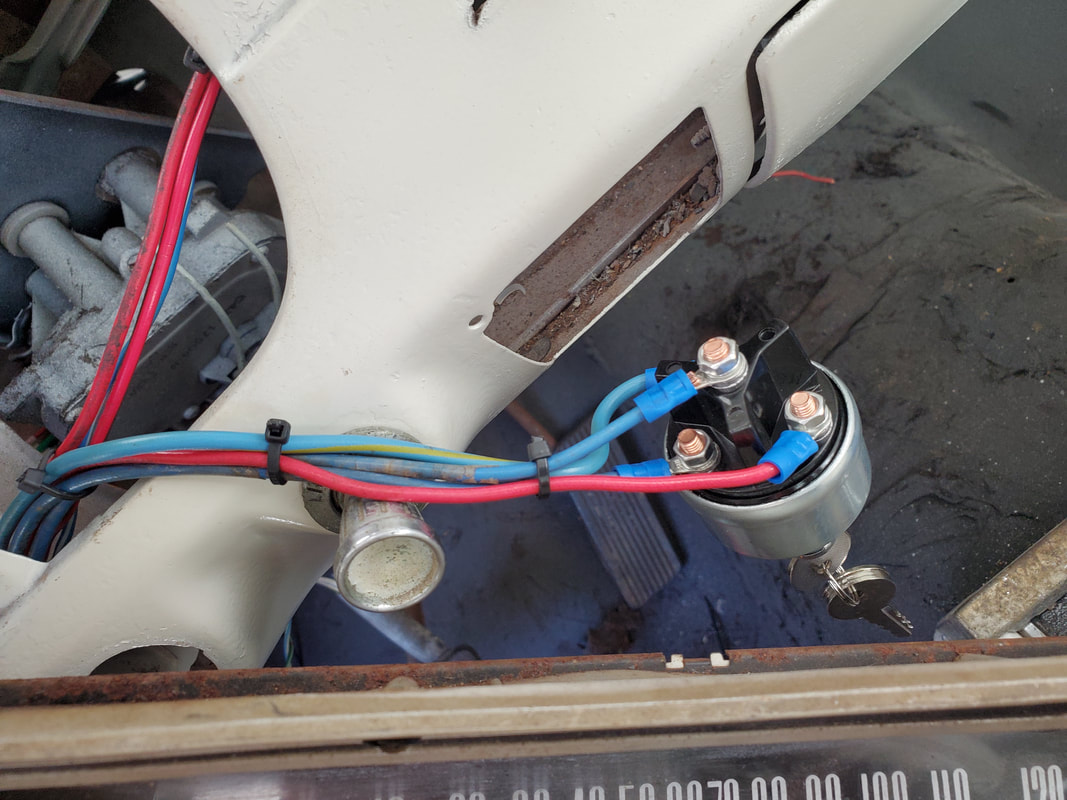
Ignition switch with wires connected and ready for complete installation
With the switch ready for installation and the loads mapped out on the fuse box, I can start to wrap up the electrical system on the car. I have on order an aftermarket turn signal assembly that clamps to most old car steering columns and has multiple wires for the front and rear lights as well as a switch for a hazard light, all of which is awesome. I'll have to look at how the assembly is made because if this switch is set up to mimic a standard switch assembly, it will possibly mean that it will switch between brake and turn signal lights on the rear just as well, meaning I can do away with the extra light socket and circuit that I ran to separate the two circuits. We'll see when the switch comes. I actually hope this is the case in order to clean up the wiring some.
With the rewiring kickstarted and a few components wired in under the dash, I moved to the rear of the car, with the intent of getting the lights wired up and the wire runs established in order to not have to keep the side panels and door jamb panels off too long. There would be several wires that have to run through the channel on the driver's side door. Because of the way the turn signal cam is situated, a long time ago when I tried to resurrect the flimsy multi-contact switch, I ended up adding a second light socket. There was only one socket in place with a two-filament bulb in each housing. The taillight would operate on its own but the other filament of each bulb is shared between the brake lights and turn signals, being switched between the circuits via the turn signal cam switch. I bypassed this by just adding another light socket to there would be three sets of filament to use instead of two. I'll definitely be keeping this layout, but in the meantime, I'd have to get wires established for all three circuits. I would have to hook up color coded wires for each socket so I can match up those specific colors to their respective switches in the car. I also wanted to add a circuit for the back up lights and of course the fuel sender when I do put a fuel tank in. Right now I was going to put an electric fuel pump in but I may check to see if the pump cam is still in place on the camshaft to see if I can drop a mechanical fuel pump back in place. Anyway, once all the wires were established, I zip tied everything together and used wire retention brackets to hold the wire bundle neatly in place along the rear of the trunk. The side panels and trim were also put back in place.
Wiring of the taillights established and zip tied together and routed over to an entry point in the rear seat panel on the driver's side.
Right side taillight wired up with wires routed along taillight panel to left taillight.
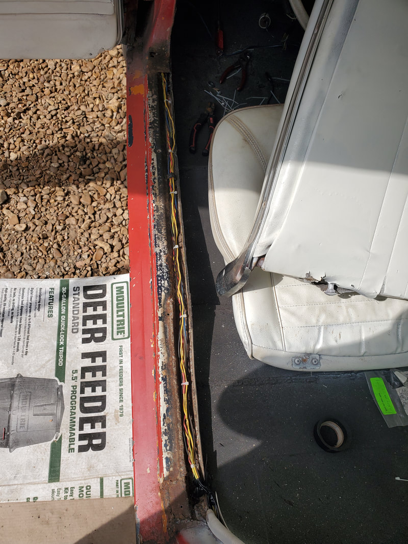
Bundle of wires routed through channel in door jamb from the rear.
With the wires for the rear all in place, I started getting those respective wires established where they can be hooked up to the fuse box. The taillight wires staged where the headlight switch would go. The brake light wire was routed and hooked up to the brake light switch, with the other side connected to the fuse box. The future back up light wire was staged where it will be further connected to and routed over to the shifter later. The turn signal light wires were routed up towards the gauge cluster and over the steering column because the next order of business would be to get the wires on the back of the gauge cluster hooked up and mapped out so they can be hooked up to their respective points in the wiring I had already established. 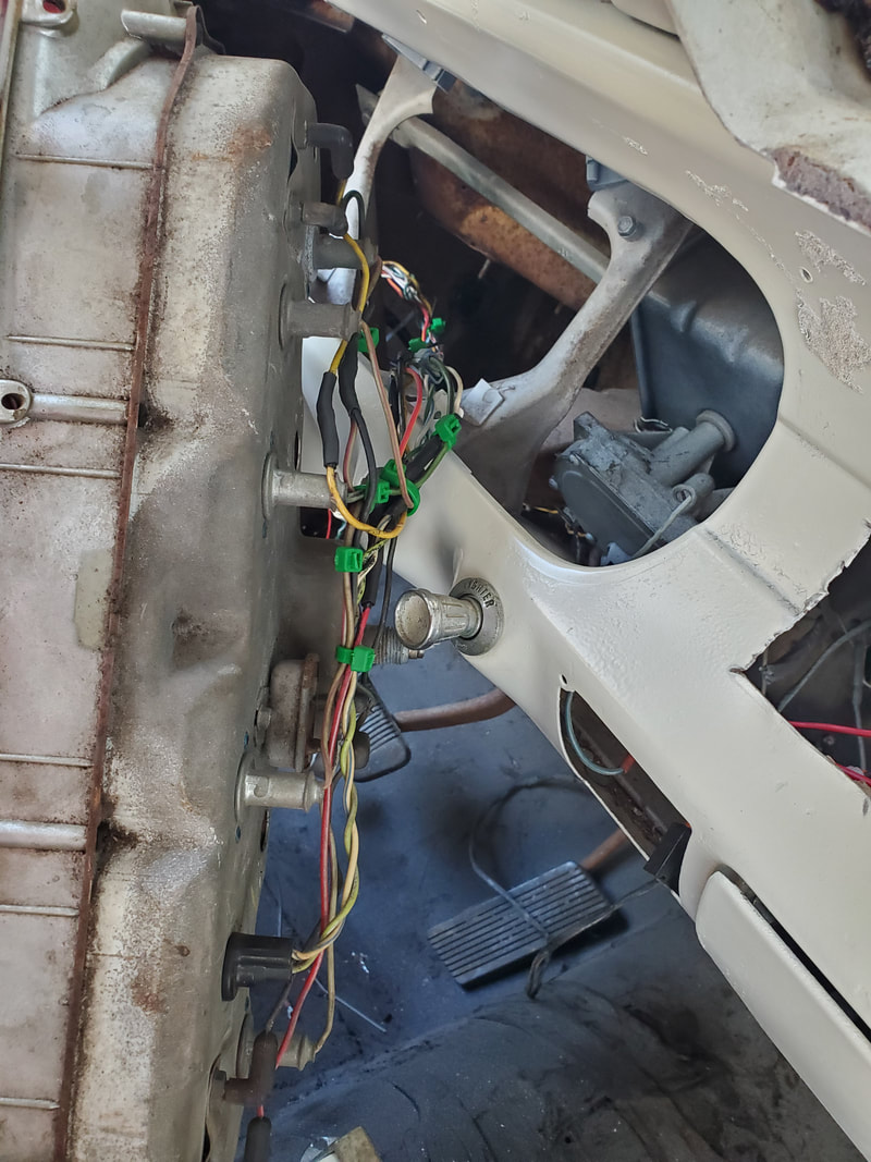
Back of gauge cluster with wires hooked up and bundled together with enough length to allow the gauge cluster to be pulled out without pulling out any wires.
The wires were hooked up among the gauge wires where they needed to go, like the temp and fuel gauges were hooked up to the on board voltage regulator then the input connected to a length of wire to be hooked to a switched 12v fuse. All the dash lights were hooked together with a shared output and added to with an extra length of wire to hook up with the taillight wire from the rear and further to the headlight switch when I do put one in. The wire for the high beam indicator was added to and staged to be hooked up later when I install a floor dimmer switch and the rest of the headlight circuit. The turn signal wires, which actually both route to a single indicator light to show that the turn signals are on, were hooked up with extra wire. With all these wires hooked and bundled together, I routed the wire bundle through the hole in the dash panel and staged the gauge cluster against the dash panel. I left enough wire to allow me to pull the gauge cluster out and not yank out any wires. When the gauge cluster is put back in place, the excess wires would be folded neatly to allow the gauge cluster to be seated in place. 
Gauge cluster staged against the dash with wire bundle hooked up.
With the gauge cluster wired up, there's not much else I can do under the dash until I grab some more components. I need a headlight switch, ignition/starter switch, even a SPDT switch to use for a makeshift turn signal on the steering column, the same way I rigged up the Elco and the Rustang, to do away with the flimsy turn signal cam. To complete the dash/gauge cluster hookup I'll have to establish the wires from the front of the car next. I have to get wire runs for the Duraspark system, starter solenoid, temp and oil senders, voltage regulator/alternator, and headlights/turn signals. I really don't want to mount the gauge cluster until I have the rest of the circuits wired up, as its actually easier to reach into the area when I have access through the dash opening.
|
