|
With my graveling being centered in the backyard area, getting a load down gets done a lot faster than normal. Instead of having to use the wheelbarrow to cart loads of gravel across a span of yard to a destination spot, all I have to do is just back the truck up to the edge of the gravel that has been already laid and just shovel right from the truck and onto the ground. As before, I'm continuing to lay a path approximately 12ft wide from the side path leading back to the fuel shed. Once I reach the fuel shed and the South fence, I can then cover some of the area around the fuel shed and the Southwest fence line, up to the old wood/pipe rack. From there I can lay a little gravel down around the edges of the auto parts and scrap area, after cleaning up some of the area. At that point I will start laying gravel down over the area just behind the garden fence where the tow dolly is currently parked then start laying a path due east. 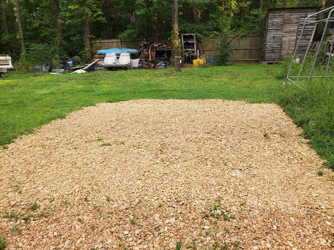 Gravel path, reaching out further from the side path and closer to the South fence. As I get more projects done and more crap cleaned up around the yard, I will be able to clear more ground that will allow me to lay gravel in spots that I missed or was otherwise unable to cover due to the coverage by foreign material. All of this will coincide with the construction of the interior fences around the garden, as well as the perimeter fences. Eventually I'll manage to get the compound set up the way I wanted to. Another thing we were surprised with today was more visitors. If you've been following the occurrences around here, you'll know that the visitors are typically of the animal variety, and as is the case here, that animal is typically avian in nature. In this case it was some more chicks. Yep, more baby chickens were hatched out by a broody hen. Acquisition of these baby birds was met with some resistance as the momma hen and patrolling roosters would attest to. 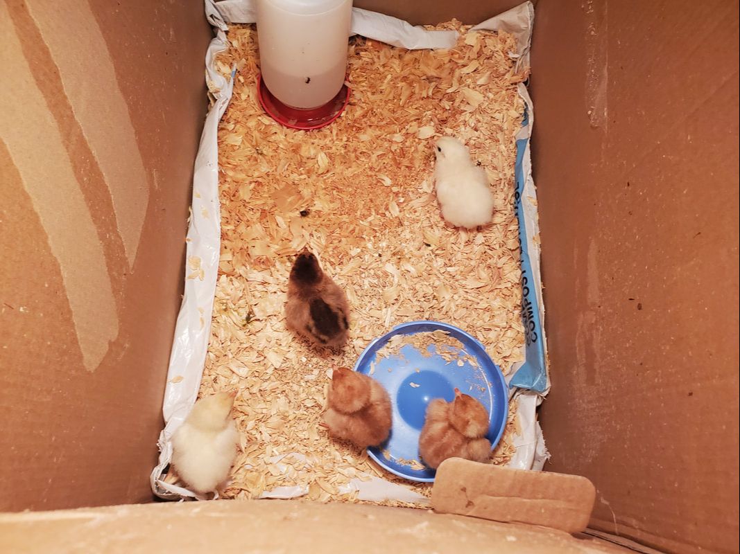 The five chicks that were discovered and are now put up in a makeshift brooder box to help grow them out large enough so they can be transferred to the Mustang Chicken Coupe's brooder section. After gathering the baby chickens and getting them set up, we discovered more eggs in the nest area, which happened to be the old doghouse that was supposed to be used by Old Dog during the cooler nights or when it was raining. We had an old blanket in the house for the dog but the hen that hatched these chickens hijacked this doghouse, pretty much evicting Old Dog for the foreseeable future. Once the smoke cleared, the hen went right back into the doghouse to sit on the batch of eggs within. There's around another six eggs in the nest, so who knows, we might end up with more baby chickens if these eggs are fertilized and viable. 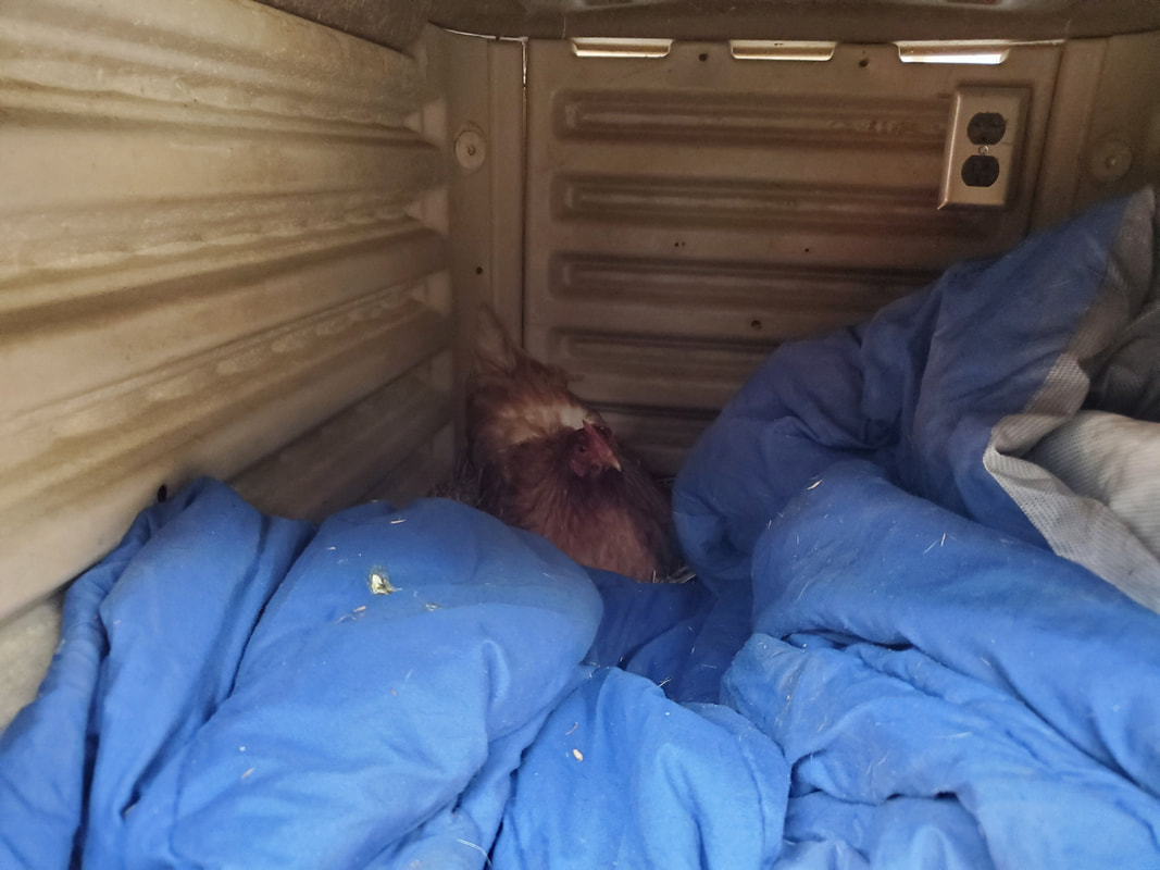 The momma hen, sitting on her nest, wishing someone would stick their hand in that doghouse. It is these occurrences that make having the chickens around worthwhile, as they end up providing eggs and in some cases, more chickens. This keeps us from having to buy more chicks as the current population is doing their job of further populating the compound with more birds. Of course I still want to add more ducks, even turkeys and some other oddballs, like guineas, to the flock. With the fitting out of the Minivan Chicken Coop, we will be plenty able to handle the load increase.
0 Comments
After addressing several other issues on the Scion, I finally got the opportunity to get under this car to address this problem. Because of the location of the hose, the best and safest way to address this problem was to put the car on ramps. I would have to slide well under this thing to access the hose ends and there's no way in hell I'd do this with the car on jacks. With the car on jacks I was plenty able to slide under the car with plenty of clearance. The relief was short lived as I had to look at a way to get a wrench on the bolt that holds the end of the hose to the power steering pump. The bolt was a 17mm wrench. While I could've used a socket, getting one in there where it would've stayed on and not destroyed my knuckle when the bolt did give way.
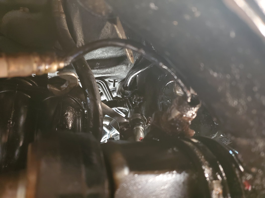
17mm wrench on the bolt holding the end of the power steering hose to the power steering pump.
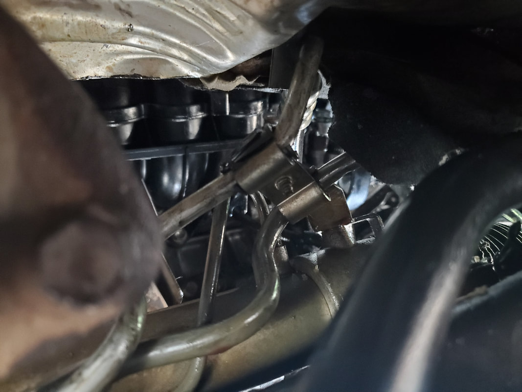
Once I got the bolt off I had to take care not to lose the double washer piece that seals the end of the hose. This hose is a high pressure hose and the end plus the washers are similar to many brake lines where they bolt to a caliper. I wanted to save the double washer since the new hose came with two single washers, which I did not want to tr and keep in place in those tight quarters while trying to put the new hose back in place. The next thing I had to address was a bracket that held the high and low side hoses stationary so they wouldn't move around during normal operation. This was a single 10mm bolt that once out, the bracket was separated and the hoses were free. 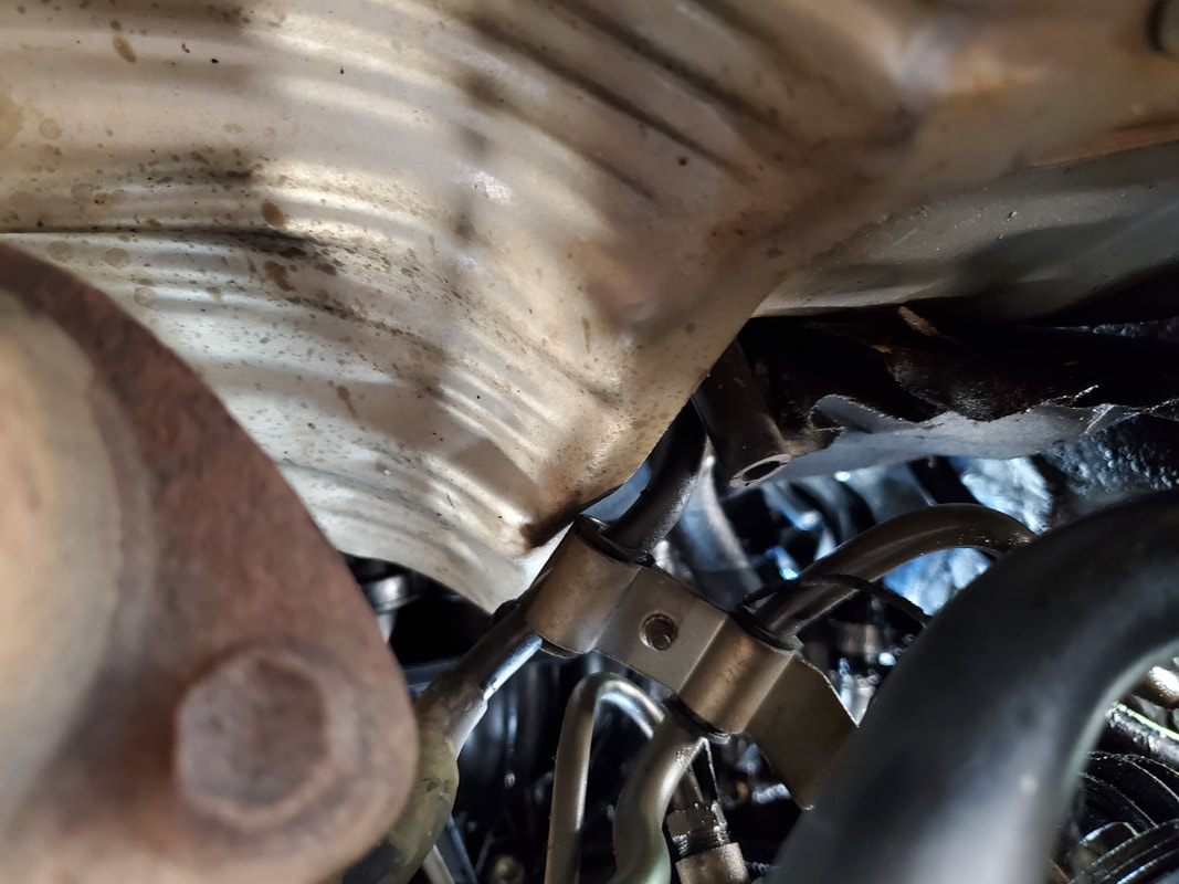
The bracket that holds the two hoses together and stationary during normal operation.
On the rack and pinion the two hoses are connected with compression nuts. Unfortunately the low pressure hose had to come off in order to remove the high pressure hose (the one we're replacing). These compression nuts are 17mm as well. I was able to access these from the left fender so it wasn't too bad. I didn't bust a knuckle getting these fittings loose. Once the hoses were loose, I was able to start removing our crappy hose. 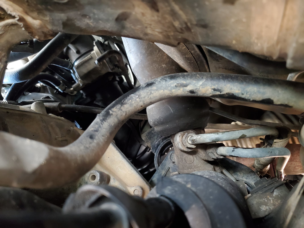
The two compression fittings for the high and low pressure hoses where they attach to the rack and pinion system.
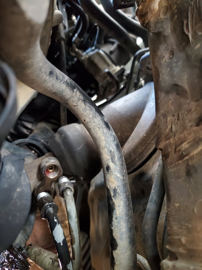
Both compression fittings disconnected from the rack and pinion system.
I had to take my time working the hose out, moving out the metal end that was plugged to the R&P more out from under the car while working the pump end of the hose out enough then pulling the middle portion out, working the rest of the hose completely out. With the hose completely out, I was able to get our new hose and start working on putting the new one back in, carefully working the ends in. I had to be careful so as to not damage the rubber portion of the hose. 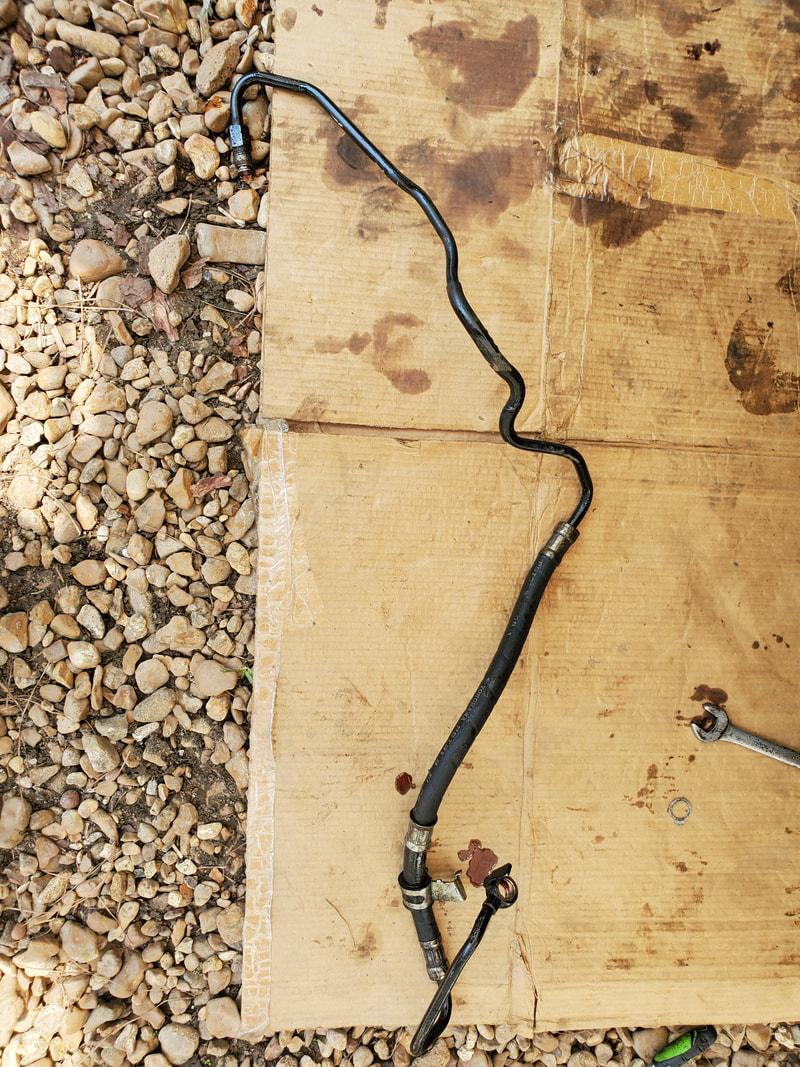
The old hose after removal from the car.
When I went to bolt the end back onto the power steering pump, I ended up having to remove the feed hose that connects to the oil reservoir. I should've removed this from the beginning, but I was trying to get away with not removing so much shit and that backfired. I was able to get the hose off no problem, another reason why it was stupid not to remove it from the beginning. Once I got that off I was better able to get the bolt lined up and put back in. Of course I ended up reusing the double washer, as stated before, because I wasn't about to try and keep the two single washers in place. With the power steering pump end of the hose secured, I moved on to the rack and pinion side. 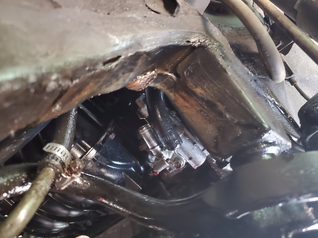
Reservoir hose disconnected in order to give me the space to be able to reinstall the bolt for the hose end.
I got the compression fittings back on and secured, but on our high pressure hose I had to orient the hose in a way where it was as close to the base of the bracket as possible. I had to bend the metal tube portion some to get it where it needed to be. Even after tightening the compression nut, I ended up having to loosen the bolt that holes the whole bracket assembly. This allowed me to turn the bracket assembly to be better able to get the new hose lined up enough to get it clamped in. I did have to take the old plastic bushing material from the old hose and use it on the new hose so when I put the bracket piece back on, it would hold the new hose tighter. Afterward I reattached the reservoir hose and tightened it up. I made one final check on all connections to make sure everything was tight. 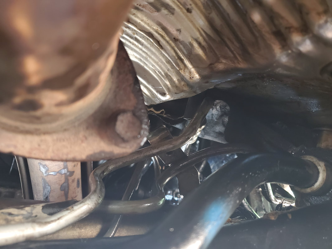
Trying to get the new hose lined up with the bracket base so I can secure everything.
Bracket bolted back together, with old plastic bushing on the new hose to hold it in place.
I filled the reservoir up and started the car. Of course, the system sucked down the oil that was initially put in the reservoir, requiring me to add another reservoir's worth of oil to get it topped off. I had to work the tires slightly side to side, since the car was on ramps, but that was enough to work the air out of the system as well as ensure that the system was completely full of oil. With that, I was able to back the car off the ramps and conclude this project on a good note. No leaks, system works as designed, I consider that a win!
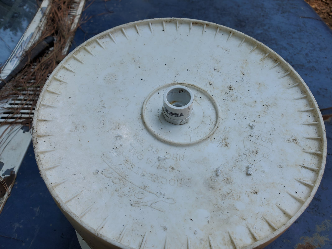
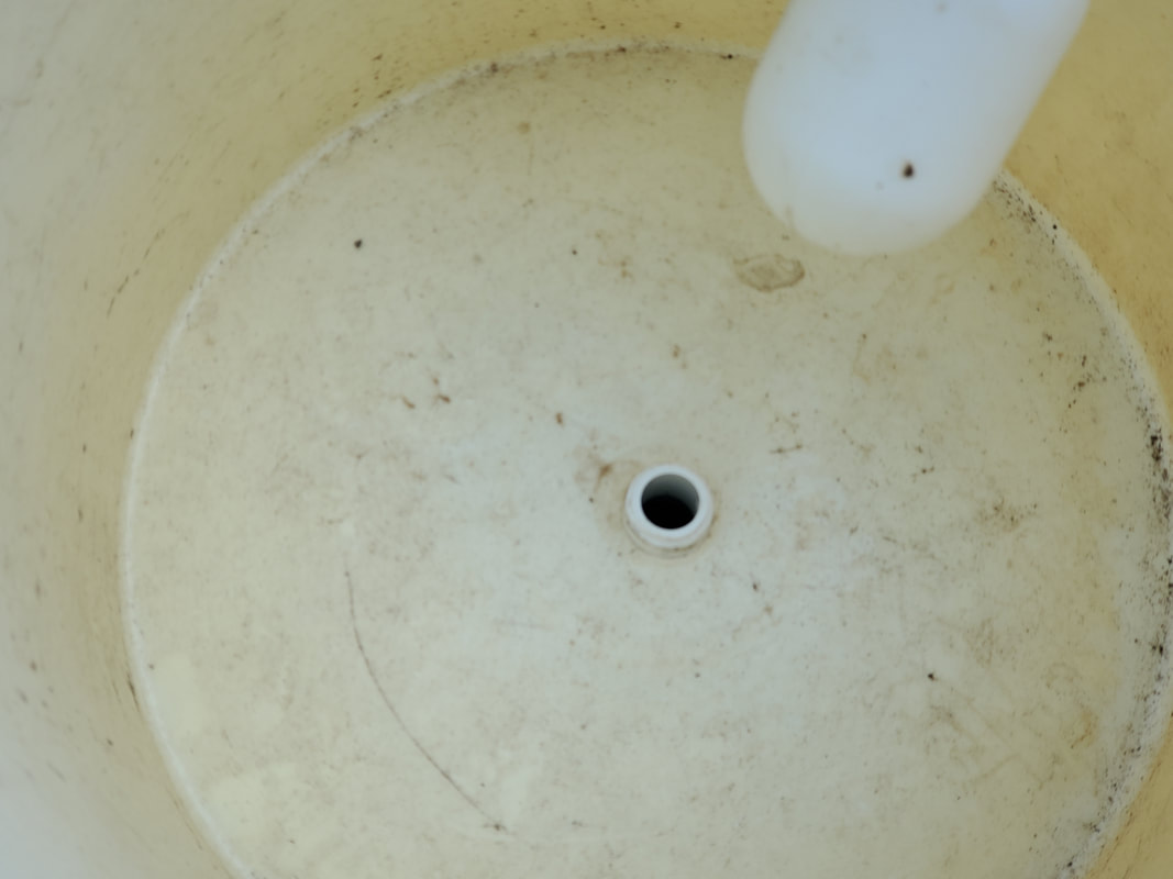
With the completion of the Version 2 of the watering apparatus in the Mustang Chicken Coupe, I feel amped up to get the Minivan Chicken Coop project underway. It isn't going to be that bad, its just really the installation of different hardware to make the coop a viable system. The first thing, while it was all fresh on my mind, was the setting up of the watering system. This of course will incorporate the bucket reservoir setup that is used on the other coops, a combination high pressure/low pressure system where high pressure water feeds into a regulator that feeds a float valve. The float valve fills the bucket which then gravity feeds the low pressure system that supplies the drinker cups. The first thing I have to do is build the platform for the bucket. 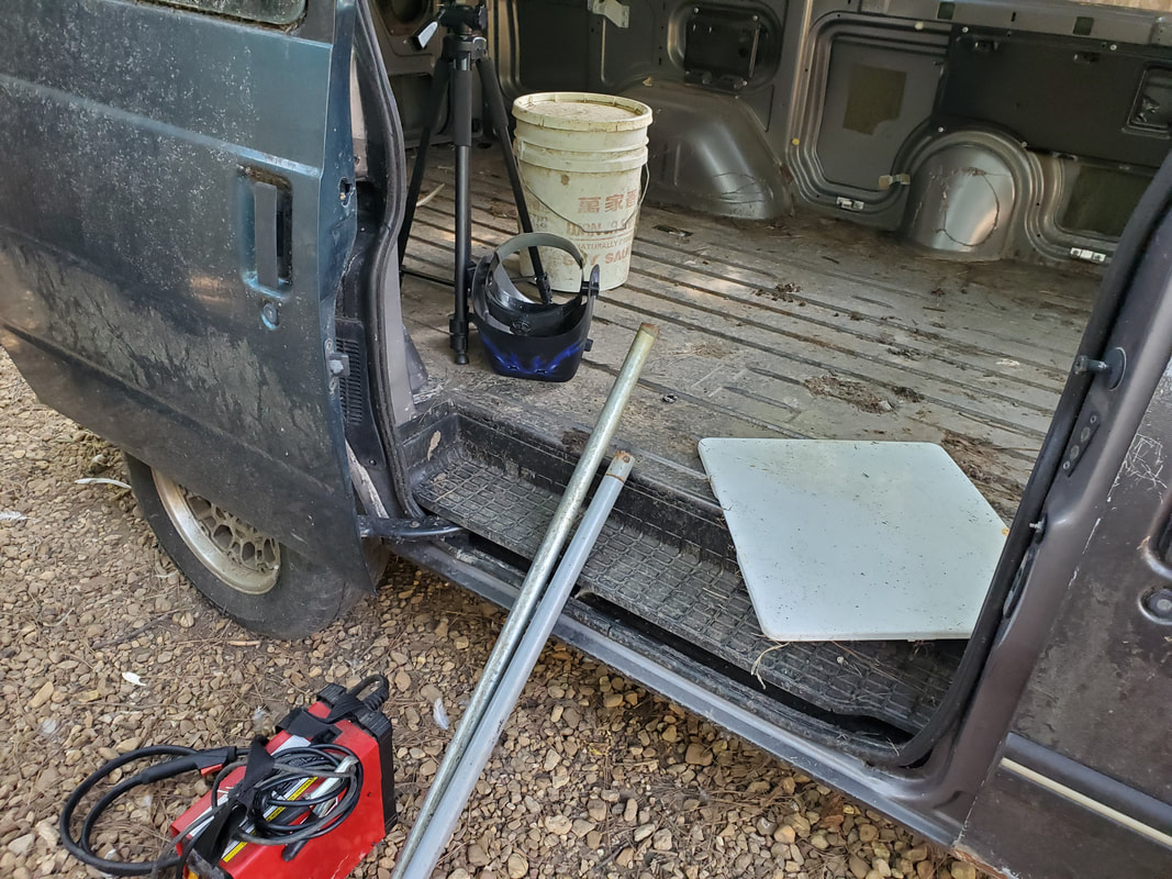 Scrap metal and tools all gathered up in preparation to build the watering system for the coop. The platform will incorporate a dryer door that will serve as a table, and a couple lengths of tubing that will serve as the legs. The other support side of the platform will be the fender hump. I had to weld the legs to one side of the dryer door then weld the other side to the body at the fender hump. The bottoms of the tubes were welded to the floor of the van, fully securing the platform in place. 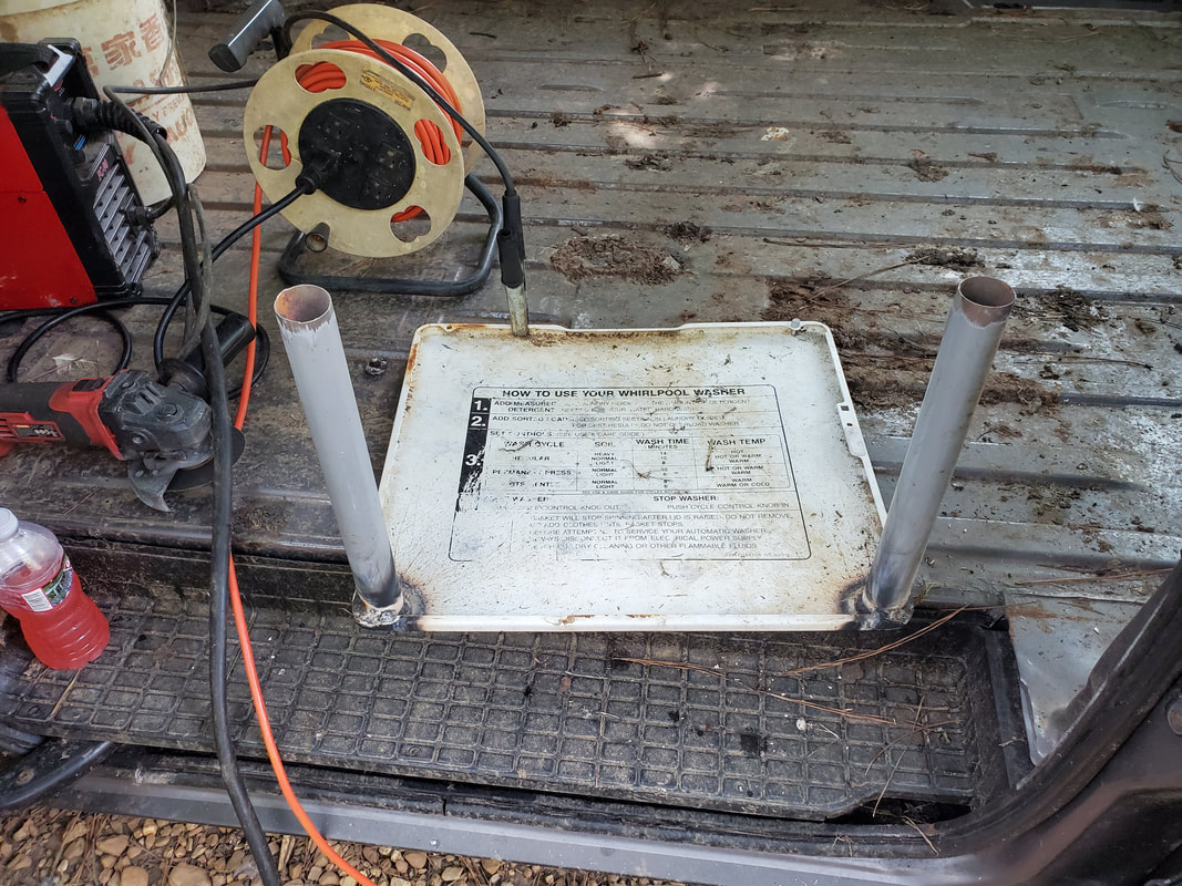 The dryer door with the two sections of tube welded in place. 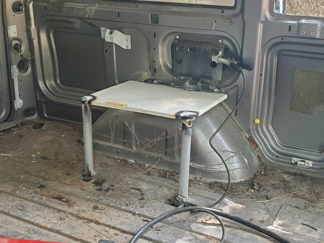 The scrap metal platform for the bucket reservoir and drinker cup manifold, all welded up. The next thing I did was attach a couple of angle braces to the sides of the legs. These angle braces will serve as anchor points for the drinker cup manifold. It will be zip tied to the angle braces at multiple points to hold everything steady. I did take time to assemble the manifold with the drinker cups, unfortunately coming up short by one drinker cup. One end of the manifold is capped off with a cap and the other side has a hose nipple. 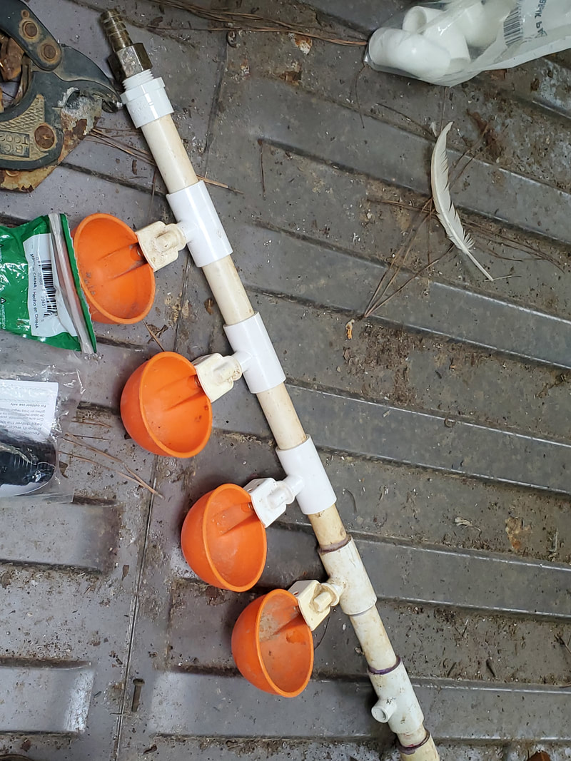 The drinker cup manifold assembled with the 1/2" x 1/8" tees and short pieces of 1/2" PVC. The manifold is capped on one end and has a hose nipple on the other end. The bucket reservoir already had a hose nipple fitting screwed in place, due to the idea that this bucket was used in a watering system on one of the chicken tractors in the past. I salvaged all this hardware, knowing it would be used again, and here we are. I situated the bucket in place and attached the hose to the nipple on the manifold, after zip tying the whole works to the angle braces. 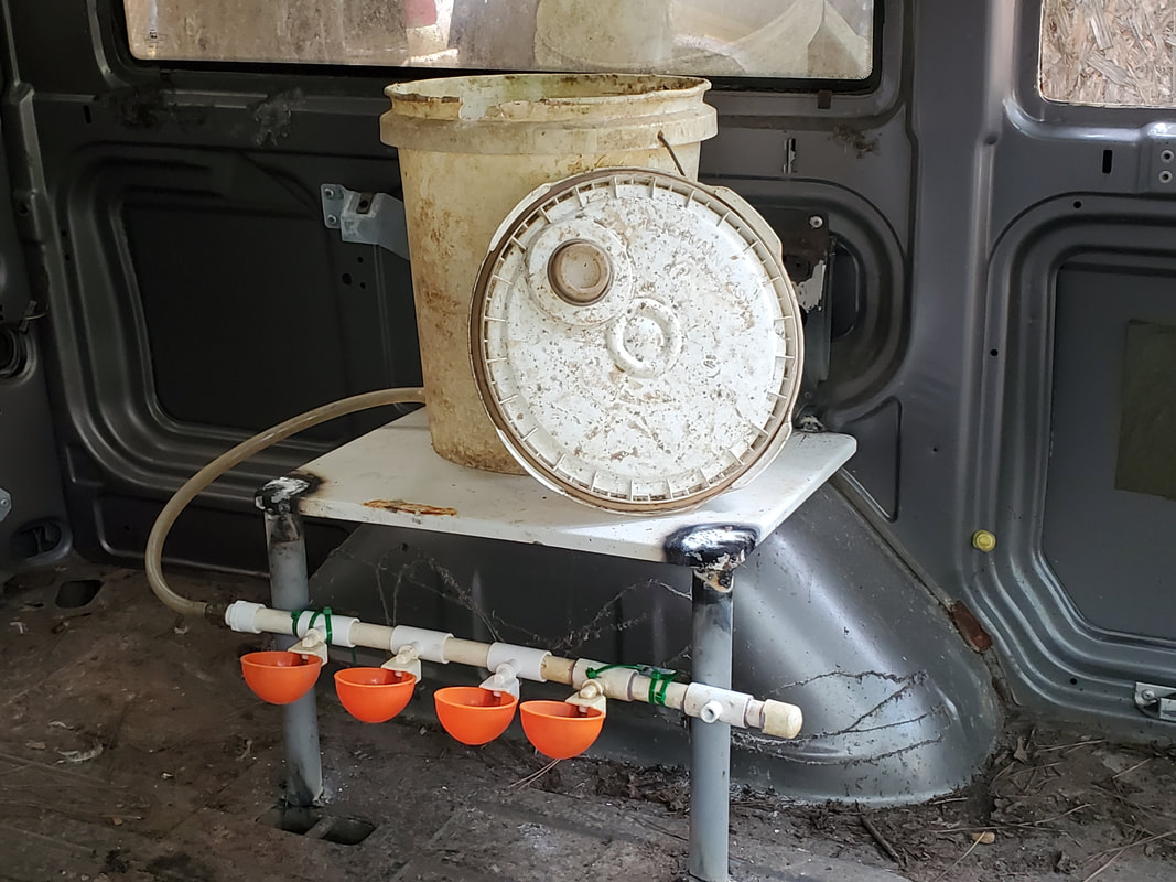 The platform, drinker cup manifold and bucket reservoir with connecting hose, all set up. The next thing I had to do was attach the float valve. This was as simple as drilling a hole to secure the float valve. Once that was done, I lined up the input hole on the float valve with the side of the van and drilled a hole through the side of the van. This hole allowed me to insert the 1/8" nipple through the outside of the van and into the thread on the float valve. Doing this effectively locked the bucket reservoir in place. On the outside I attached the adapter fittings and regulator, pretty much completing the MCC's watering system. 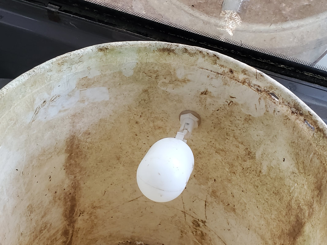 The float valve secured in place on the bucket reservoir. 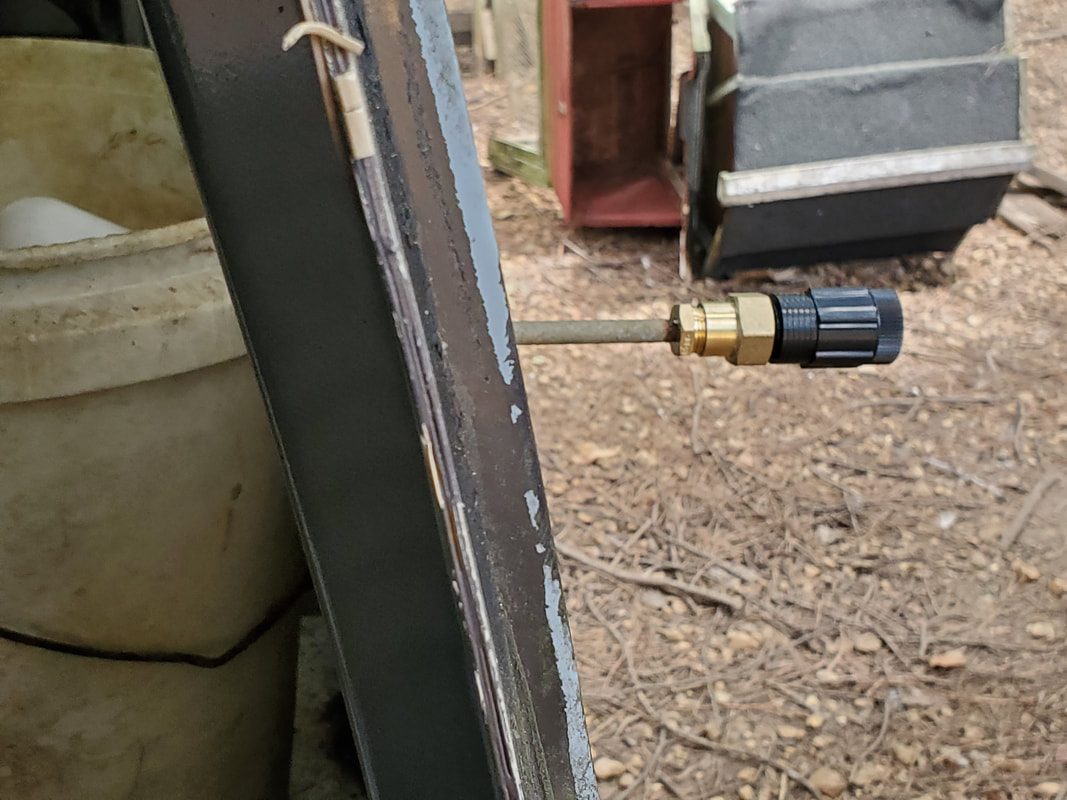 A shot through the open window showing the bucket reservoir and the 1/8" nipple with adapters and regulator as it passes through the side of the van body. All I have to do to make the watering system active is get a hose to the regulator and turn the water on. Of course it's not that simple, I'll be digging a shallow trench, like I did with the other car coops, to route a short run of hose over to the MCC, then routing the remaining hose up to the regulator. I might anchor some kind of pipe or tube in the ground with which to zip tie the hose to so its not pulling down on the regulator and 1/8" nipple. Other than that, the MCC's watering system is complete. The next order of business before I do that other outside stuff mentioned is to build a platform to hold the larger bulk chicken feeder in place.
When I left off with the water system upgrade on the Mustang Chicken Coupe, I finished up the low pressure side of the system, with the bucket reservoir and the output line connecting to the coop's old plumbing. I had to get some fresh PVC glue since this trash has a very short life span and the glue I had was nothing but solid plastic. I did take a moment to cut the sections of pipe for the high pressure water line so all I had to do was glue them together once the glue was in hand.
Bucket reservoir filling up with water after activating everything once the high pressure line was glued together.
With everything glued together, including the regulator, I hooked up the hose and turned the water on. The float valve started slowly filling up. Once the water levels were up high enough in the bucket, water started flowing to the drinker cups. I had to clean out some old dirt in the main cab drinkers. As water continued to fill the bucket, the drinker cups filled faster. 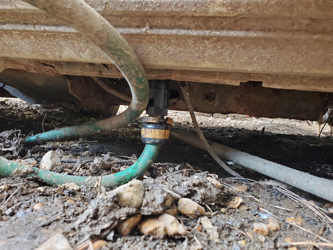
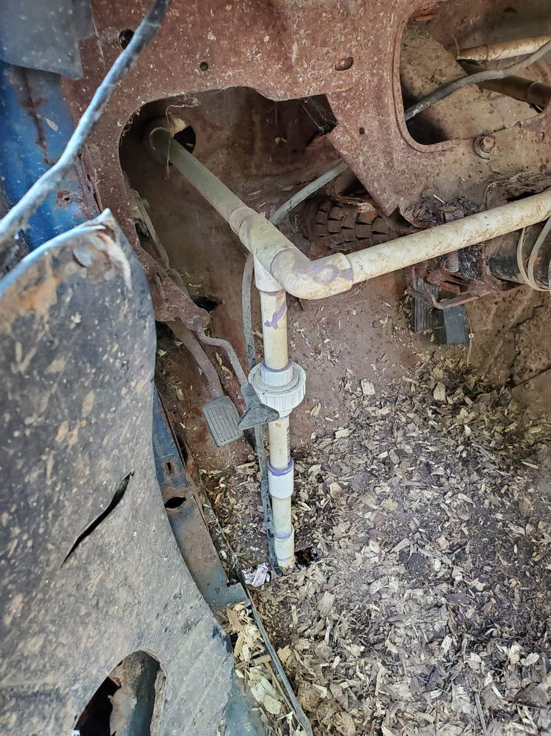
The 25psi regulator on the end of the high pressure line going into the car, with the hose hooked up.
The drinker cups in the brooder section were already filled up as well since the main water lines are at the same level. I had to make some adjustments to the float valve so it would shut off before the water level got above the float valve itself in order to minimize leakage. As is always the case, there's going to be some leakage with this cheap shit, but with the lower pressure due to the regulator, leakage is minimized, for the most part. 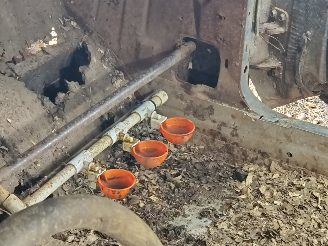
Drinker cups in the main cab area filled up with water, ready for some drinking action by the bigger birds.
With the drinker cups now online in the Mustang Chicken Coupe, I can remove the watering bottles from the brooder as well as start making my final plans for the fitting out of the Minivan Chicken Coop. As is the case with the other car coops, the MCC will use the same watering apparatus, propped up on a pedestal to hold the bucket. Having these car coops fully set up with automatic watering apparatus also makes it more sustainable for the multiple birds we have, as well as future acquisitions since we continue to plan on growing the flock. 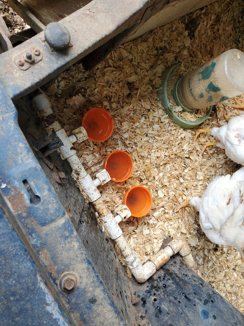
Brooder area drinker cups filled up, with baby birds already flocking around them for a drink.
If the chickens continue to do what chickens do, we may very well end up with more baby birds hatched out by broody hens, which will then push us to have to use the Mustang Chicken Coupe's brooder area more often, prompting us to better finish out the setup with updated ventilation and heating apparatus. I've seen coil heaters made to screw into standard light sockets that would be better than the large infrared bulbs we typically use in brooder boxes. Also, in the chicken yard I have plans to dismantle one of the old chicken tractors and even the old firewood shed chicken coop to make room for a storage shed to house all the stuff used for the chicken coops and brooders, feed, etc. Keeping everything in this one central location will go a long way to neatening up the yards within the compound.
After a couple years in action, the watering system on the Mustang Chicken Coupe has revealed itself to be a flawed design. The biggest problem lies with the water pressure going to the drinker cups. These drinker cups were designed to be used with an extremely low pressure, such as that would come from a gravity feed bucket system. The Toyota Chicken Truck and the S10 Ranger Chicken Coupe both utilize the updated version of the watering system that will be incorporated on the Mustang Chicken Coupe. This setup uses a bucket with a float valve, fed from the water line through a 25 psi pressure regulator, which then gravity feeds from an output down to the drinker cups. The float valve is better able to take the higher pressure compared to the drinker cups, which time and again proved themselves unable to hold up.
The old water line as it feeds up through the floor with only a union to disconnect the line to allow for the removal of the garden hose connected to the input.
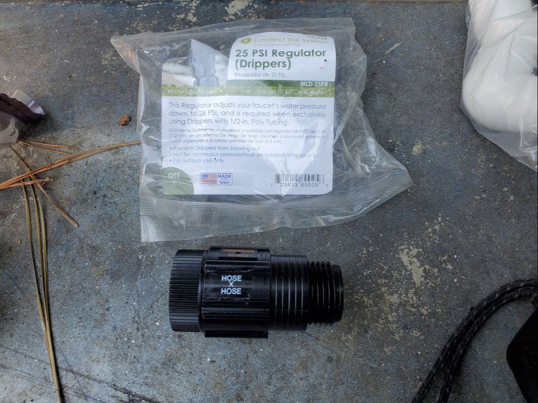
The 25psi garden hose thread regulator to be used on the input side to feed regulated water pressure to the float valve.
One of the first things I had to do was cut the water line where it feeds into the car, through the driver's side floor. I left enough 1/2" PVC exposed from the elbow to connect to with the new apparatus. Fittings will adapt the 1/2" PVC to the male thread garden hose regulator, which in turn accepts the male end of a regular garden hose. Once that was done, I moved over to getting the bucket tank/reservoir set up. Since the PVC glue I had dried up, I decided to work on the low-pressure side of the system first. This involved adding another conduit pipe alongside the pipe that is currently used as a roosting post. A couple conduit brackets and screws secured this piece of conduit in place so I have somewhere to set the bucket upon. 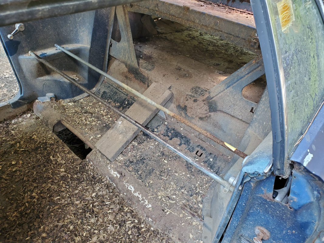
The extra conduit added alongside the first pipe, allowing both pipes to be used as roosting posts and support for the water reservoir.
On the bucket, I had to drill a hole to secure the float valve in place. Once that was done, I drilled another hole in the bottom of the bucket, where I screwed a 1/2" male thread to female slip adapter. Teflon tape helped seal the threads. From here I added some small pieces of pipe, used a 90-degree conduit elbow and some more standard elbows and lengths of pipe. The low-pressure output line going from the bucket to the old water system runs across the driver's door opening, about a foot off the floor, to connect to the old system. Since this is low pressure, no glue is needed here. 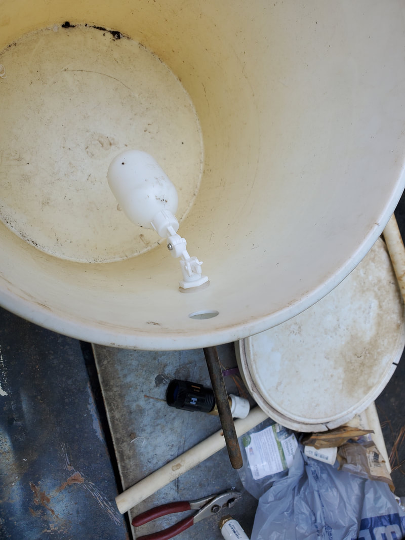
The float valve installed in the hole drilled in the side of the bucket using a step bit.
Adapter screwed into hole in bottom of bucket, also drilled with step bit.
A shot from the inside bucket of the fitting screwed in place.
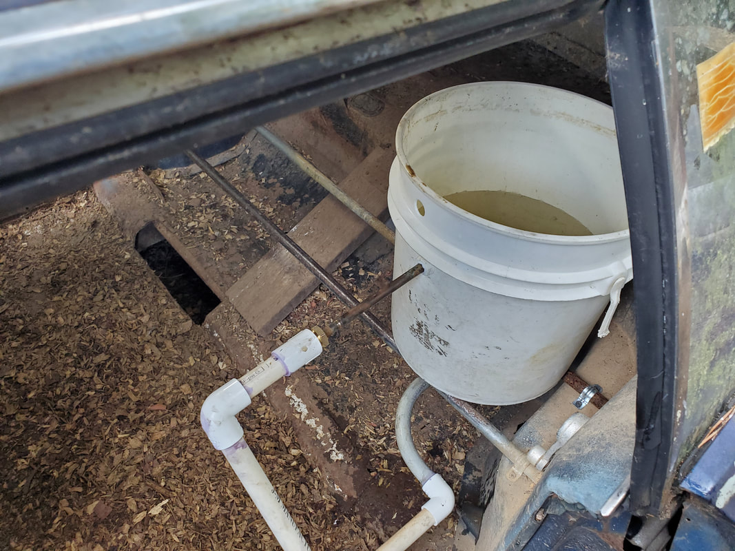
The bucket was situated on the two conduits with the PVC pipes connected. Next I cut the lengths of pipe that would be used for the high pressure side of the water system, going through the floor to where the regulator will be connected to it. Even though I still need to glue all this pipe together, I ran everything to run parallel to the low pressure lines, so once everything is glued together, I can secure the two lengths of pipe to one another for rigidity. The driver's door was never intended to be opened anyway so once everything is online, the door will be shut and kept shut, only opening for cleaning of the coop. 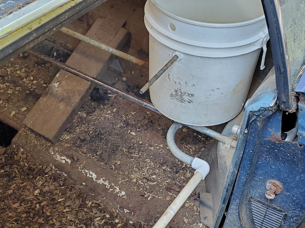
The bucket reservoir situated on top of the pair of conduits with the PVC pipes connected to the adapter. The brass pipe coming from the float valve will be connected to the water line going back to the garden hose and regulator, making up the high pressure side of the system.
The low pressure water line as its routed from the bucket reservoir to the end on the old water line, connected to it to complete the low side.
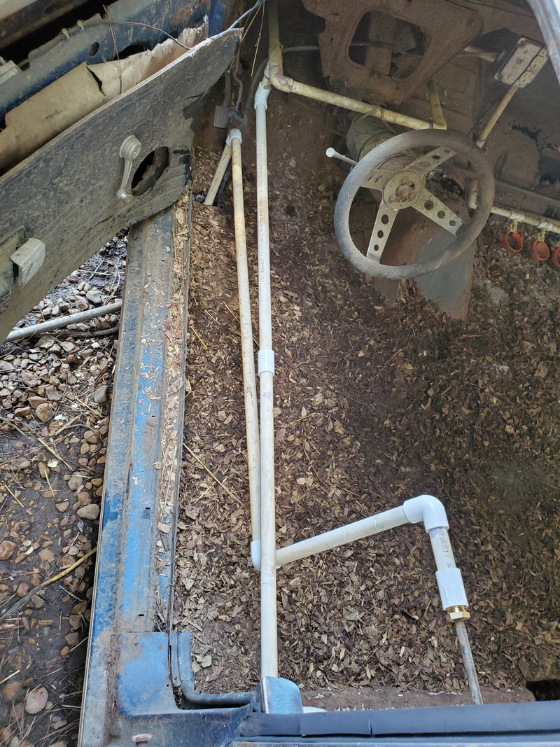
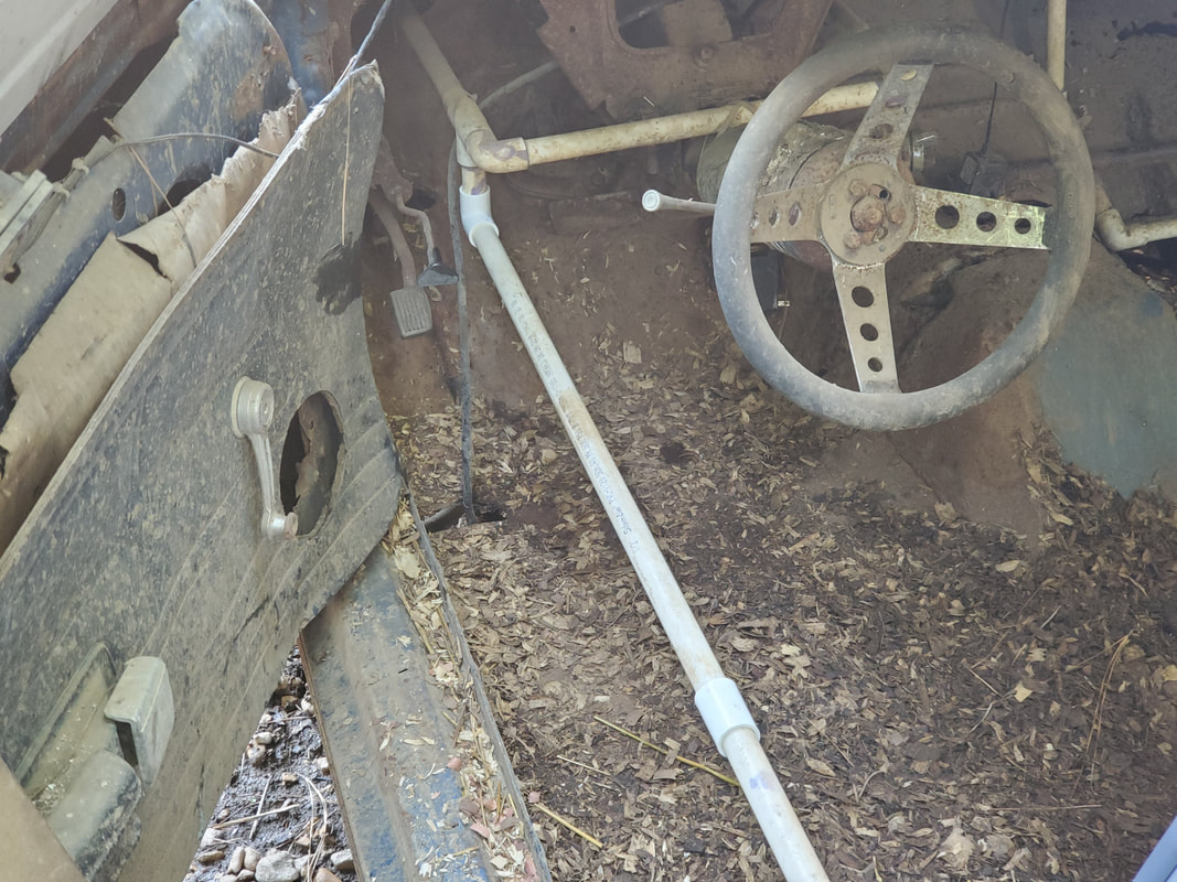
The two water lines, high and low pressure sides, routed along the driver's side door opening and rocker panel to the front where they're routed to their respective points.
With the Mustang Chicken Coupe's watering system updated, I can move forward with the construction of the Minivan Chicken Coop, post haste, in order to get the whole thing online alongside the other car coops, and work on dismantling one of the old commercially made chicken tractors. The structure is very weak and falling apart and has already been stripped down due to rot already. It's time for this thing to be retired to help clean up the chicken yard. The other chicken tractor doesn't have much longer to go before it too degrades enough to warrant dismantling and disposal. Once this happens all that will be in the yard are car coops and the old firewood shed turned coop, which too, will most likely be dismantled.
With the completion of the first bulk chicken feeder, I gathered more hardware in order to do the next and much bigger unit, the one that I decided to actually use for the minivan chicken coop. This setup is about the same as the first one in what it uses. Instead of the metal RV chimney shield of the first feeder, this one uses the plastic portion of the shield that waterproofs the roof around the chimney. My plan is to use the plastic shield as the connector between the hopper and the chicken feeder, which is another gallon size bulk feeder. The hopper is an old bulk dog food feeder that's missing some things to make it a useable feeder.
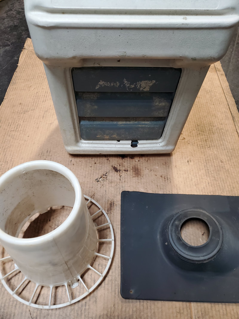
The three main parts to be joined together to create the bulk feeder: An old bulk dog feeder, an RV chimney roof shield, and a gallon bulk chicken feeder body.
The first step was to cut down the plastic shield to the dimensions of the bottom of the bulk hopper. Once this was done, I then traced a line around the inside of the shield to make another oval shaped hole, which was then cut out as well. 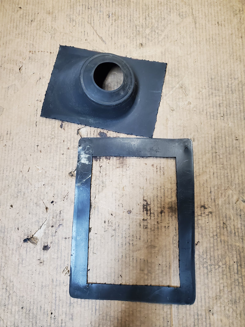
Trimming the excess material from the chimney shield in order to make the piece fit on the bottom of the dog food feeder.
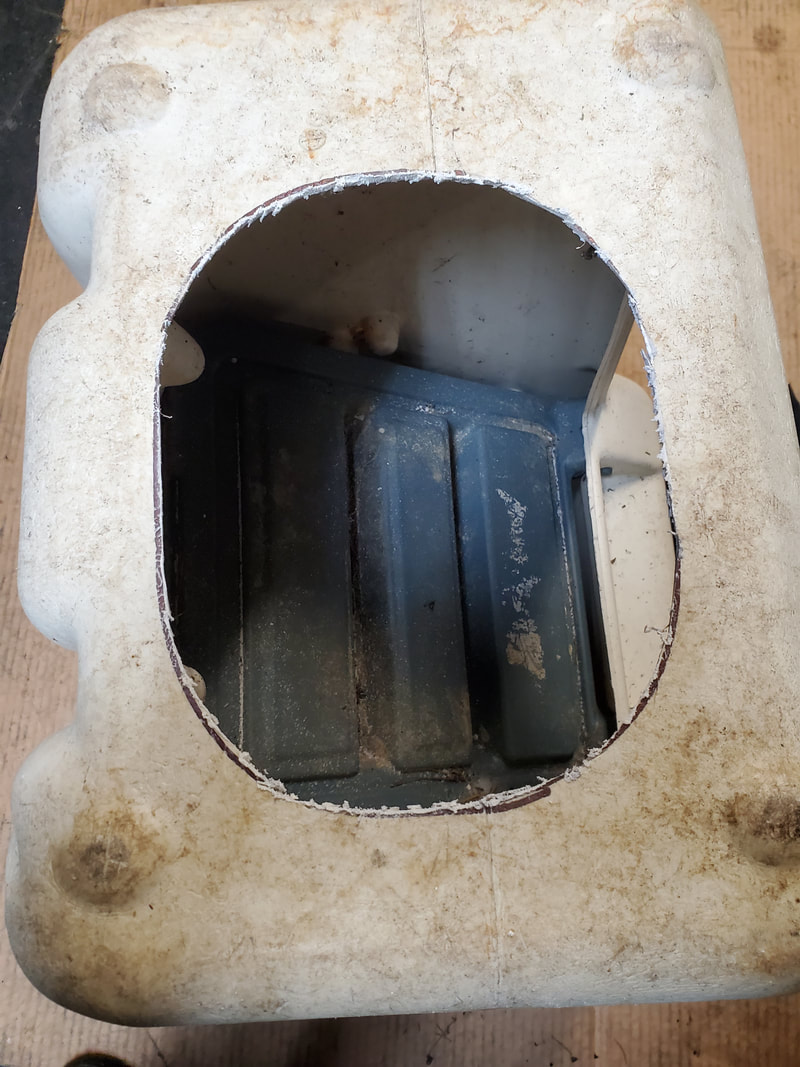
The hole cut out of the bottom of the dog food feeder, matched up to the chimney shield.
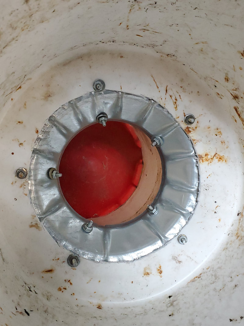
I then drilled six holes around the corners and the middle of the shield, using small nuts, bolts, and washers to secure the shield to the bottom of the dog feeder, covering the hole. Quick and easy. The next move was to seat the hopper of the chicken feeder on the mouth of the shield and drill five holes diagonally, same way as I did with the first bulk feeder. Extra long bolts with nuts and washers were used to secure the hopper to the shield. 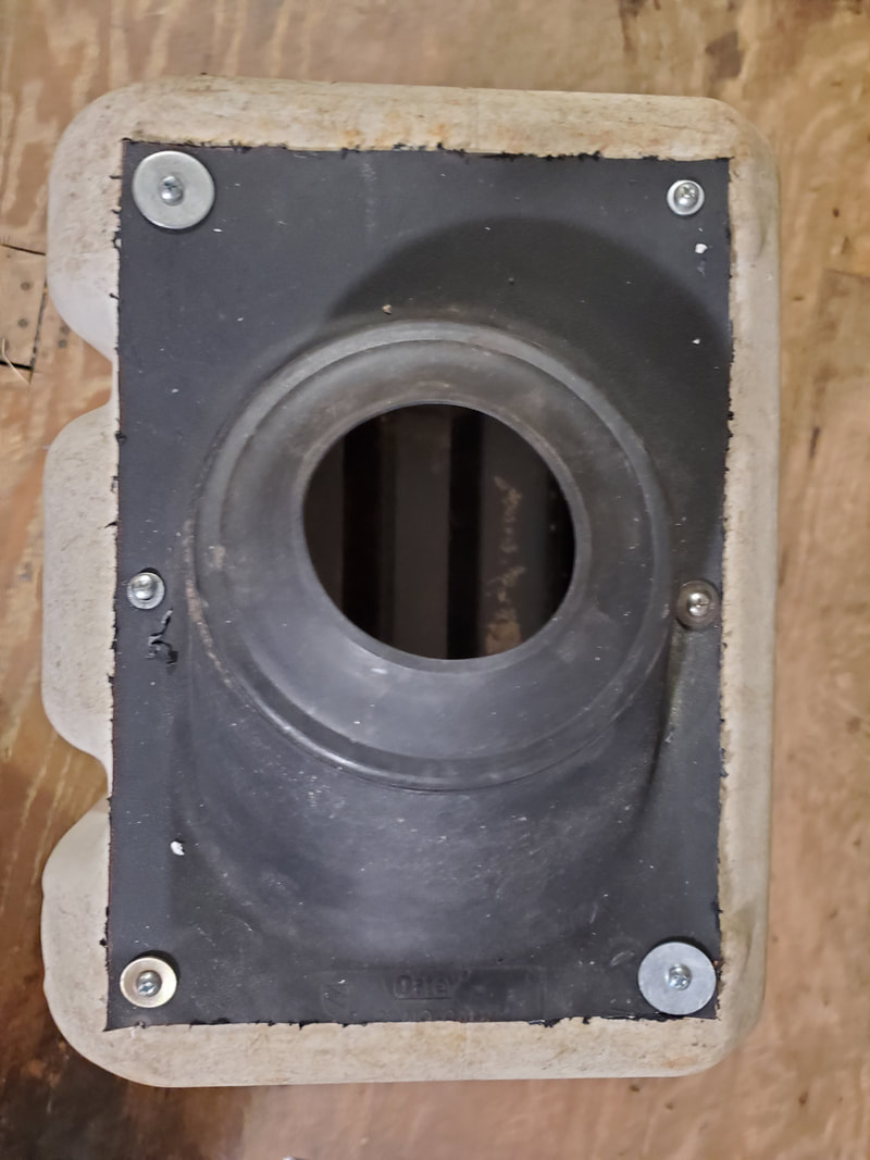
Securing the chimney shield to the bottom of the dog food feeder using nuts and bolts.
Securing the chicken feeder body to the chimney shield using long bolts.
Unlike the first bulk feeder, I didn't bother to use any hot glue to seal any gaps as they weren't significant to warrant sealing. The flap door on the dog food feeder is held down by simple gravity and didn't need to be locked in place. Besides, its ability to open can be useful. When the feed is depleted, I can open the flap to brush out the remaining old feed into the chicken feeder portion of the hopper so it doesn't sit in the spots around the hole where it can eventually go bad. The top also has a lid to cover the unit up to keep things sealed just as well. 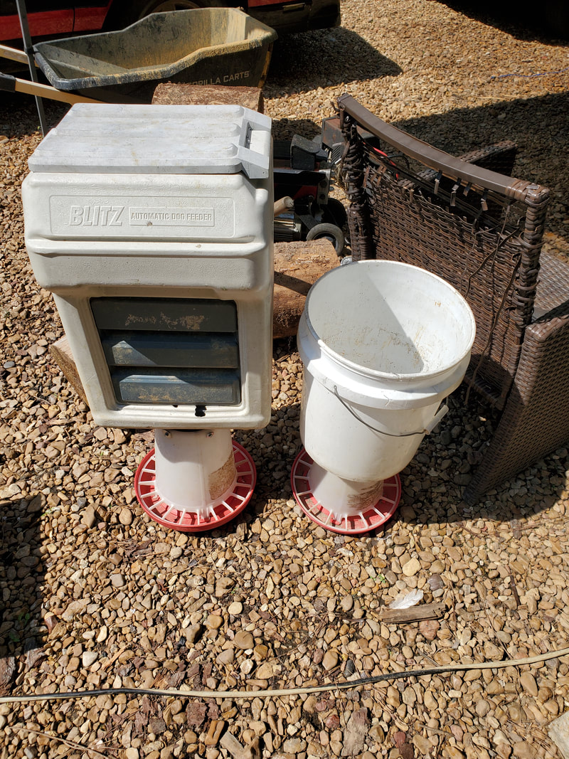
The two bulk feeders, the larger one will be used in the Minivan Chicken Coop and the other will be used in one of the other car coops.
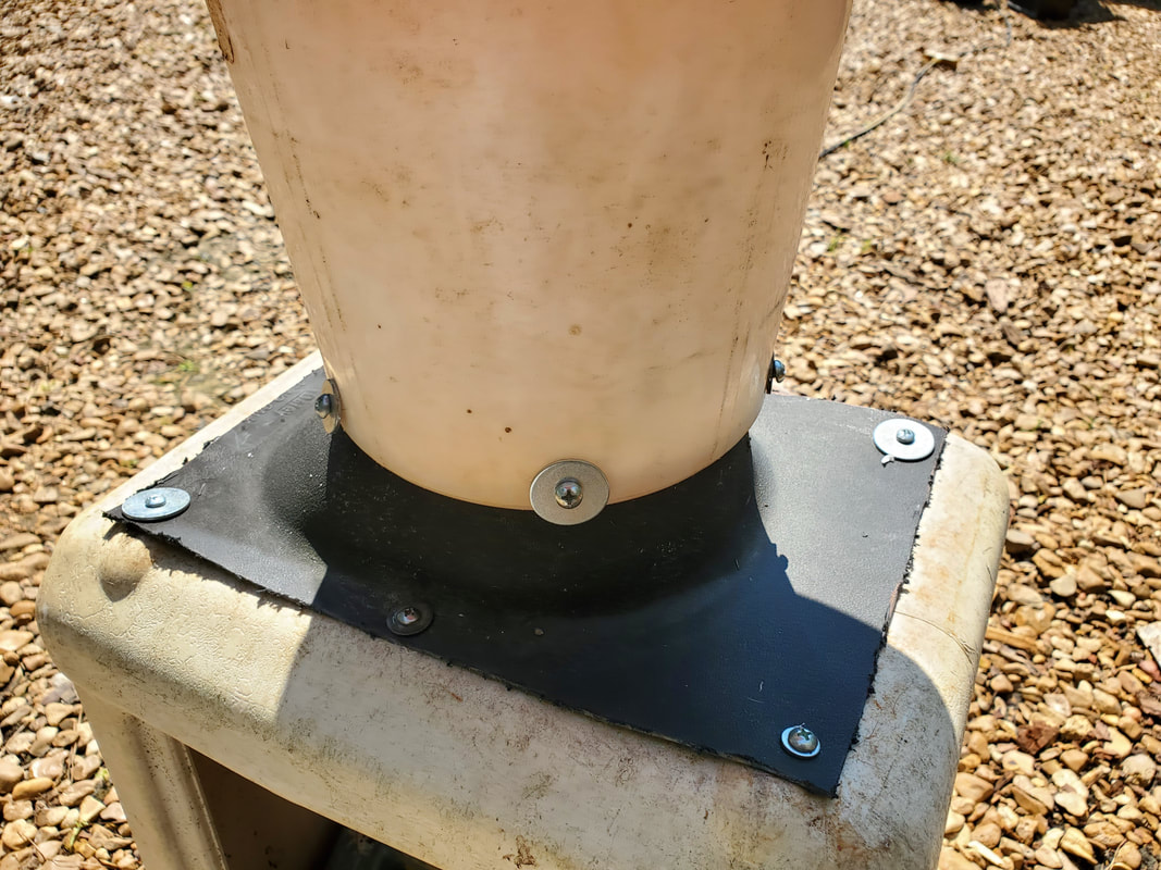
Just like the first bulk feeder, because of its style of construction, I'll have to make some form of table or support that will cradle the hopper portion to hold its weight in feed while allowing the chicken feeder part of the device sit touching the floor of the coop. This won't be a big deal as I have plenty of material to make something of this nature. Because of the disproportionate size differences, I'll probably use the smaller unit in one of the other coops and most likely supplement this larger feeder with a large commercially made unit to get double the feeding ability when needed. With that, the next move will be to actually start building out the Minivan Chicken Coop, once I gather a few more pieces.
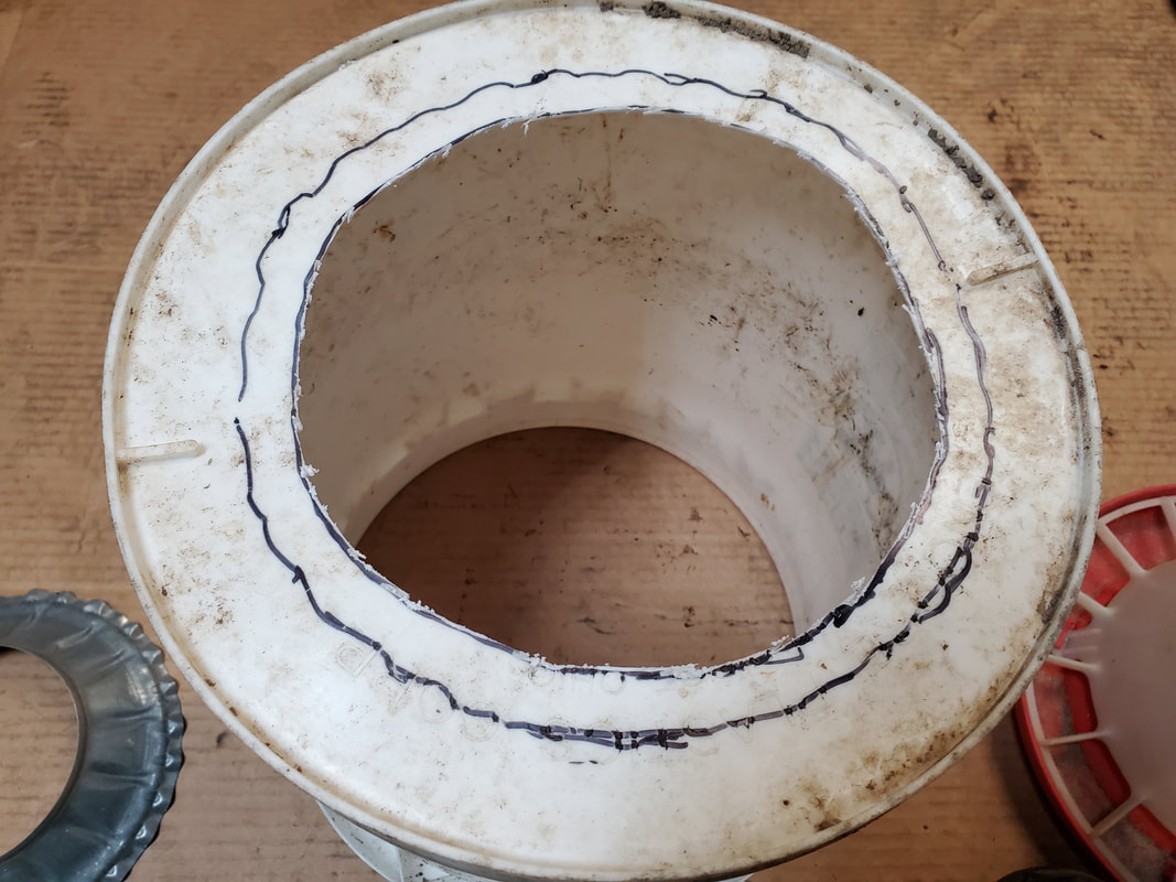
The latest chicken coop project, the Minivan Chicken Coop, is planned to be a little different than the other car coops in that it will be made to be a larger scale bulk feeder with the intent of being able to feed the chickens on a longer term basis, such as during a vacation. Along with the larger scale drinker cup plumbing apparatus, these bulk feeders would be filled with a whole 50 lb sack of feed, possibly more between the two, allowing for a long term feeding, even during regular times. This first feeder that I'm trying to make is to be made from a single 5 gallon bucket and a gallon capacity feeder with an open top.
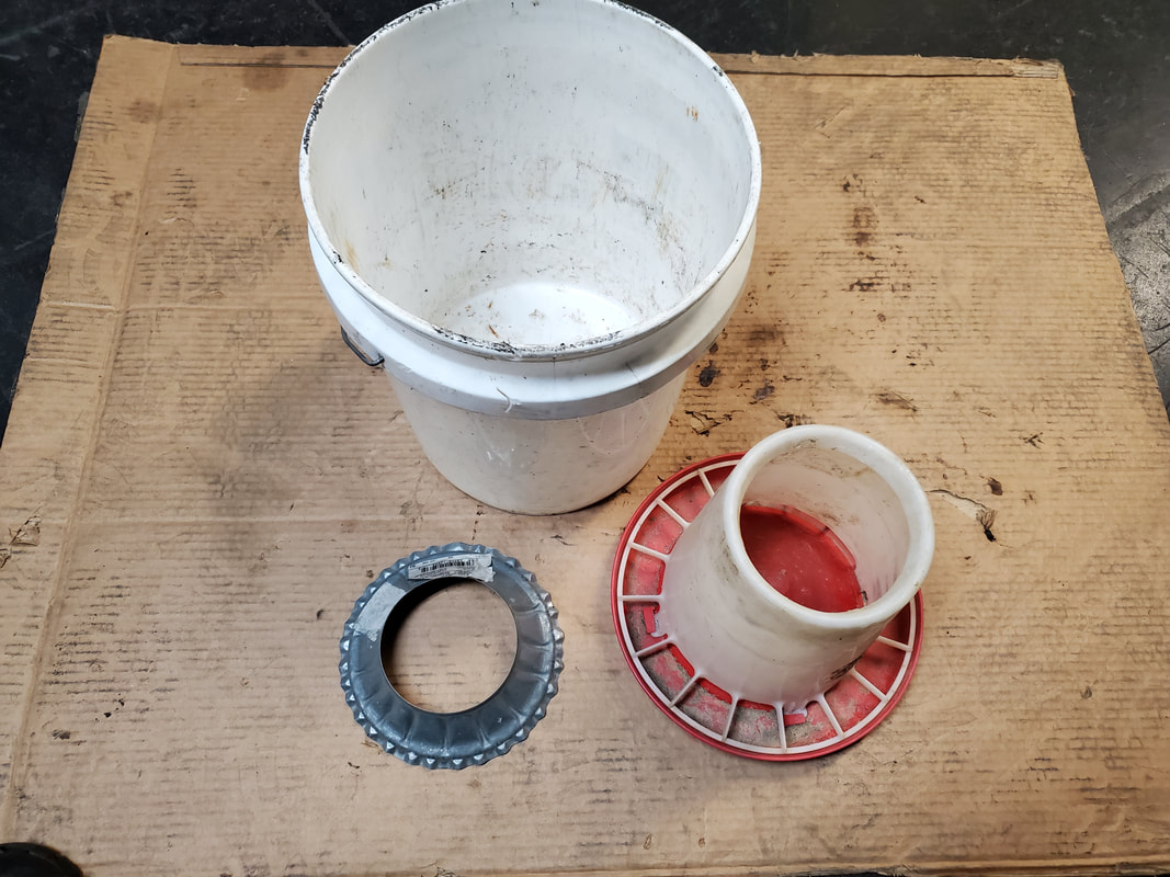
The pieces to be used for the bulk feeder.
First move is to prepare the bucket. This bucket was already holed from its previous use as a planter. The pieces to be used in this device are a 5 gallon bucket, the feeder and an RV chimney shield. I have to cut a large hole to allow for the chimney shield to be placed over as part of the hopper construction. I did this by laying the shield on the bucket bottom and tracing a marker outline, then removing it and tracing a smaller circle inside the first outline. It's this smaller circle that was cut out. 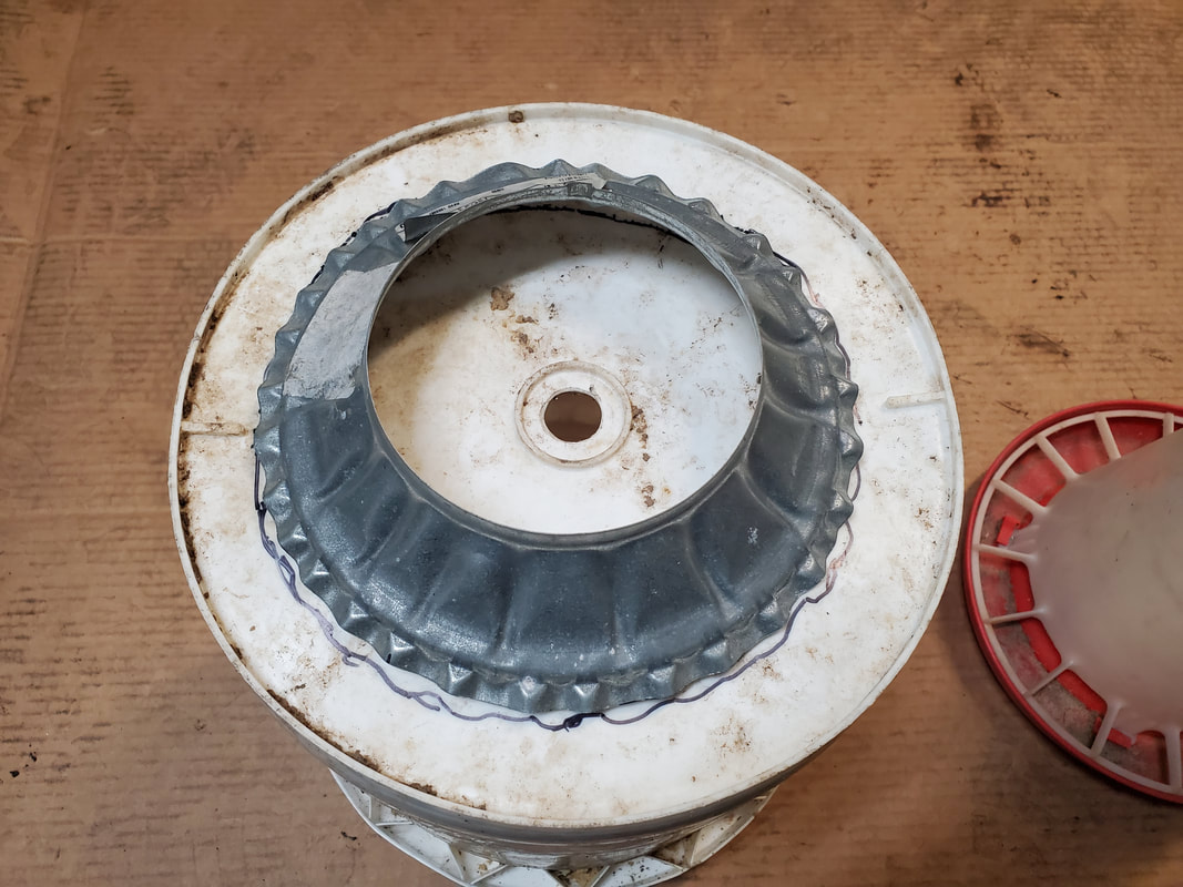
The RV shield placed on the bucket bottom to trace the hole to be cut.
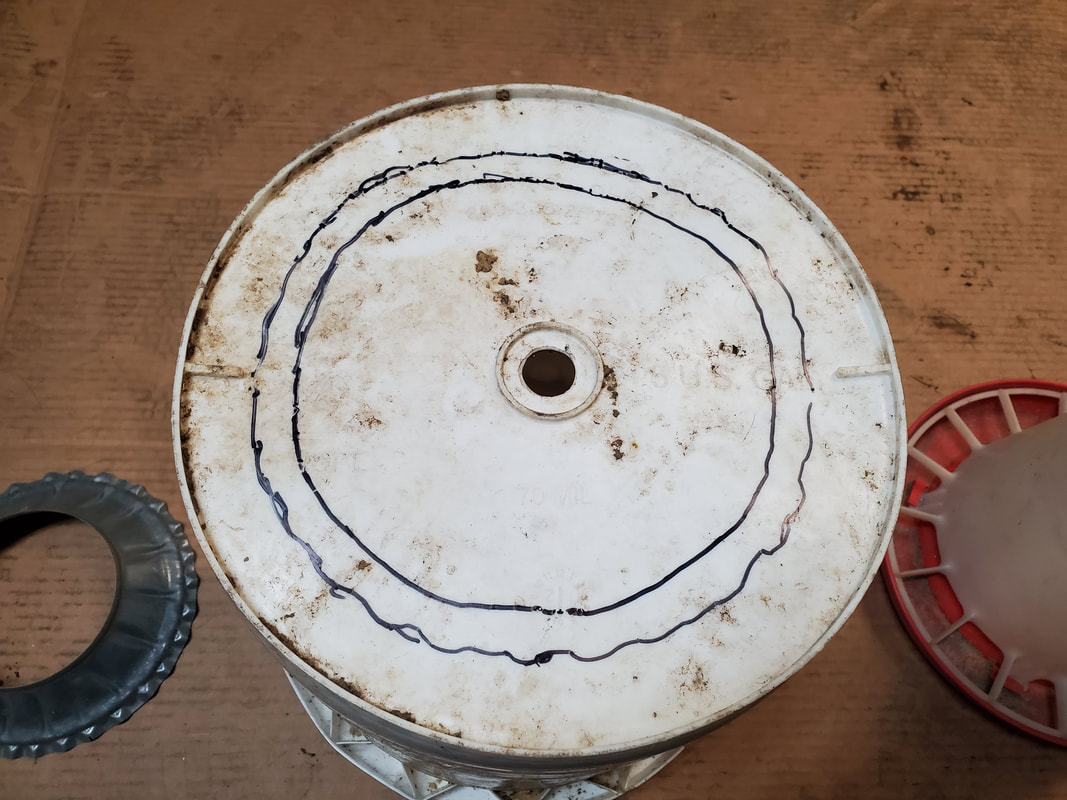
The two holes traced prior to cutting.
The hole cut out of the bottom, leaving a ring with the other line that was drawn.
With the hole done, I placed the RV shield back on the bucket bottom, covering the hole. The next move is to drill five small holes around the lip of the shield and into the outer edge of the hole, still inside the ring drawn on the bottom. Five small nuts/bolts/washers were used to secure the shield to the hole. 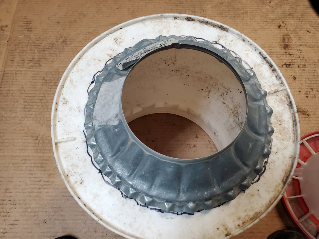
The RV shield bolted to the bucket bottom with the five screws though the five holes.
Next move is drilling another set of holes going through the top rim of the feeder and through the top edge of the shield. The holes are another set of five holes, drilled at an angle, through the top edge of the feeder and into the lip of the feeder. As before, bolts were used, except they were longer bolts to go through the extra material, secured with nuts and washers. 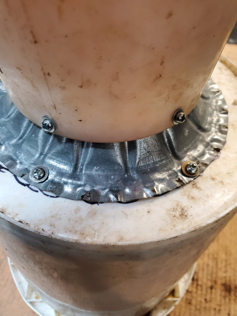
The commercial chicken feeder bolted to the RV shield with another set of five bolts.
With the feeder secured to the shield, the last thing is to seal the gaps and openings around the shield so feed won't spill from the gaps or provide intrusion points for moisture or dirt or anything else. This is where the hot glue came into play. Using it to fill the gaps around the bucket bottom and the RV shield, I sealed the gaps enough to ensure full closure. 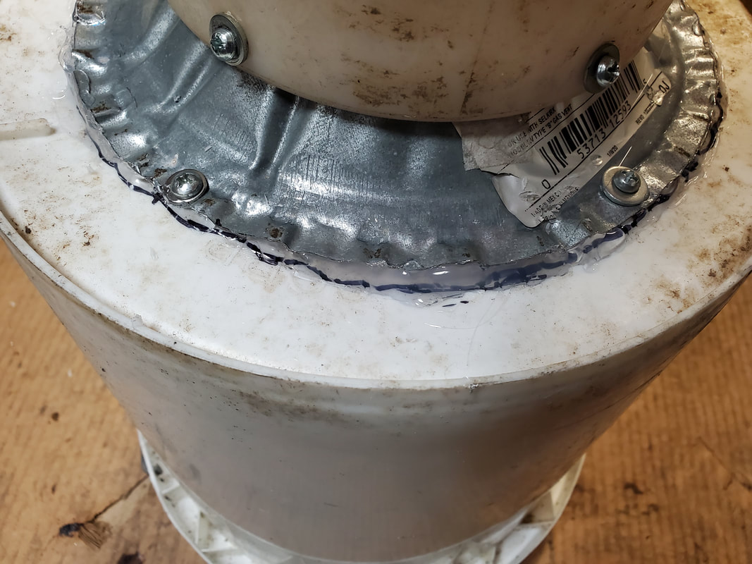
Hot glue used to seal the gaps around the RV shield and the bucket bottom.
The thing with this bulk feeder though is the idea that it will not be a standalone unit. Along with the other unit I still have to make, both of these units will be supported on a framework I still have to make that will help cradle the hoppers that will hold the bulk food. By themselves the bulk feeders would probably fall apart under their own weight. With the framework I'll make, the heaviest parts will be supported, and will look a lot neater in the van body along with the other apparatus I plan to install within.
After attempting to install this old trailer winch I had on our car trailer and doing a test only to find out the thing had a bad solenoid, I placed an order for a replacement unit. What I got wasn't the exact same unit as the old solenoid, but close enough to work. The solenoids on the winch have a dual set of contacts, since the machine has to be able to reverse. I had already removed the cover on the winch and had to fight to reassemble the winch body to where it would work. The cover was trimmed down some to allow for it to just snap back on over the internals without having to break down the winch again. First thing is first, pulling the old solenoid out. 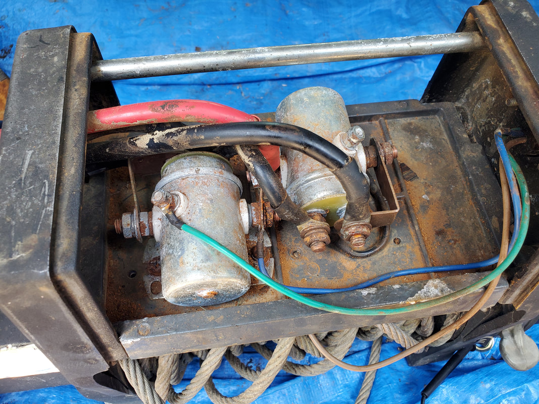 The winch with its pair of solenoids, the one on the right being the bad unit. I was able to remove the cables from one side of the solenoid, as well as the two screws holding the solenoid to the winch body. Allowing me to pull the old solenoid up, I was able to mount the new solenoid and hook up those cables I just removed. Once this was done, I was able to disconnect the cables and bus bar from the other side of the solenoid in order to hook that stuff up to our new solenoid. 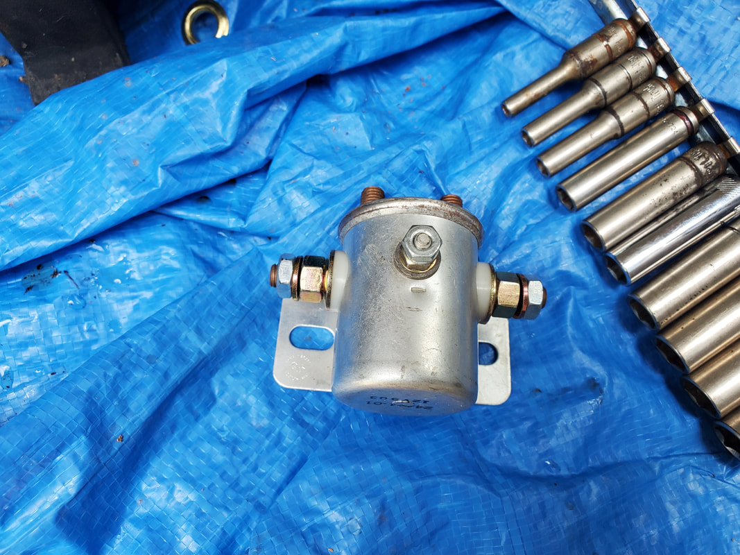 The new solenoid, slightly smaller than the old unit but still the same basic design. Because the new solenoid was slightly smaller than the old unit, the bus bar that was on the old unit had to have a new hole drilled to allow the bar to fit the contacts on the new solenoid that were more narrowly spaced. Once the new hole was drilled, I was able to get everything reassembled and secured on the winch body. 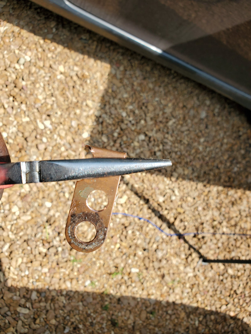 The bus bar with the extra hole drilled in place to install on the smaller solenoid. The test was successful on the winch, reeling in both directions. All this with a compromised winch control. The buttons are dry rotted and brittle but still enough to allow the device to work. I will have to replace this control assembly as it won't be long before this thing pisses me off with its inability to just work effortlessly in the field. That means back to the interwebs to see if I can find a replacement unit, or at least something that I could splice into the cable going to our winch. The control is pretty simple, just three wires, two power lines and a ground wire to activate either solenoid so I could probably get away with damn near anything in this case. 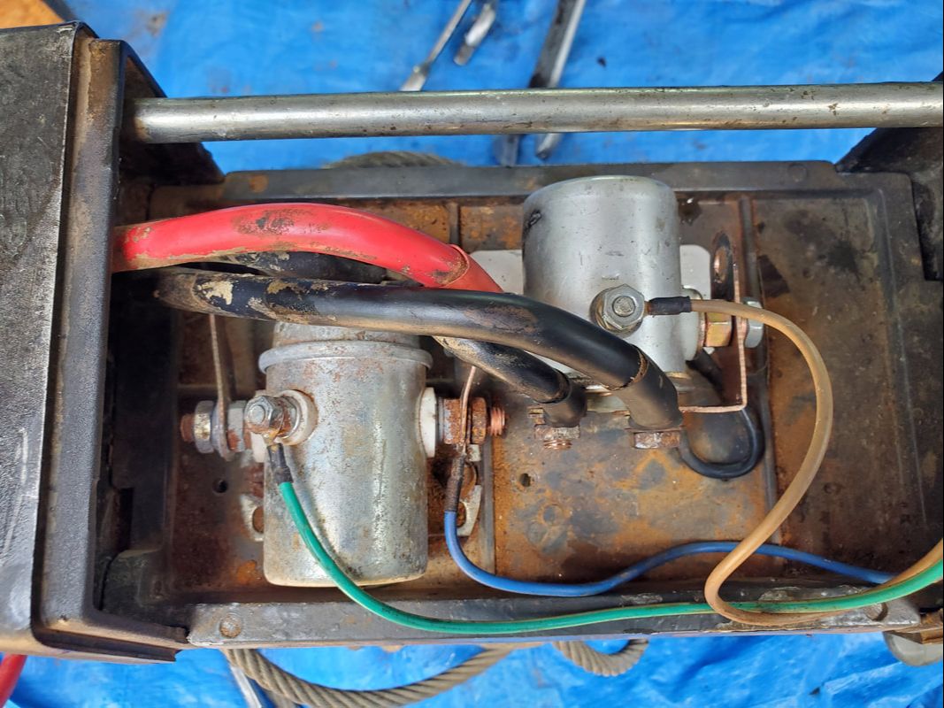 The winch with its replacement solenoid installed and ready to test. Along with the control switch, the next order of business will be to get some grade 8 bolts, nuts and washers in order to secure this winch to the mounts that I welded up on the trailer a while back. I'll also have to source an extra battery that I can use whenever I do need to use the trailer for a car pull. I kind of want to set things up to do a test just to confirm that the thing will work like its supposed to. I need to make sure that the bolts will hold, along with my angle iron mounting setup. Last thing I need is to have the winch snatch itself off while in the field then I'm having to scramble to use other winches to pull a car onto the trailer. With all the other little tasks completed on the Scion, I decided to take on swapping out the old spindle on the car with the junkyard spindle, which hopefully has a good wheel bearing in place. The whole process is pretty easy, just removing the brake hardware, CV nut, strut bolts, speed sensor, tie rod end and ball joint. To start things off, the wheel had to come off. 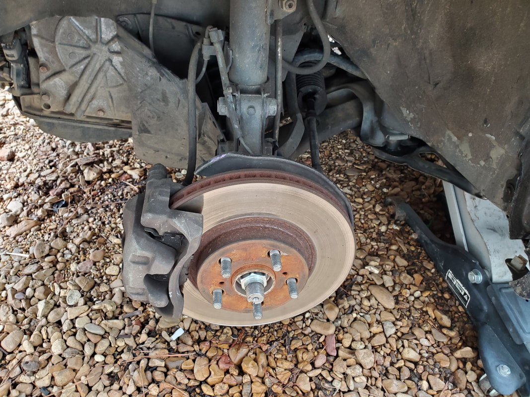 Old spindle assembly after removing tire. All the brake hardware, the caliper, pads, bracket all had to come off. With that little bit of business done, the speed sensor, held by one bolt, came off. The CV nut came off as this was rather easy with the impact wrench, as was the two big ass bolts on the strut. I had to beat on the tie rod end and the side of the ball joint to dislodge them as I wasn't using the fork, which would've resulted in damaging the boots. With all that taken care of, the spindle could come off. 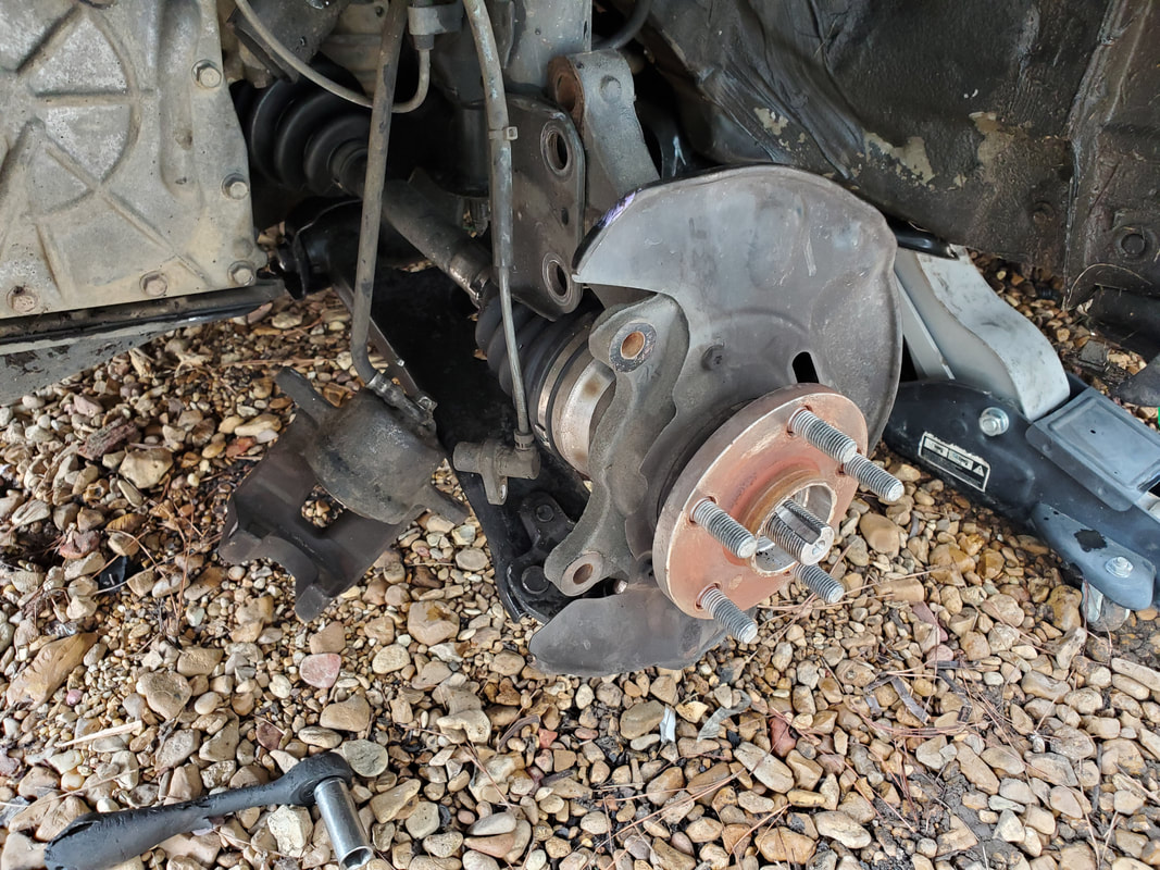 Spindle after removing all the components that needed to be disconnected to facilitate its removal. After removing the spindle, my quick test of rotating the hub confirmed my suspicion that the wheel bearing was shot. Rotating the unit had it scraping internally, showing that the wheel bearing was indeed failing enough to make the growling noise it was making the whole time. I'm not sure how this suddenly came to be but either way, the unit had to be swapped out. The junkyard unit did not make any kind of scraping noise or have any resistance that would be indicative of a bad bearing. I installed the junkyard spindle and started reassembling everything in reverse. 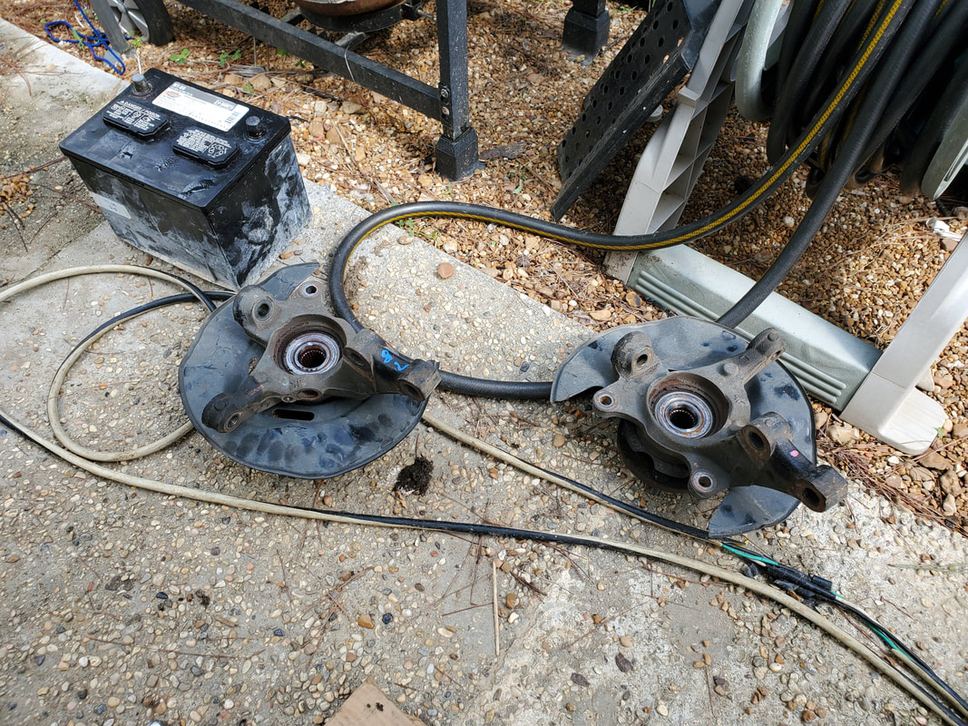 Pair of junkyard spindles, hopefully the wheel bearings are good. 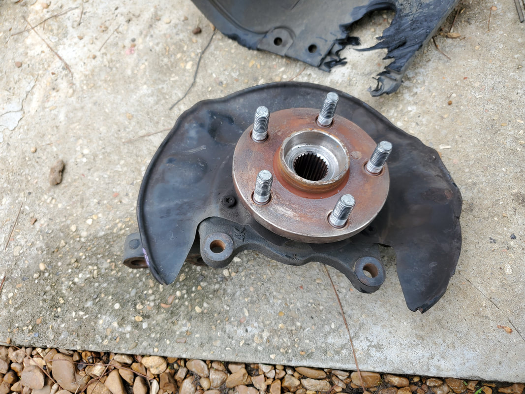 The old spindle removed from the car, confirmed to have a bad wheel bearing. This unit was actually a junkyard unit and had its wheel bearing replaced a year and over 100k miles ago. With the reassembly of the junkyard spindle, the car made its test drive, up to highway speeds, with nary a sound from the driveline. With that, the junkyard spindle swap out was a success. I can now order some new wheel bearings and take my time swapping out the old unit in the driver's side spindle and hang on to the other junkyard unit, taking time to replace it when that side does eventually go bad and in return swapping out the wheel bearings. 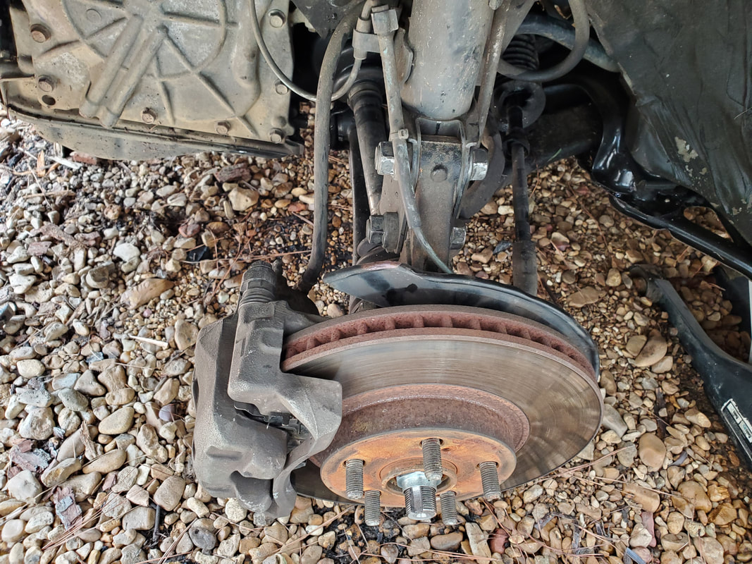 New junkyard spindle assembly ready to go, just gotta put the wheel back on and test drive this thing. With this taken care of, the work is still not done yet. There is a matter of a power steering leak that has been seeming to get progressively worse as we went along, facilitating the adding of oil almost every day. Now it does appear that the boots are worn on the rack and pinion, which will be my first place to start. But I will have to slide under the car, unfortunately while its running, to see if I can spot any other leaks that may exist, whether a hose or the power steering pump. At least I can comfortably say that I'm checking the problems off the list on the car. More than likely I'll keep addressing problems, even when the problems haven't fully surfaced yet. I'll probably start replacing other parts that I have a good idea of their possible failing, just to cut future problems off at the pass.
With the clockspring taken care of, there were a couple other things that I wanted to address on the Scion. For a while now, we've had a problem with the belt buckle on the driver's seat having a problem with latching the seatbelt. We would have to force it in a way where it will force snap the latch in place. This had to be addressed. One of the things we grabbed from the junkyard was a replacement belt buckle from the driver seat of the donor car. This had a length of wires connected to it so I had to take care to unplug everything and remove the buckle in one piece, as I did not want to go through the extra work of splicing wires from the old assembly to our junkyard assembly. First thing I had to do was remove the driver's seat from the car.
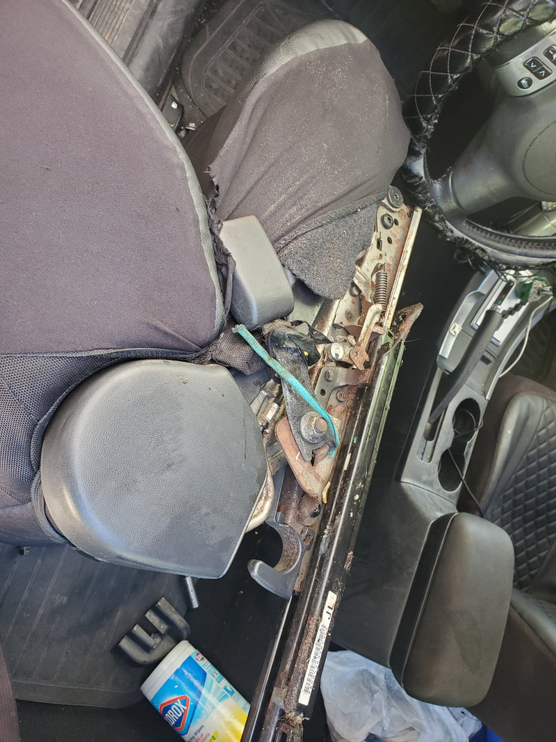
Removed driver's seat with old belt buckle prior to removal.
After removing the bad buckle and the associated plugs/wires, I bolted the new unit in place, using some zip ties to secure the wiring in the same points where the old wiring was snapped in place. I also had to take care of another small problem that I had when we first got this car, which was disconnecting a couple of cables that went to a couple of levers on the seat. I took time zip tying the cables together to tuck them away neatly under the seat before remounting the seat. 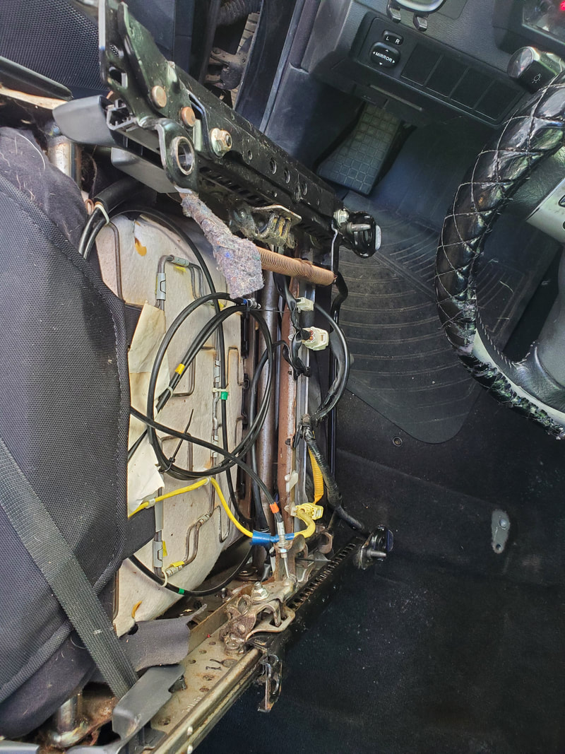
Cables and wires zip tied to keep things nice and neat prior to reinstallation of the seat.
Before remounting the seat, we took time to clean up on the floor under where the seat mounts. Never let an opportunity go to waste. After the floor was scrubbed and vacuumed clean, I remounted the seat, testing the buckle successfully. With that taken care of, I moved on to another problem that needed to be addressed, which is the brake rotor. 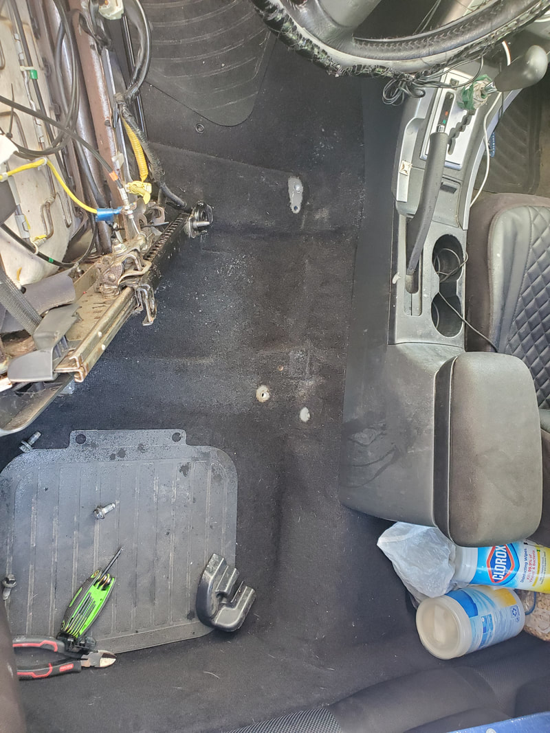
Cleaning up the floor prior to installing the driver's seat to complete the job.
When I changed the brake pads on the car before the engine was deemed shot, I found that the right rotor was damaged due to the worn-down brake pad digging into the surface of the rotor. I put things back together for the time being as there wasn't much of a choice and buying a new rotor locally wasn't my idea of good economics. This is where the rotor from the junkyard came into play. The unit, besides the surface rust, was thicker than our old unit and of course not gouged out on one side. The brake pads will scuff clean the surface of this rotor through use so all will be fine. 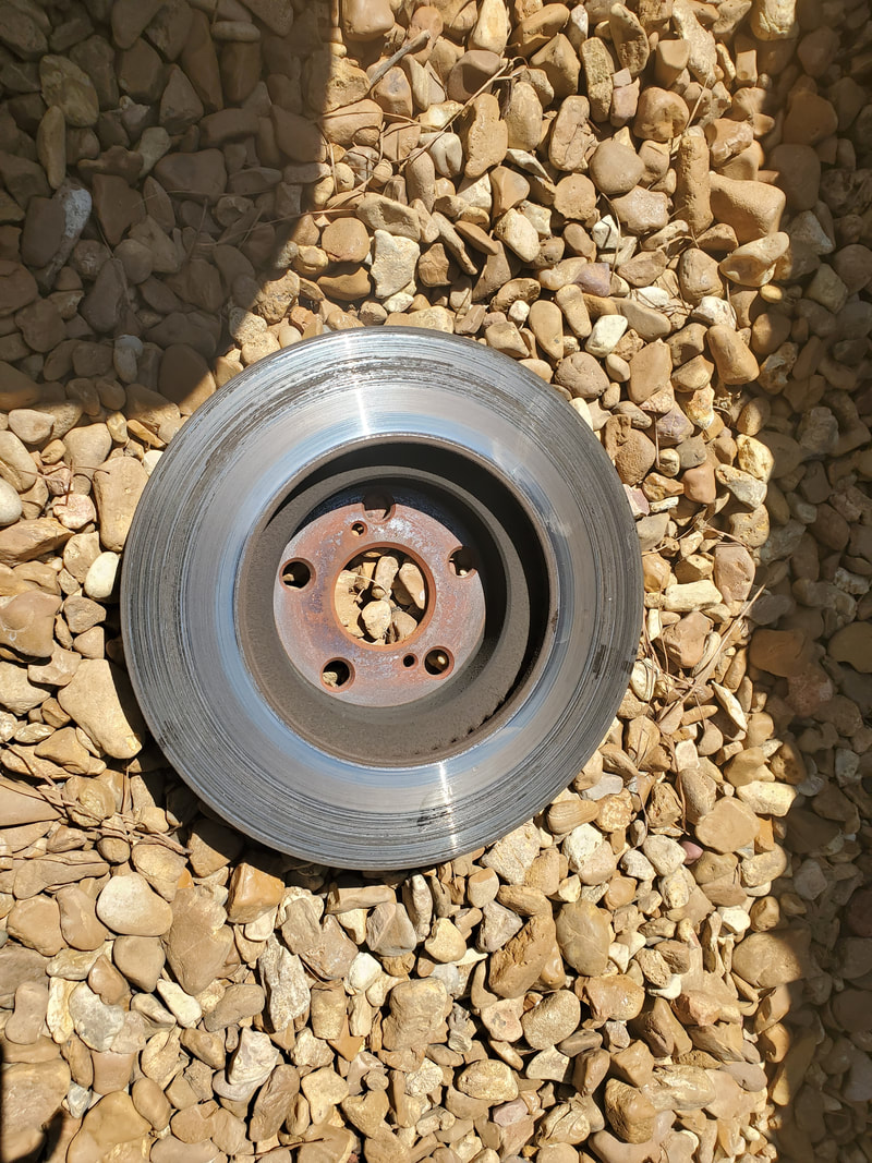
The gouged out old rotor that was removed.
To remove the rotor I had to pull the brake caliper and pads, then the bracket that holds everything in place. From there, the rotor just slides right off. Nothing more. The new used rotor went on and everything went back on in reverse. With that taken care of, another little task was taken care of on the car. 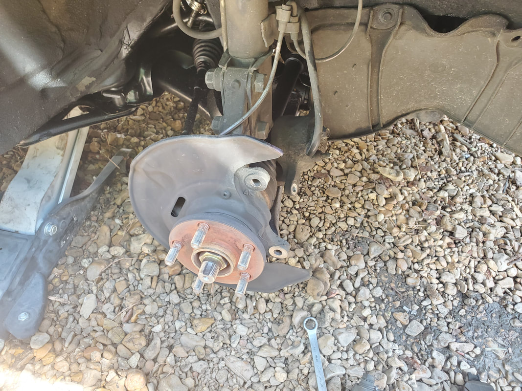
The spindle after removing the rotor. Later on these will end up being swapped out when I replace the wheel bearings in the donor spindles I got from the junkyard.
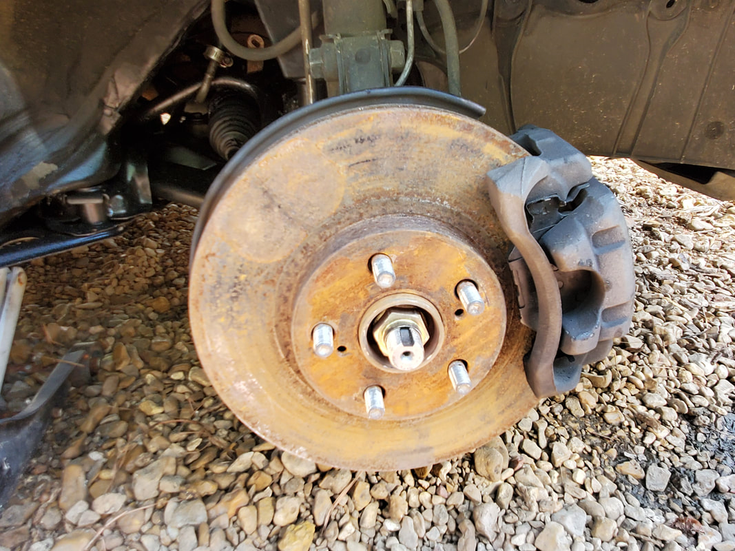
Junkyard rotor installed on car with all brake hardware reinstalled.
The last big thing that I need to do on this car is replace the wheel bearings in the pair of spindles that I also picked up from the junkyard. Theoretically the driver's side spindle has a bad wheel bearing on the car so hopefully the replacement of this spindle will fix that problem, otherwise I may need to revisit the idea that the new CV axle may be a faulty unit. I might even swap out the junkyard spindle on the driver's side just to see if it changes the noise that we're hearing and if so, then I might leave that spindle on and just replace the wheel bearing in the old spindle after removal. We'll see.
|
