|
Whenever one takes on this type of work, one can have high expectations that end up being shot down when the reality sets in. Such is the case when it comes to building an exhaust system from a random batch of parts. Trying to fit things with the hope of not having to do too much work ends up being a fruitless endeavor. When I started off with the advanced exhaust system on the Elco, I started off by chopping the excess pipe from the mufflers, so I can weld on some straight sections of pipe and test fit the mufflers to see what I would have to do next in the construction of the system. 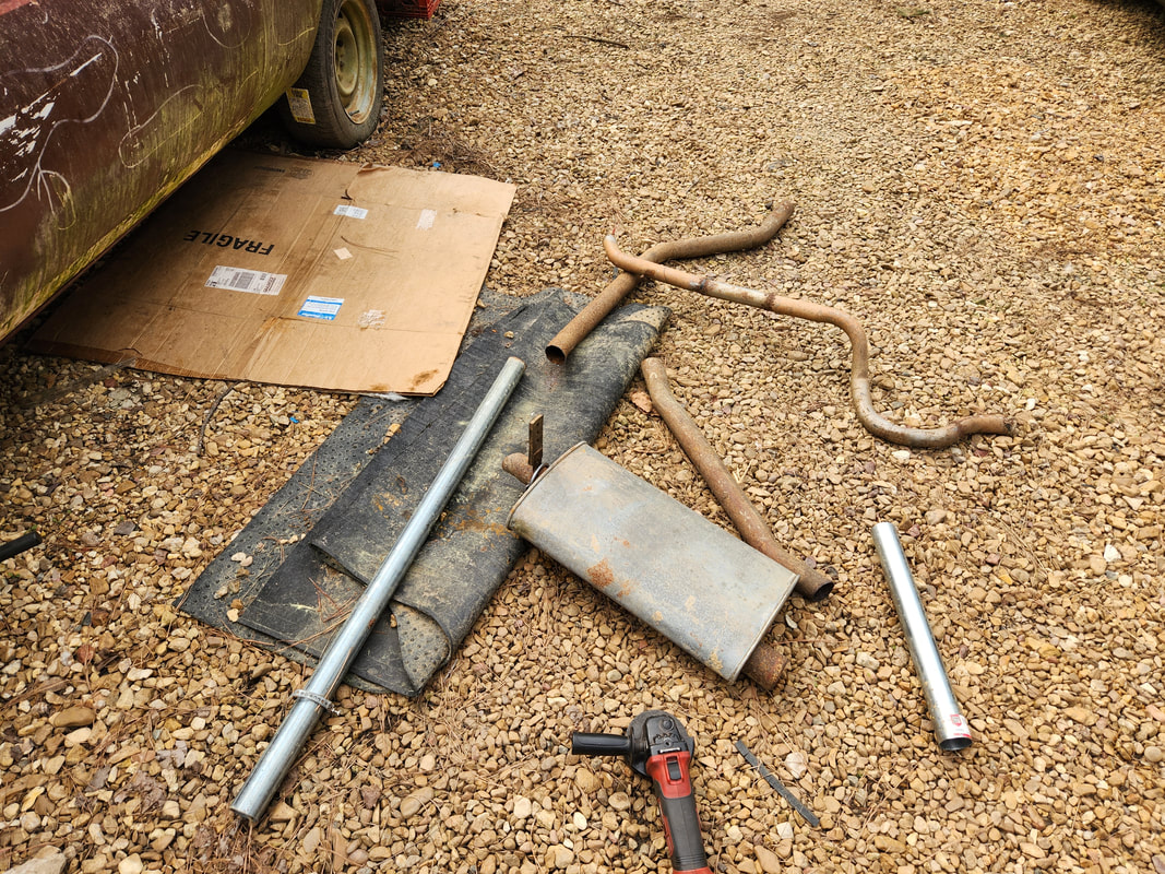 The fence posts and other random exhaust pipe sections that will be used for our exhaust system. I ended up digging out a couple lengths of fence post that happened to be the exact 2" diameter needed to fit in the flared ends of the elbows on the exhaust manifolds. After cutting the excess pipe from the mufflers, I welded the lengths of post pipe to them, then started the test fitting. This whole thing ended up being the beginning of the circus. 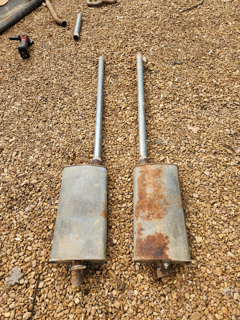 The mufflers with the straight fence post pipes welded in place. This will quickly change... The first thing I found was that the mufflers, by sitting in the muffler valleys, would require what amounts to an S-pipe attached to the input side. Since the input would be blocked by the floor of the car, the S-pipe would angle down and back straight to run along the floor. The pipe I cut off the mufflers yielded S-pipe pieces that I could use, so on the left side (the side I'm working first), I cut off the fence post I welded on and welded the short S-pipe piece that was cut, then welded the fence post back on at the other end of the S-pipe. The test fitting continued, as did the BS. 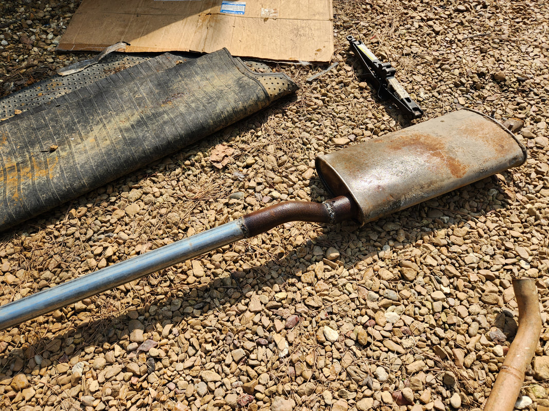 As can be seen here with the S-pipe welded to the muffler with the straight pipe on the other end of the piece. The test fitting had me ending up having to add another S-pipe piece at the front of the straight run, to line the pipe up with the output from the elbow, as things weren't as straight as one would've thought by just looking at it. The S-pipe at the front was what was needed at this point to allow the muffler to sit up in the muffler valley while still running straight along the bottom of the floor and still go straight into the flared end of the elbow. 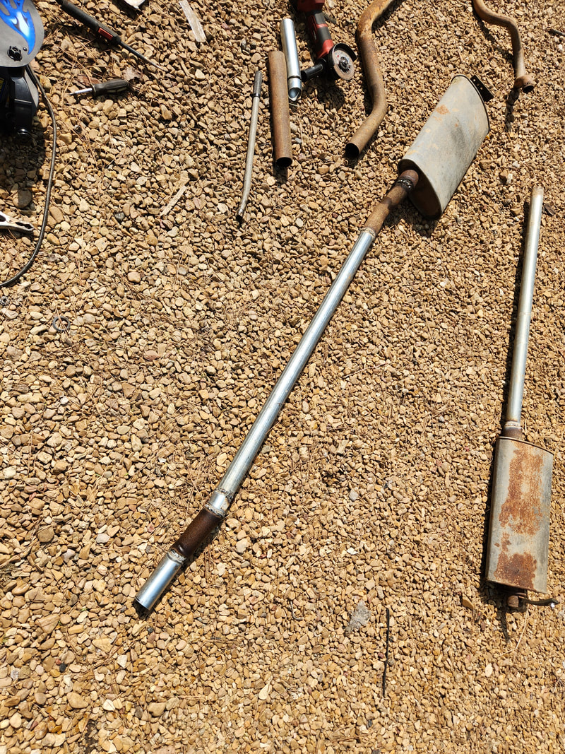 Even the other end of the straight pipe needed an S-pipe to allow for proper fitment under the car. 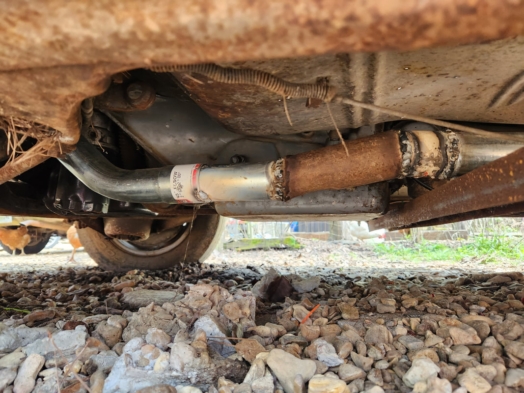 After inserting the front end into the elbow's flare, I added a little weld to hold the pipe in place until I can get a clamp on the flare to produce a crimp to hold things together completely. 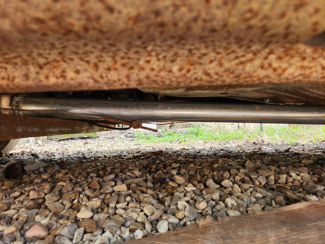 The straight section of pipe rests at a reasonable distance from the floor, with a very very minimal amount of space from the crossmember. At this point I had to mount the hanger for the system. At first I was going to clamp the strap at the output side of the muffler but because of the location of the muffler, the strap would have to go at the front of the muffler, with the muffler essentially hanging from the end of the pipe. I drilled a hole through the floor where I was able to place a bolt, washers and nut through the strap and on the inside of the floor to hold the strap, and the exhaust system, in place securely. 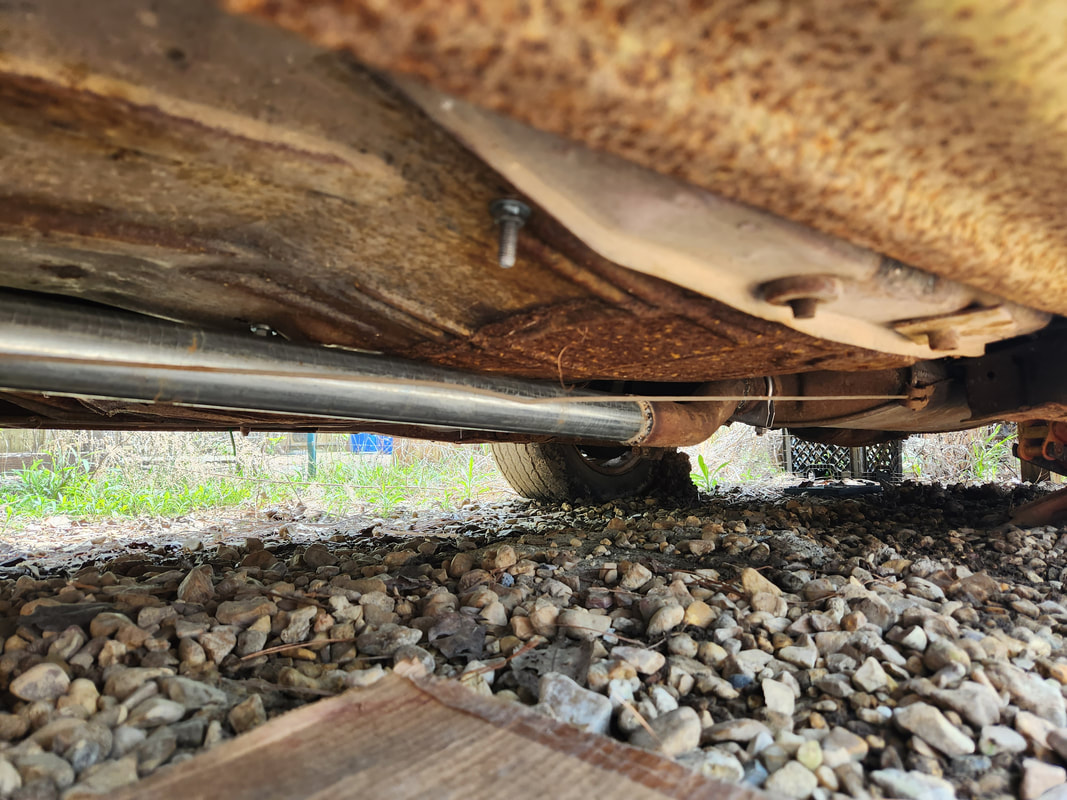 The muffler is tucked away nicely in the muffler valley, with the clamp and hanger in place at the front of the muffler instead of the rear. 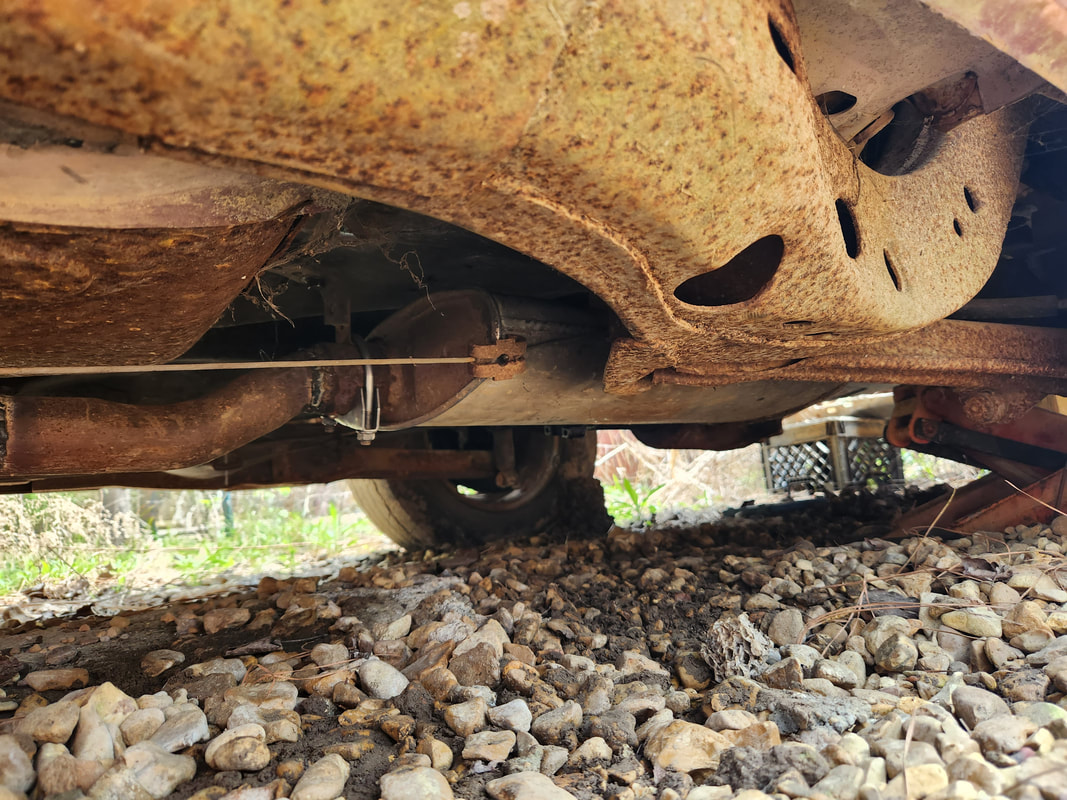 A closeup of the S-pipe and the clamp and hanger holding the muffler and pipe in place under the car. 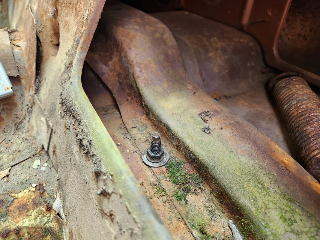 The bolt holding the hanger in place has washers on both ends, and is hung through a hole drilled through the floor, placing the bolt in the "trunk" area of the cab. With this side done, I can move to the right side, better able to approach the job with the knowledge of what I went through. Hopefully I can get the system assembled quicker by just cutting the pieces I'll more likely need and just start assembling and test fitting the system with those pieces already in place. Once that's all done and the exhaust system as a whole complete, I can move back into the engine bay. On a lighter note, there won't be any extra pipe on the end of the mufflers since their position puts the outputs just in front of the rear end, so I really couldn't even add axle pipes if I had them, so for the time being, we will be rolling with this seemingly incomplete system. I'll have to replace the mufflers with something smaller and different that would allow for something like side exhaust pipes, like mufflers with input and outputs on the same side. Shorter mufflers would place the output further away from the axle to allow for axle pipes.
0 Comments
Previously, I started off with the exhaust on the Elco by getting and extended section of pipe started from the exhaust manifold, with the pipe terminating at a point that makes it easy to connect the extended section of exhaust that will go to the mufflers. This involved connecting a 45 degree elbow with a flared coupling on the other end of the elbow so both ends of the elbow have flared ends. From there I welded one of the flared ends to the short piece of flange pipe on the exhaust manifold, with the whole manifold being a sort of "poor man's header". I still had to do the same thing on the passenger side. Only problem with the passenger side is the idea that the flange pipe was welded to the manifold since the flange bracket had broken bolts and could not be tightened or loosened as needed. This meant that I would have to test fit the elbow and mark it so I can get the piece welded on in the right position, so when the exhaust manifold is installed, the pipe would be straight. 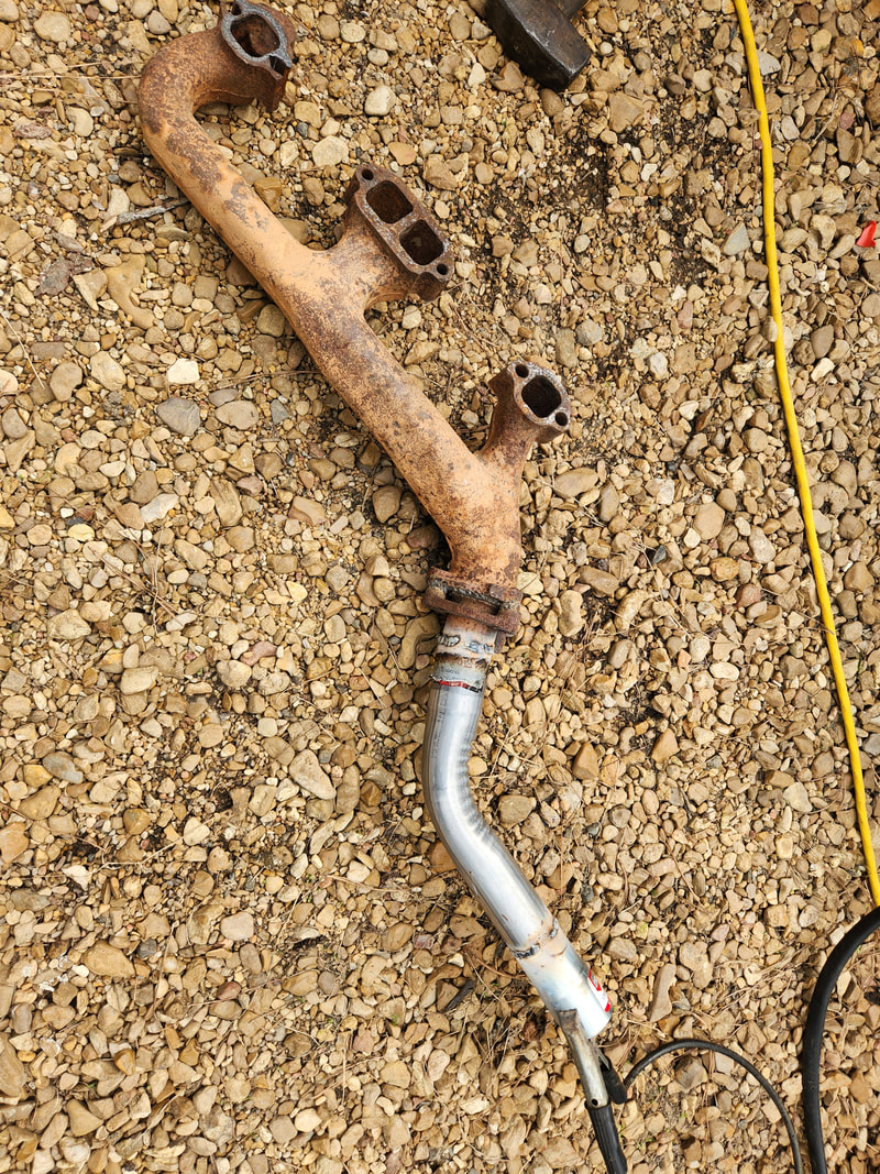 The elbow is welded to the short piece of flange pipe on the exhaust manifold while the flared coupling is also welded to the other end of the elbow, completing the "header". After marking the pipes, and even trying to get the angle I wanted that would require me trimming some of the end of the elbow, I welded the piece to the flange pipe. I installed the "header" back in the car, checking to see how the output lined up with the crossmember. Unfortunately, my crude fitting had the output at about a 10 degree downward angle, putting it right on the crossmember. I had to pull the unit off again, and cut a notch out of the end with the flared coupling, bending the coupling "up" and rewelding the piece, so when I installed the manifold again, the output would have the extended pipe passing over the top of the crossmember. 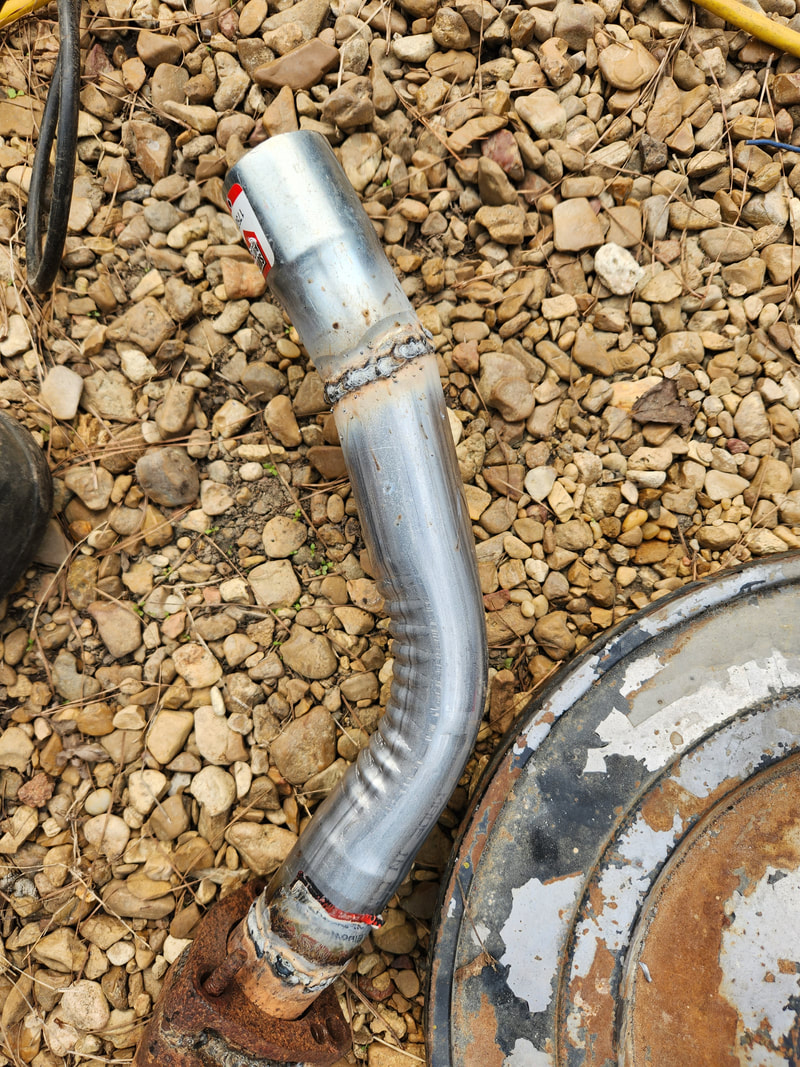 After a second fitting, finding the output to be at too low an angle to pass over the top of the crossmember, a notch of metal was cut from the flared coupling weld and the coupling bent in and rewelded. This of course was confirmed by fitting the piece of straight pipe to the flared end, confirming that the pipe will pass over the top of the crossmember with some room to spare so hopefully there won't be metal contact that will result in noise due to vibration. This too will depend on the placement of the muffler and how solidly its hung. On another note, the muffler valleys are in front of the rear axle, so this means the probability that our exhaust system will terminate at the output on the mufflers is more likely. There is a slim possibility that an elbow could angle out and possibly exit in front of the rear tires, but I'm not gonna hold my breath on that one. 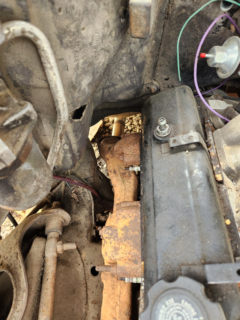 The exhaust manifold "header" installed in place after final welding on the elbow, note how the elbow pipe is straight in line with the rest of the exhaust. 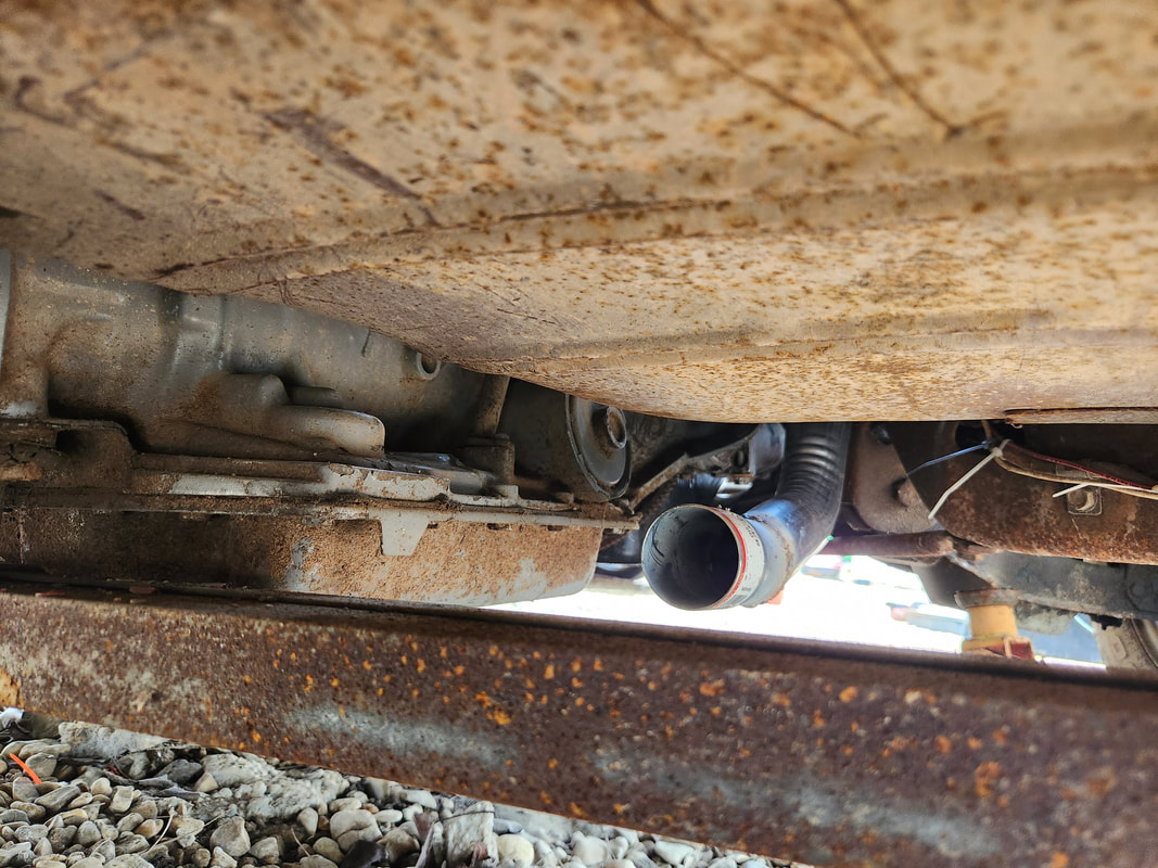 A shot from the crossmember showing how the output of the pipe will allow the pipe to pass over the top of the crossmember. With these two extended sections of exhaust installed, I can now focus on the mufflers. I'll be hanging the mufflers first, after trimming off any sections of pipe that can't be used on the system for the car. I'll end up using those sections of pipe to connect the muffler input to the outputs on our "headers", making for a rather quick and dirty exhaust system. Even with the piece of straight pipe that I got with the elbows, we should be able to get this exhaust system done at this point, allowing us to move forward, with the next thing being to set TDC on the engine so I can place the plug wires on the engine, taking care of that. I'll also be looking at installing the carburetor, as well as ordering a bracket piece to attach the TV cable from the transmission and ordering a radiator that fits the Monte Carlo, which happens to be a fit for the Elco. One thing I have to hand it to GM, making things pretty universal across the board for many years so interchangeability is high.
With a small batch of universal exhaust parts in hand from the auto parts store, I dragged the welder and some other tools out and got to work. I started by lining up the 45 degree elbows up, putting them on the stubs of the flange pipes to see how they sat, starting with the left side. On the left side, with the elbow fully in place, the bottom end would be sitting at about 15 degrees downward angle. I had to remove the elbow and trim off some from the narrower side, using a flared coupling on the flange pipe. Reason for doing this is to get the flared end of the elbow on the output side so I can just plug a pipe directly to the elbow. After making cuts and test fitting the elbow, I finally got the angle needed with which to weld the flanged coupling to the end of the elbow. It was then when the welder wanted to give me grief.
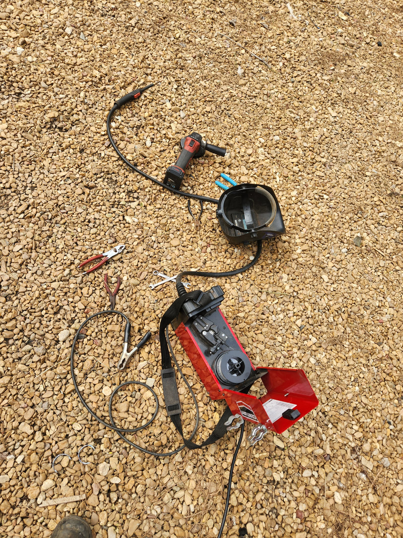
The offending wire feed welder that gave me grief and took up a fair amount of my already limited time, requiring a field repair.
For a while this welder would have a habit of stuttering in its wire feeding, with the wire sticking inside the gun, seemingly at the copper tip. I replaced the tip, with the same symptoms. I ended up having to break the gun apart and inspect the coiled wire tube, finding that the last inch or so of coil was burnt, causing the wire to probably stick on burrs and what not inside the coiled tube. I trimmed that last inch or so of the coiled tube off then adjusted the wire for the switch, reassembling everything to take into account the shorter coil tube in the gun. Once this was done, the welder was able to feed more freely, allowing me to weld up our elbow and flanged coupling as intended. 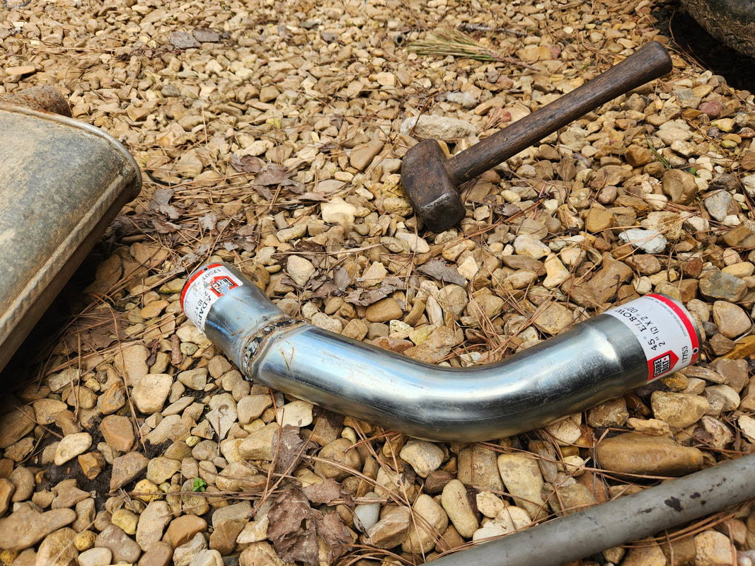
The elbow and flared coupling welded together after making all "adjustments" to ensure that the elbow will sit at the right angle to allow the rest of the pipe to fit right in and run straight back.
With the elbow done, I was able to do a final test fitting to confirm that everything would sit just right, as far as horizontal lines are concerned. I can now slide in a straight length of exhaust pipe into the elbow and run back to where I'll situate the muffler and fully assemble that portion of the exhaust system. I still had to attach the flared coupling end of the elbow to the flange pipe on the exhaust manifold. This would of course be done by welding. I loosened the bolts holding the flange pipe in place, allowing me to rotate the piece as needed, then removed the exhaust manifold entirely, welding the elbow to the flange pipe. 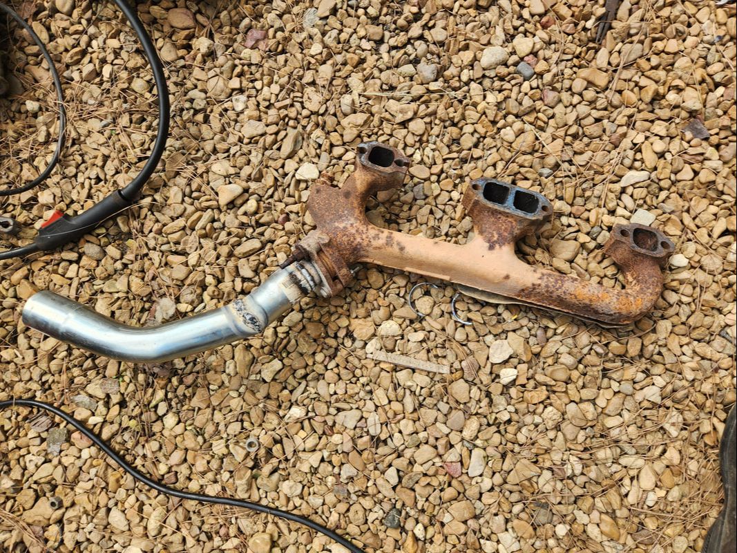
Left side exhaust manifold with flange pipe welded to the elbow/coupling assembly, making what amounts to a poor man's header.
With the elbow welded in place and still loose in the flange bracket, I installed the exhaust manifold/elbow back onto the engine. I rotated the elbow to get it back in line with the imaginary line for the exhaust system, then tightened the bolts to secure the flange pipe. With that, the left side of the exhaust system is ready for the advanced assembly. 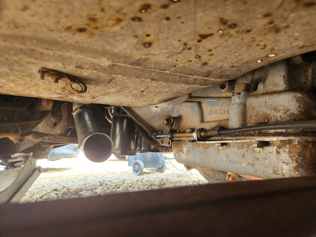
Looking just over the transmission crossmember at the bottom of the elbow, showing its straight line with the top of the crossmember. The pipe run will go over the top of said crossmember.
I will do this same sequence on the right side and have that ready to go before I start actually assembling the rest of the exhaust system, just so I can try to have everything done in a manner where its even with one another. At this moment I will probably just stop right after the mufflers, only adding a short straight length of pipe based on where the axle sits relative to the muffler valleys. If the muffler valleys are forward enough, I may just add elbows and route the exhaust pipe out to the sides just behind the rear wheels, otherwise for the time they'll just terminate under the car until I can source a couple of axle sections from the junkyard to make a full exhaust run straight out the back.
While the title may imply that not much went on in this session, that would be far from the truth. The problem with the starter, aside from trying to find bolts that were long enough to mount the thing to begin with, was getting a cable set up for it. This, despite being something that should be simple, ended up being a bit more involved. First of all, I did not have a dedicated cable with the ends on it for connecting to a battery terminal or the terminal on the starter. I dug out a length of red cable that was used for a stereo system, so it had a fuse block in line with the end that had a loop terminal on it. I couldn't have this so I removed the fuse box and had to use a propane torch to heat the meshed copper ends enough to solder the whole mess together. Heat shrink tubing finished up the that end of the cable. 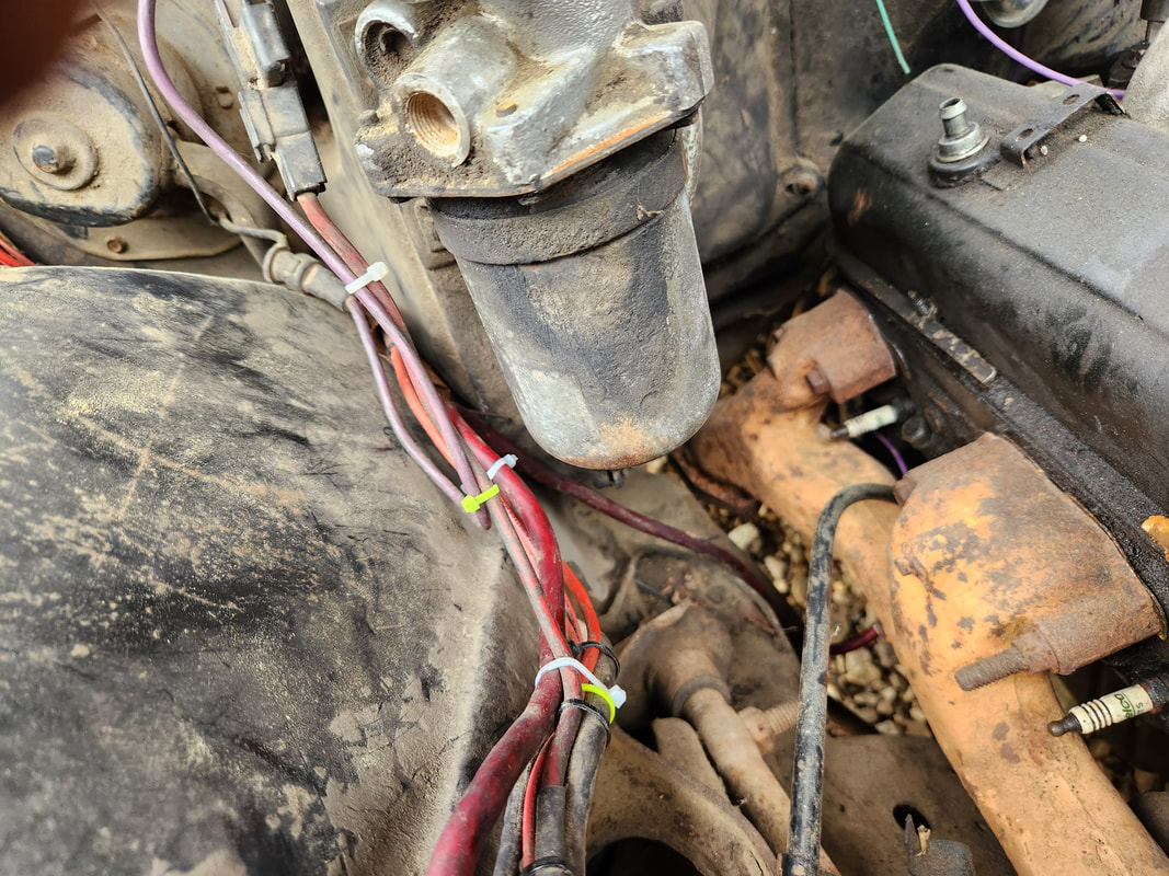 The main power cable for the starter is routed around a safe path and zip tied to the other bundles of wire, keeping things nice and neat. 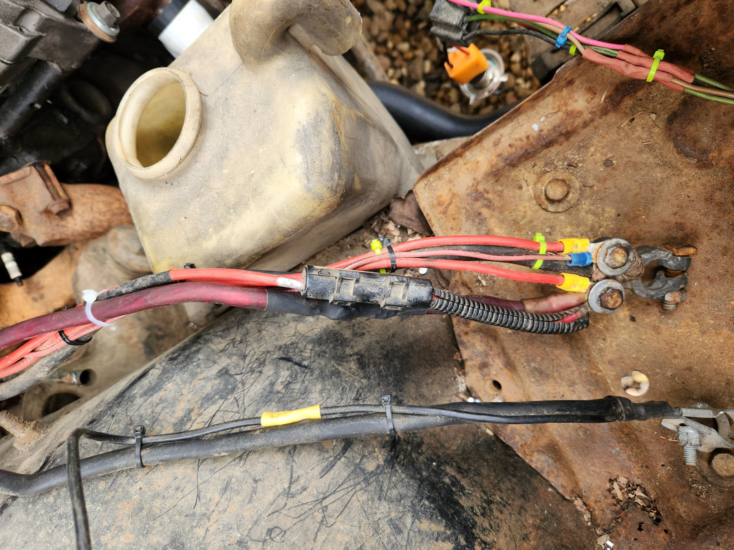 The power cable for the starter with its short stub with the loop terminal end connected. The terminal end is connected to the battery terminal, completing that part of the cable. I ended up having to dig out an obscure terminal end that had two holes in it for connection to two separate terminals, and use a heavy duty crimper to crush the heavy duty copper terminal around the end of the cable, after cutting the length I needed for the run from the battery terminal to the starter. Afterward, I trimmed the terminal down to just have one loop for the starter. I routed the cable around to pass around the exhaust pipe and connected the end to the starter. 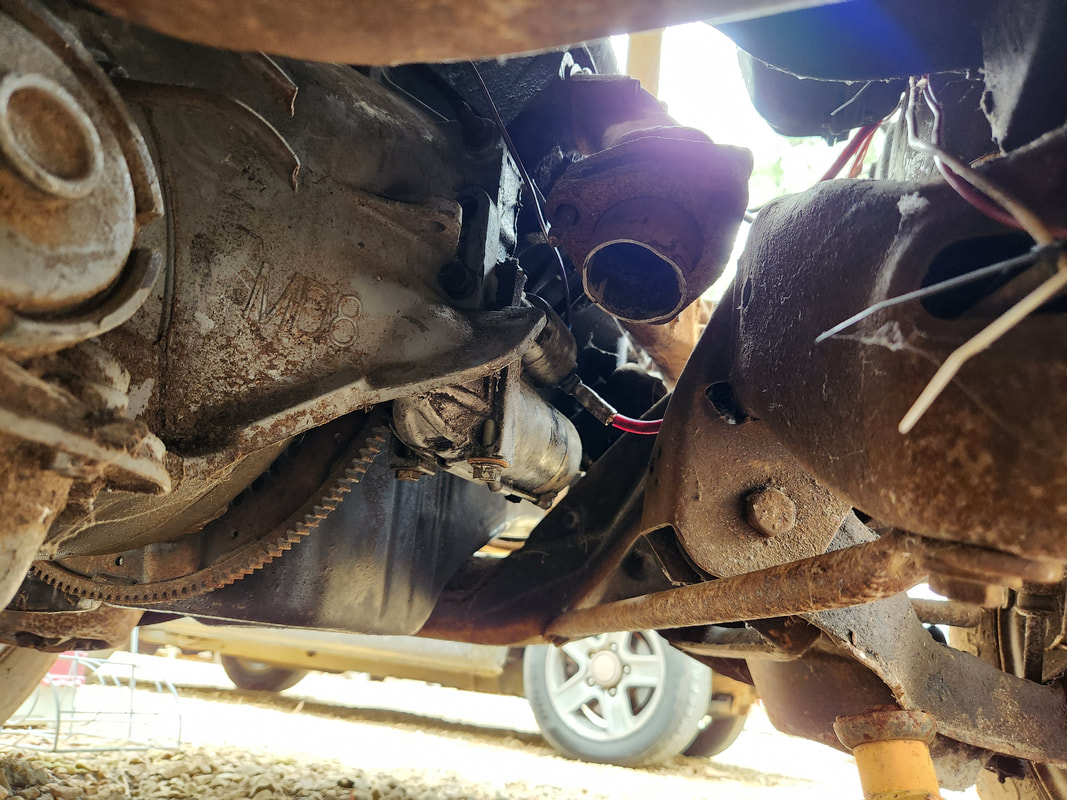 The starter is installed along with the main power cable and solenoid wire, making it ready to go. Also note the short stubby flange pipes that are in place on the exhaust manifolds, rendering the junkyard flange pipes unneeded. With the starter in place, another thing that I took care of was the transmission yoke I picked up from the junkyard. I had to grind the weld on the cut down tube and knock it free. I did grind a little too much in spots so hopefully the thing won't be too compromised that it can't be used. The yoke itself is still good, this is just the half that goes on the driveshaft tube. Either way, I was able to get the yoke in place so whenever I do run the engine, I can do so with oil in the transmission to keep it safe and wet. I could even theoretically put the transmission in gear to make sure the thing even works, based on the simple rotation of the yoke. 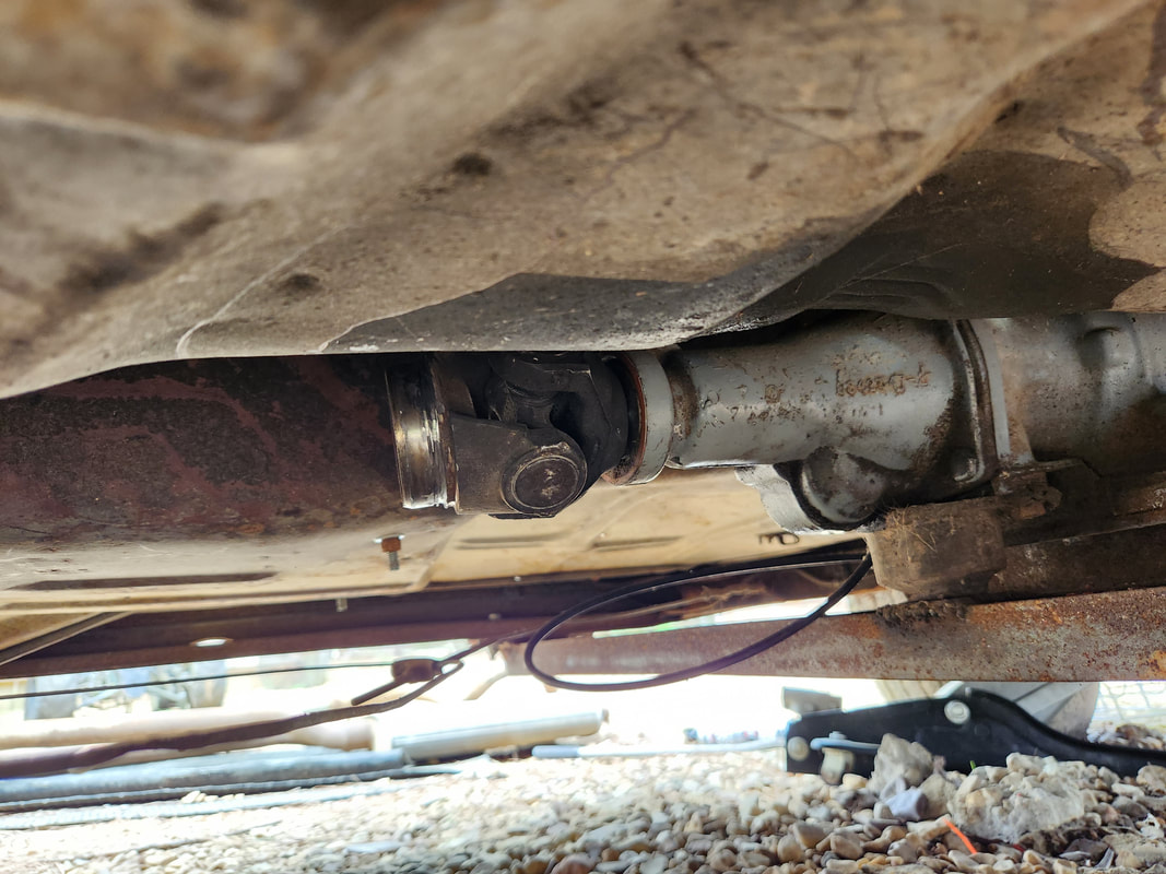 The transmission yoke in place after grinding and knocking off the short stub of driveshaft tube. One last thing that I did manage to address was the installation of the thermostat and its accompanying housing on the intake. As is always the case, I always install low temperature thermostats on my engines, in order to give me enough leeway on an engine's operation before it reaches critical. Especially during the hot summers here, having a low temp unit in place allows the engine to stay nice and cool, giving me more time to react when something goes wrong. In addition to the thermostat, I also installed the two radiator hoses onto the engine, just to get them out of the way. 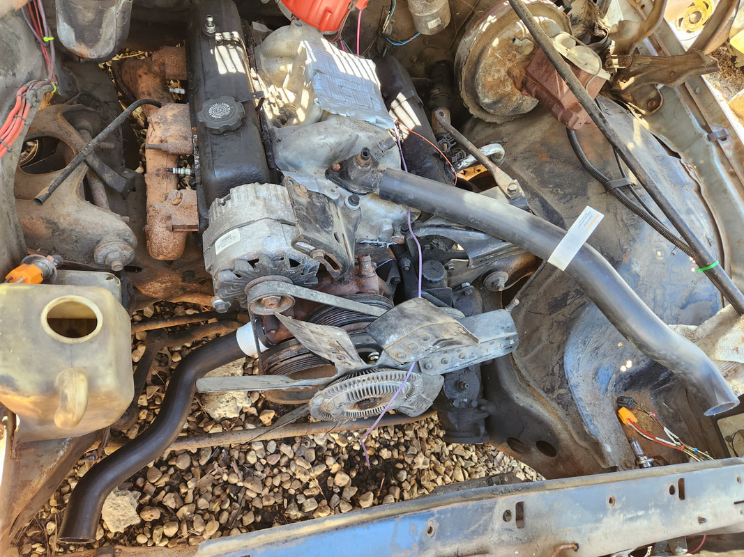 The thermostat and its housing in place, along with the radiator hoses, helping to get that out of the way for when I do install a radiator. Of course, I don't have a radiator in place, but when I do, everything else will be in place to complete the cooling system. There are still a couple things on that part, like a hose barb fitting for the intake so I can install one of the heater hoses, along with the second heater hose on the water pump. Also, I'll still need to add the oil lines from the transmission to the rad so that will fully complete that system. The next big project on the Elco will be the building of the exhaust system. Funny thing, I didn't even need the flange pipes that we picked up from the junkyard, as I discovered during the starter installation there were already flange pipes in place on the manifolds. Even though they were shorter than the pipes I got from the yard, they are in place and only need the coupling or flared ends of pipe fittings to build the system. I already have some mufflers and lengths of pipe from the scrap pile to help further build the system, so hopefully I'll have the exhaust system completed more sooner than later. As is always the case with daily drivers, something will need to be fixed on them, more on some than others. In the case of the Scion, its a lot more. Because the car sees 200 miles use everyday during food delivery. This is especially the case with tires. This car eats tires just like it eats brakes, and even motor mounts, which I will also need to replace, since they too are bad. Even after replacing the front motor mount, it turns out the mount to the rear of the engine, the one I had the most trouble replacing, is also bad, so basically, I have to replace all of them later. The tires on the rear of the Scion are in the worst shape, getting bald. After getting a pair of tires, I took a moment to swap the tires from the front to the back since the front tires were still in good shape. 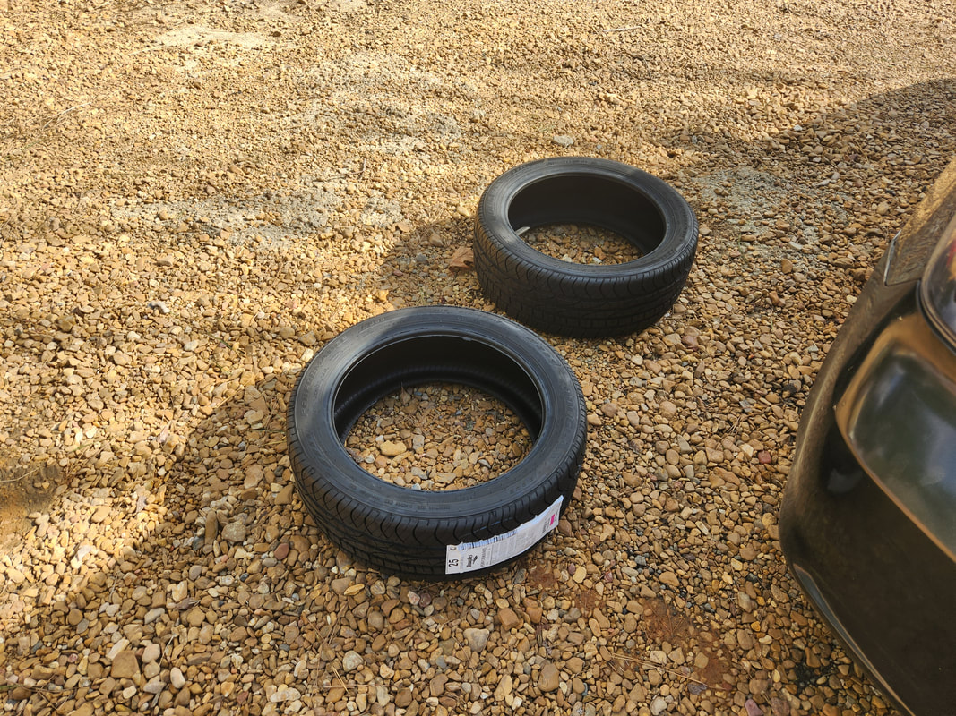 The new tires, fresh off the Walmart tire center's shelves. Even though we could've just let the tire shop swap the tires around from the rear to the front, since they charge for this little bit of service, it only made sense to just swap them around myself and let them install the new tires on the now front rims and be done with it. Another thing to make note of, these rear tires were slightly larger than the front tires, which was part of a problem with supply, we were only able to get this size tire. Of course, the new tires we got were the proper size, not the larger ones, so once this job is done, the car will have all matching tires. 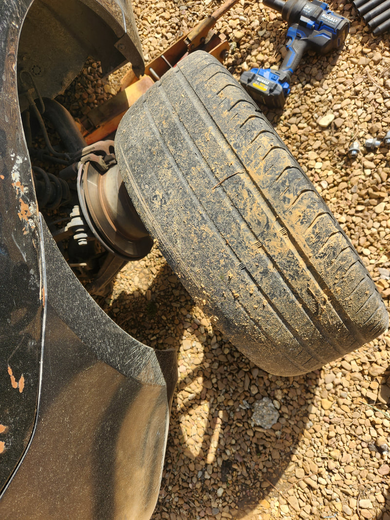 The rear tires were well on their way out, as can be seen here. Of course, as this cycle always goes, eventually the now rear tires will reach the end of their life and we will end up going through this crap again, and again and again, but whatever, it is what it is. Now, another thing that could be done to help alleviate this issue is being able to grab replacement tires and holding them in cold storage so this whole process can be done faster. Of course, being able to rotate tires properly so they all wear at least somewhat evenly, would allow us to just replace the whole set on schedule as it needs to be, versus doing this replacement in pairs crap. 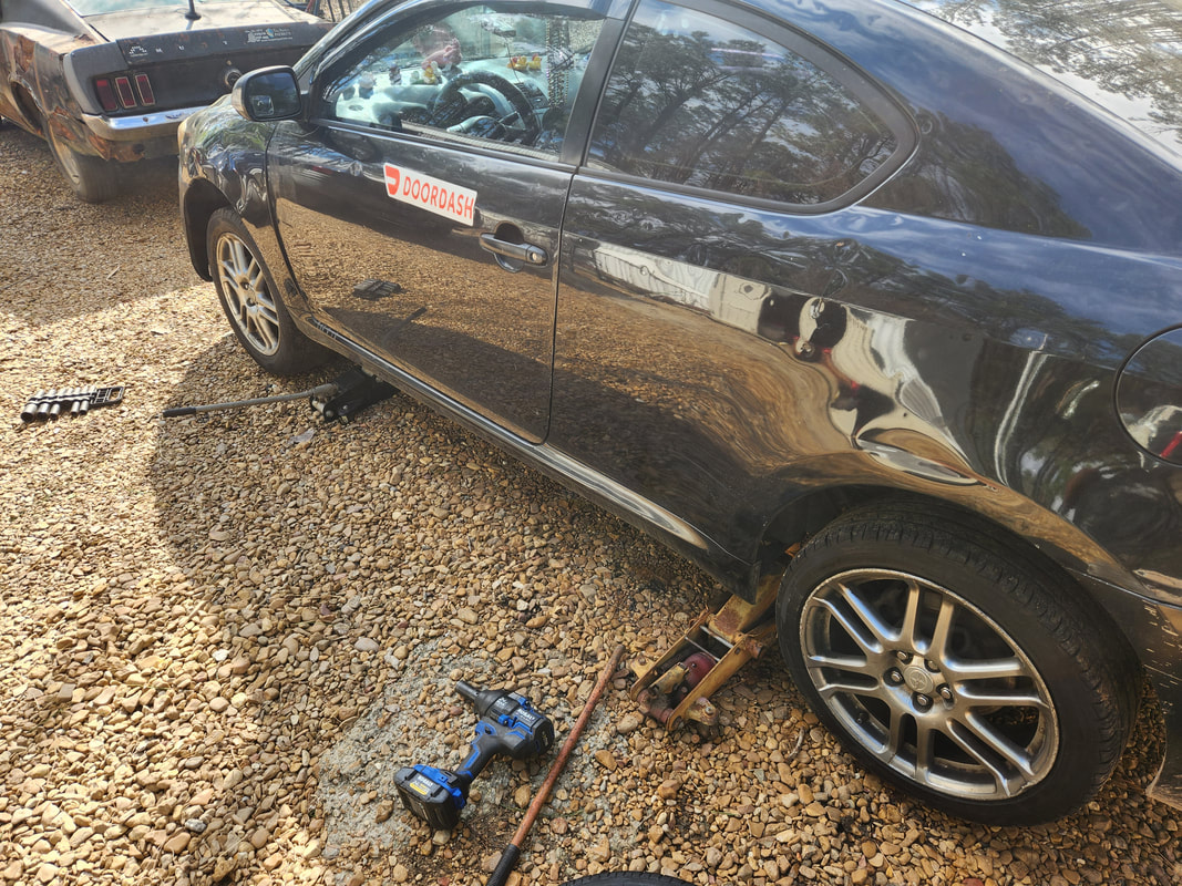 Finishing up the swap around of the rear tires to the front on the car. As stated before, the Scion will need all four motor mounts replaced, which will be another shitshow, just like before. I also need to replace some suspension parts on the car and as an aside, the AC line that we had to replace is finally back on the car and the system charged up and blowing snowballs once again. The work continues, and continues, and more... Among all the stock of parts I had on hand that needed to be used up, an aftermarket shifter was one of the parts that I was glad to have on hand. The Elco needed a shifter since the car originally had a column shifter and the linkages I would need to get are somewhat hard to come by. In this case, the aftermarket shifter fits the bill. There were a couple things that would have to be accepted, like the cut down shell that would leave a large opening around the bottom of the shifter base. I also had to drill a hole in the center hump to route the cable through in order to connect to the transmission. This whole process was not quite straightforward however. It took a lot of fitting before I got to the point where things started working in my favor. 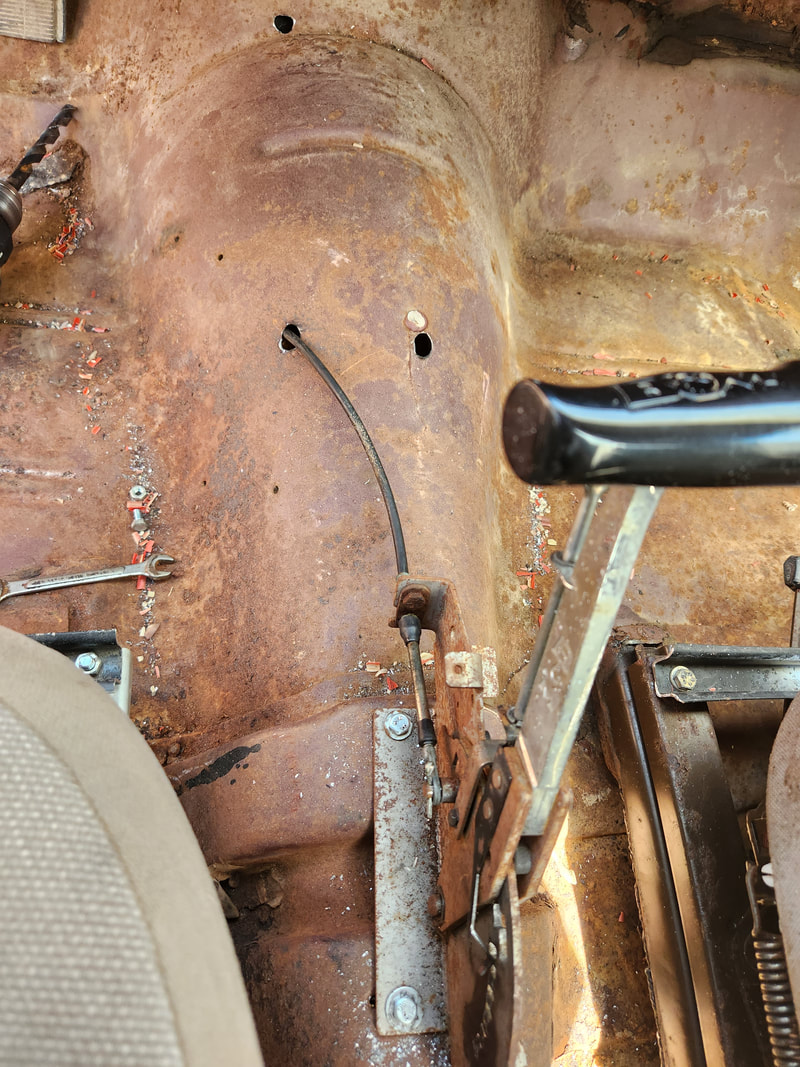 The replacement cable from the shifter, routed through the third hole drilled in place just to the left and forward of the shifter. Note the other holes that were drilled prior. The first hole that I drilled to route the cable placed the cable opposite the position it needed to be in. I drilled another hole just in front of the shifter and routed the cable through. Unfortunately, the cable was mounted to the right of the transmission body, putting the cable at such a sharp angle that when I did try to cycle the shifter after hooking everything up, the plastic guide tube in the cable broke, rendering the cable useless. Luckily, I had another shifter, one salvaged from the 73 Mustang, complete with a cable. I removed the cable from this shifter to use on the Elco shifter. Another thing I had to do was add the lever that came with the batch of brackets that came with the shifters. I needed this lever for the 700R4 in order to hook the cable end lug to the shift linkage on the transmission. I did have to do a bunch of test fitting of the bracket that mounts on the bolts for the oil pan in order to get the position where I needed to place the bracket so the cable would be able to cycle properly. 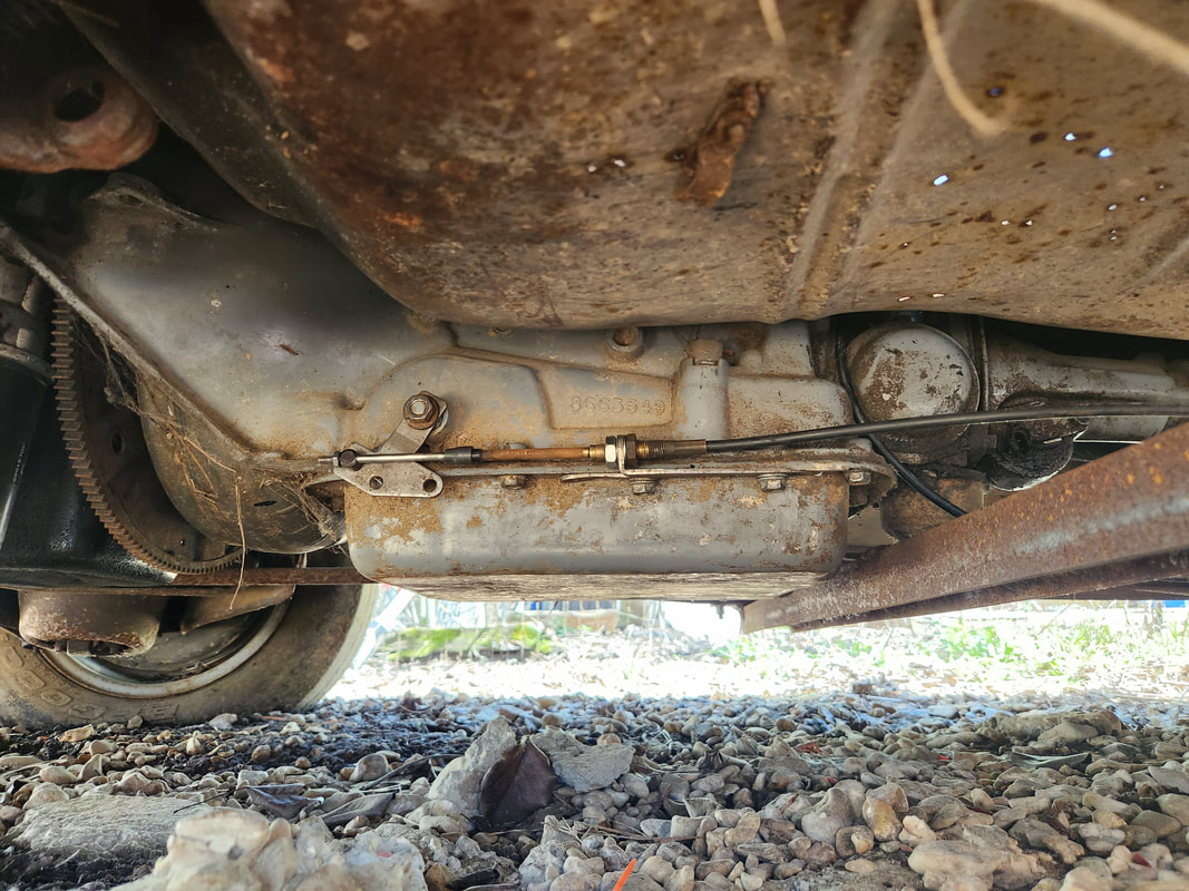 Straight side view of the transmission, showing the lever added to the 700R4 to connect the shifter cable to it. With the cable routed through a third hole that was drilled to the left and just in front of the shifter, I had to coil the cable to get it where it would line up parallel to the transmission and the cable bracket. I had to test fit the position of the cable nuts to align everything with the lever. After getting everything aligned, I was able to finally get the shifter to cycle properly, locking in park as intended and cycling into all but the 1st gear selection on the transmission. The shifter was originally for a 3spd so since the 700R4 is a 4 spd, I can go through all gear selections except 1st, which is fine. 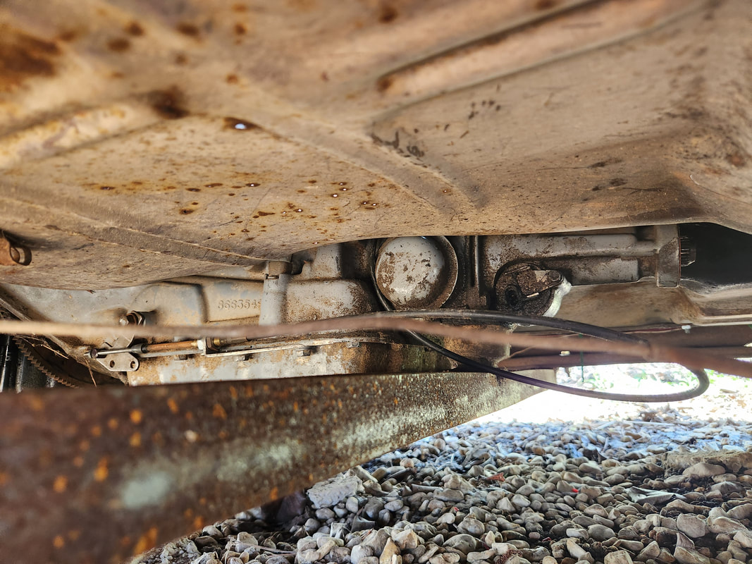 Another angle from the rear of the transmission, showing how the shifter cable coils around to point back forward towards the shift linkage on the unit. With the shifter all operational, I was able to get the shell back on the shifter assembly and wrap up the whole shifter job, which had royally pissed me of for the whole day. With that done, I got myself ready to hit the junkyard, in search of more parts, most of which would be used on the Elco. I needed to get a starter for the engine, which would help me set TDC to place the spark plug wires that I also got from the auto parts store. I also needed to get two flange pipes for the exhaust manifolds so I can connect to these in the making of a complete exhaust system. Lastly, if I could find one, I wanted to get a driveshaft that was long enough to work on the long El Camino chassis. The only car that would possibly work here is a 4dr B-body GM, such as the Caprice, Delta 88, and similar box style GM boats from the 80s. Best case I would be building a driveshaft from this piece to fit in the Elco, worst case I'll have the bones for a shop to build a custom shaft, namely the yokes. 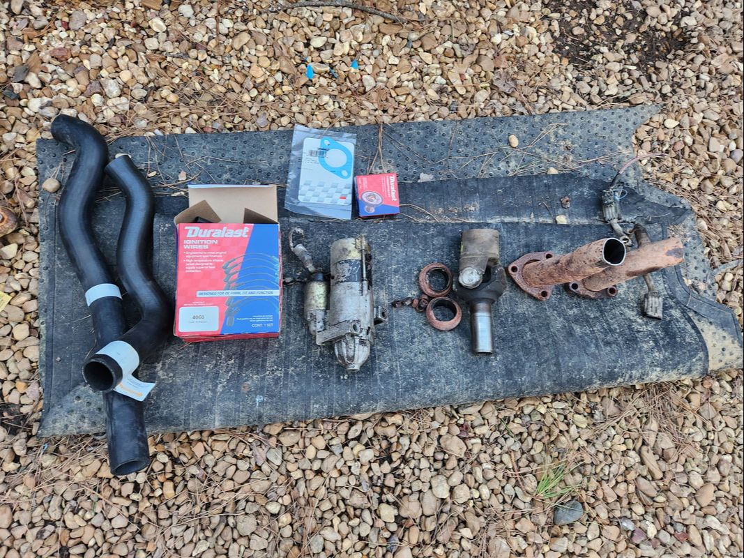 The shifter with the shell installed back in place after the shitshow that was the installation of this shifter. I ended up cutting a couple short flange pipes from a late model truck, complete with O2 sensors. I also found a starter off another late model SUV, a smaller newer starter or the Vortec SBC engines used in the late 90's trucks and SUVs. This would obviously be an improvement over the noisy and larger starters that were used in the 80's SBC's. Lastly, I ended up getting the transmission yoke and U-joint assembly from a 4dr Caprice driveshaft. Why not the whole shaft? Well the damned thing was bent. I wasn't about to pay for the whole shaft when I would be cutting it up anyway. I cut off the last few inches of the driveshaft, which would allow me to grind off the yoke end intact, for use in a new driveshaft, whether one I built or one the shop builds. With these and the other parts from the auto parts store, I can get to work on the Elco putting things together.  The batch of parts, from both the auto parts store and the junkyard, ready for installation on the Elco. After getting these parts installed, all I need to get is a radiator and oil lines installed, along with the rest of the exhaust system and a battery and some fuel so I can get the engine started and tuned, while keeping the transmission safe by having oil flowing through the machine. The yoke in place will allow for the transmission to be filled up without it leaking out from the tail.
In another short installment, I managed to take a moment to install my newly received temperature gauge on Truckstang. Unfortunately, the stock gauge did not seem to want to work, whether because of the sending unit or the gauge itself being defunct. I can only imagine even if the sending unit was faulty, the gauge should've done something, but it did not. I made sure to get a gauge that came with an electrical sending unit, versus the mechanical unit that tends to be more commonplace in these universal gauges. While I've had good luck with these, the only problem is having to route the metal probe/cable around and through to the top of the engine where the probe itself would be secured in place. With the electrical sending unit, I only have to worry about routing another single wire through to the engine bay.
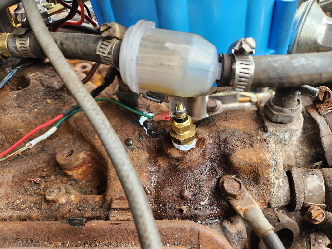
The new sending unit is installed in the spare port on the intake since the other sending unit is in a tight place making it difficult to remove.
Since the stock sending unit was right under the HEI distributor, it would've been a little more difficult to remove the thing without possibly disrupting the distributor somehow. Luckily, I had another port on the intake where I removed an old emissions related manifold fitting, leaving a 3/8" NPT opening available. With a reducer bushing, I was able to secure the sending unit in place, just across from the stock sending unit. I had to add a little extra wire to the length of wire that I secured for the run from the gauge. I took time to route the wire along the same path as the existing wiring, zip tying everything in place to keep things nice and neat. Even after passing through the firewall, I continued to follow the wiring over to the engine, needing to add only a few inches extra. Heat shrink tubing helped cover the couple solder joints I did have to do. 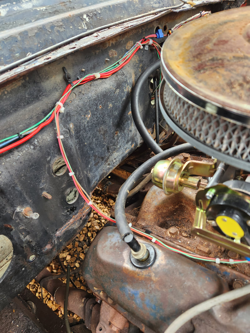
The single wire for the sending unit is routed neatly along the same path as the wiring going to the choke.
In the cab area, I had to add another single gauge mount bracket, since the triple bracket was fully occupied. While I could've stuck with the USB charger that had the voltmeter in place for my means of measuring system voltage, I wanted the dedicated voltmeter in place that I can use. I had a couple single gauge mount brackets in stock so this was no big deal and I had the new gauge mounted right next to the triple gauge bracket. I tapped into the existing wiring from the triple gauge, connecting ring terminals to the terminals on the voltmeter gauge to get power to the new gauge. 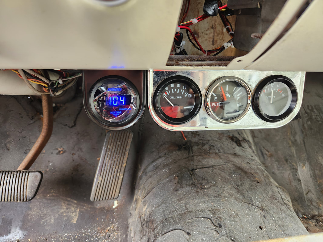
The new temp gauge installed in its own mount next to the triple gauge mount, with power applied.
With that, the temp gauge is ready to go, once I get everything back together with the transmission. Hopefully once I rebuild the thing and get it back in the car, we will be on the road testing the car since that's the only thing standing in the way of getting the car on the road. Other than verifying the driveshaft is straight, we are about ready to go.
In our quest to get back to working on the Elco and ultimately finishing the car, there were some things I had to dig out to use on the car. Some of these parts I've had the whole time and never took time to dig this stuff out, one of which was a shifter for the car. I had a B&M shifter that I originally had in Rustang a long time ago when the car still had a C4 transmission in it. Along with the shifter itself came the cable brackets for use on Ford, GM and Chrysler transmissions. The bracket on the cable was for the Ford C4 but since we have a 700R4, we'll have to switch over to the GM bracket. Unfortunately the body for the shifter had been trimmed down to fit the center console on Rustang so when I do install it on the bare floor in the Elco, there will be space around the bottom of the shell and the mounting base.
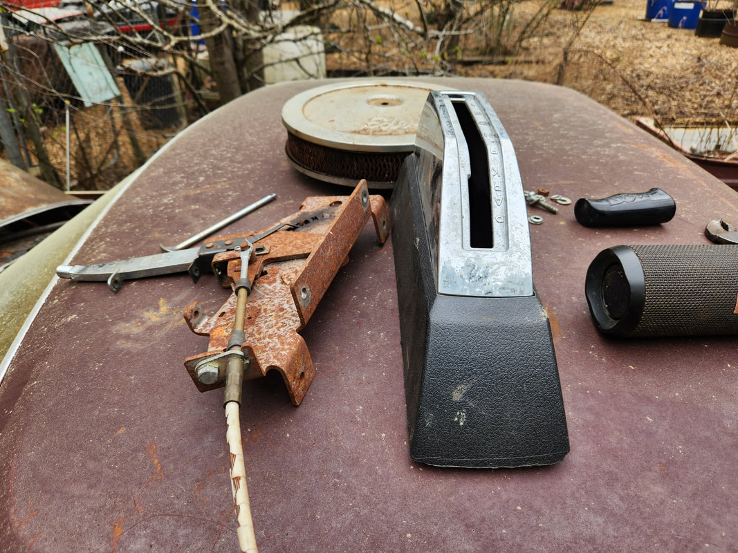
The old B&M shifter that used to be used in Rustang in its automatic transmission days. It'll now be used on the Elco.
One of the first things I had to do was line up the base to drill holes to secure the shifter down. Even though I would be using regular hex bolts to hold the shifter down, I would not be using nuts underneath to hold the bolts, I'll have to more or less cut threads in the sheet metal of the floor using the bolts. After drilling one hole, then lining up and drilling the other holes, I was able to force thread the bolts through the holes to hold the shifter down. If this didn't work, I'd have ended up needing another set of hands to hold the bolts while I applied nuts from underneath. 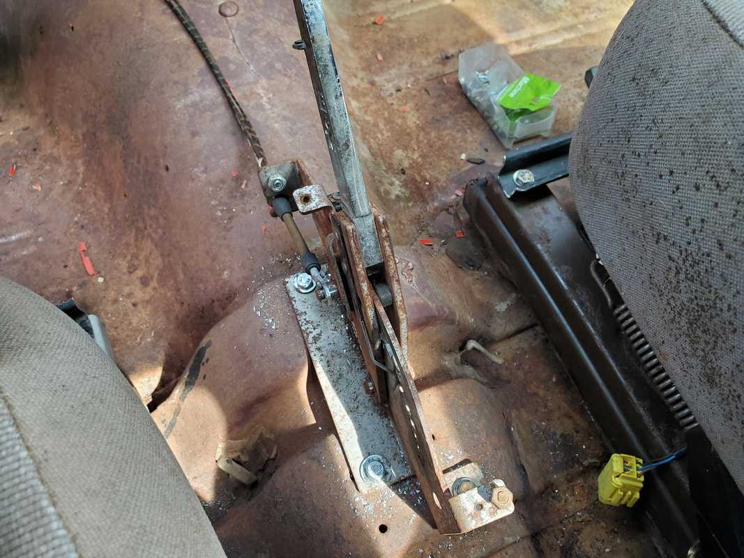
The shifter is bolted down to the floor using regular hex bolts force threaded through regular drilled holes.
After sourcing a small screw and nut to hold the shell in place, I got the shell installed and the locking rod clipped back in place which allows the shifter to ratchet and lock in whichever gear is selected. It's kind of a goofy design where it requires the shell to be partly installed over the lever before the locking rod can be installed, then only after the retaining pin is secured at the bottom of the rod can the shell be snapped in place. I installed the handle on the lever and secured that, with the next thing to mess with being the cable itself. 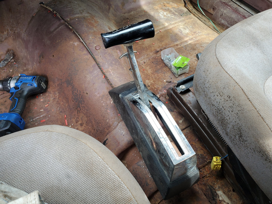
The shifter with the shell installed fully. Unfortunately there is a large gap around the bottom of the shifter due to the cut up body. I'll try to see if a replacement shell can be sourced later to replace this unit.
This part was a simple affair, with just a simple drilling of a large hole at the front of the hump in order to route the cable through. The cable would have to be routed forward of the shift lever on the transmission so the cable can be curved around to run parallel to the transmission where it will connect to the bracket and the lever itself. 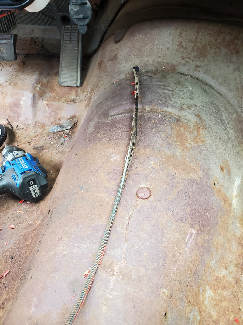
The shifter cable with its missing plastic skin, routed through a hole in the front of the transmission hump on the floor.
In our next episode, I'll be sliding under the car in order to curve the cable around and hook up the bracket and fully secure the cable, along with test shifting the shifter to see if it operates the lever on the transmission properly. The cable on the shifter has no skin on it as can be seen in the picture due to degradation, but fortunately the cable still works as its supposed to. I'll probably find some kind of way to temporarily secure the cable but in the future I can see me installing a carpet on the floor and working the cable under the carpet to hide it. The work continues....
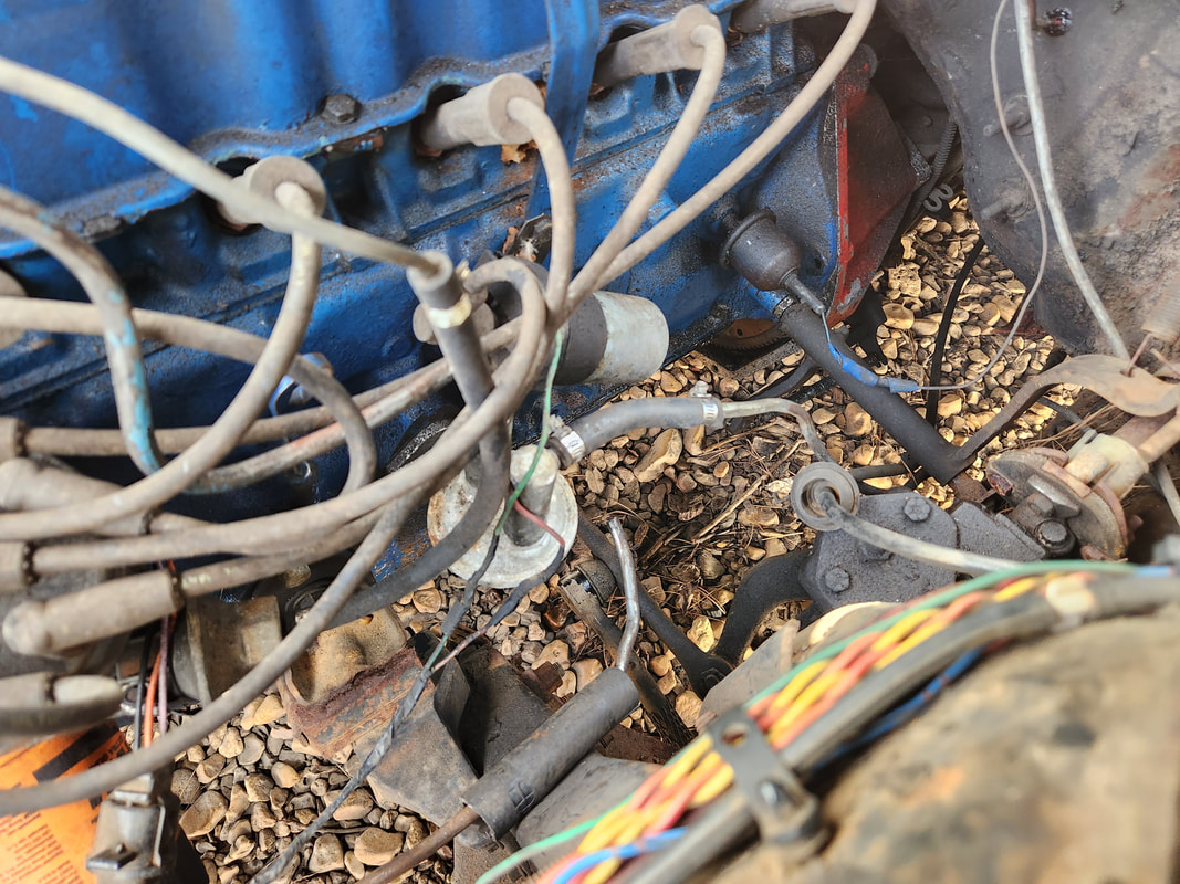
Along with the other routine maintenance that we've had to do on cars like the Scion, the Tracker finds itself not immune from the need for maintenance. Squealing brakes caused us to have to grab some brake pads to replace on the front, in order to see if attention will need to be turned to the rear brakes, if the squealing continues. This is fine as the vehicle is being used currently for delivery runs, due to the AC being down on the Scion and the temps starting to rise enough. Hopefully the replacement AC line will be arriving more sooner than later so that problem can be resolved. In the meantime, keeping up the other daily drivers is paramount. 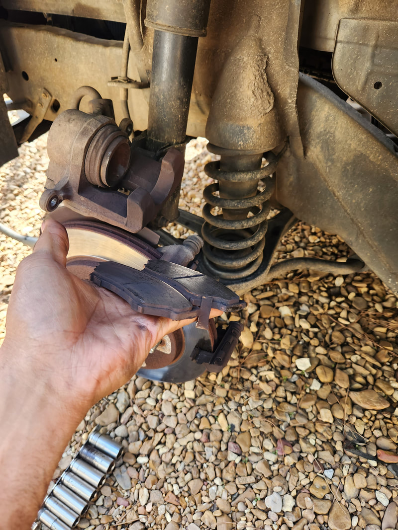 The front brakes on the Tracker were indeed at the point of hitting the squeal tabs, they needed replacing after all. On a lighter note, while I wait for the C4 transmission rebuild kit to arrive just as well, I took a moment to clean up the transmission body, as it was covered in 15 years of dirt and grime that needed to go. After a little bout with a parts washer, I managed to clean out the bellhousing pretty good, leaving only some small spots that I couldn't reach with any brush. The transmission body took a good deal of scrubbing just as well to get the body cleaned as best as possible, as well as the inside, especially where the pistons, which had grime inside the cylinders and on the piston assemblies, all from the disintegration of the clutch discs. The tail shaft didn't take a lot of effort to clean as there really wasn't a lot of action going on in this area, but it too is nice and clean. 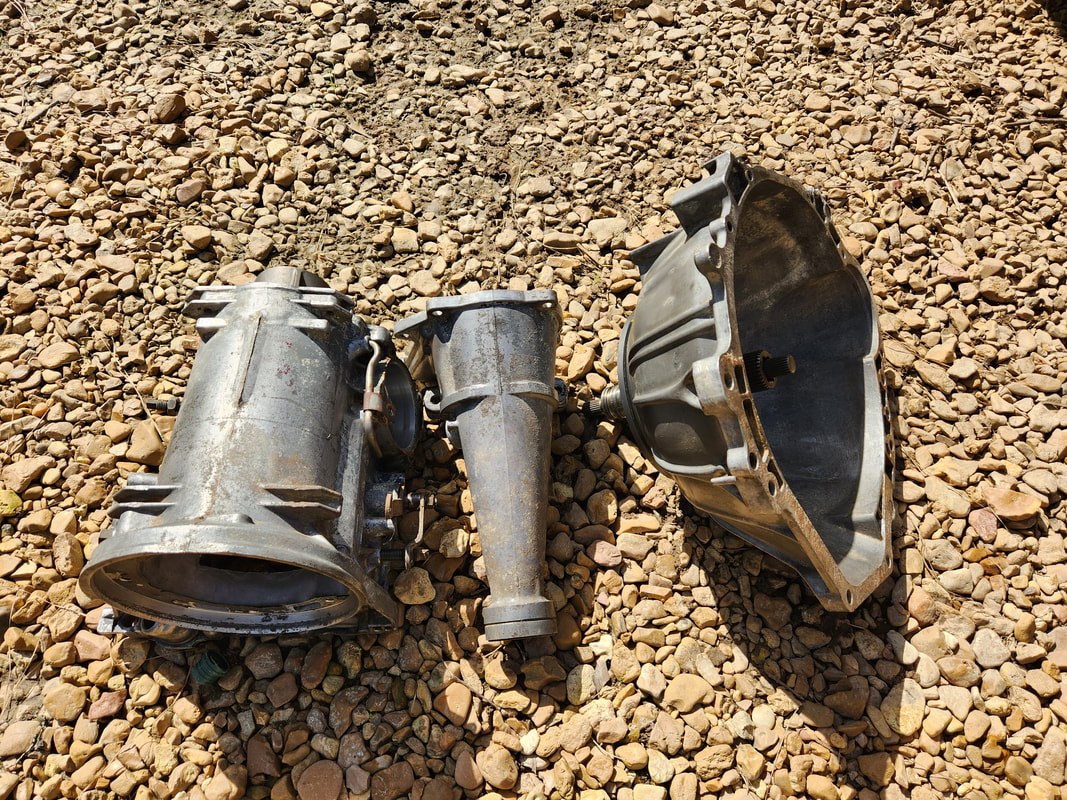 The C4 transmission body components after a thorough cleaning in a parts washer. After doing some thinking, I had decided that I really need to turn my attention back to the Elco. It's been a year since I last worked on the car and before I start another serious car project, I would really want to get this one closed out. I still have to finish Truckstang just the same. Once I get the C4 transmission reassembled and installed and running again, Truckstang should be ready to rock and roll and undergo road testing. While there will still be plenty of things to do on the car afterward, just the idea that the car has been brought to the state of being a running and driving car means that the base project is complete. Things like body work, rear end work or HVAC work are extras that don't factor in with trying to bring the car to an operational state. The same goes for the Elco, trying to get the car to the point of being a running and driving car, even if there's a lot of little things to do that would go towards the restoration aspect of the project, is the most important thing. 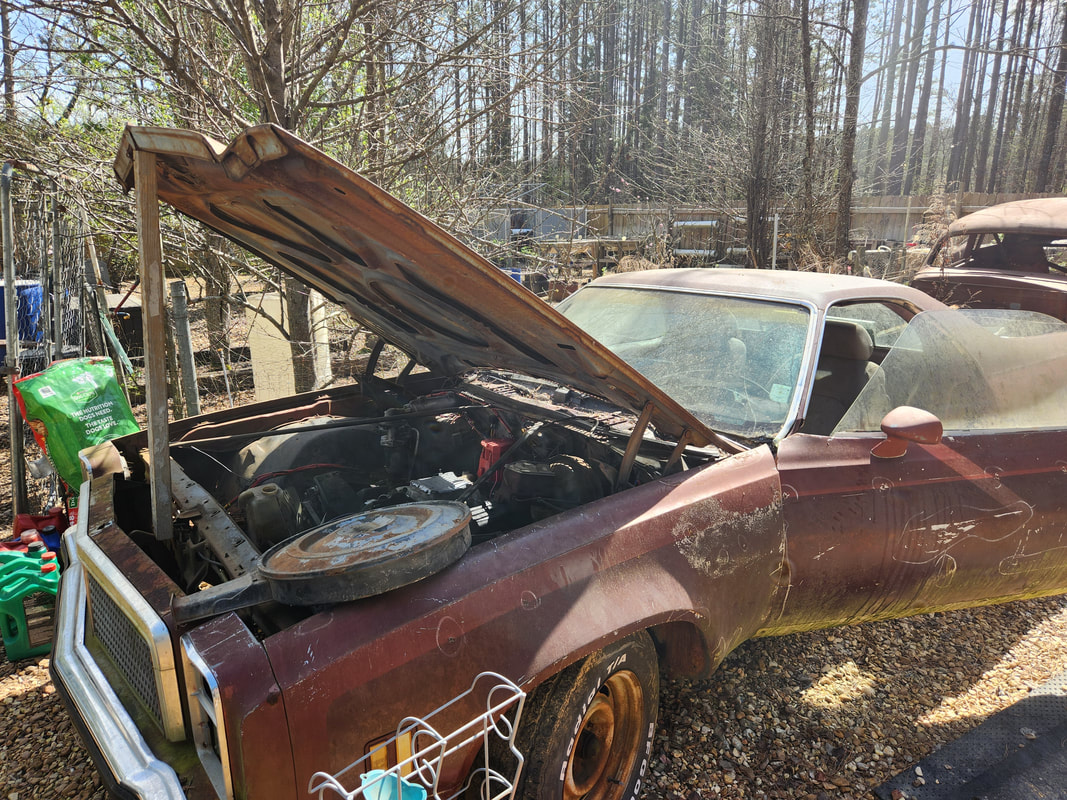 The Elco, coming back out of mothball status as far as project work. Here I took a moment to clean out the dirt and crap that gathered around the base of the hood and around the battery tray. One of the first areas on the Elco I want to turn my attention to is the engine. There's plenty that needs to be done to bring the engine, and the powertrain as a whole to the point of being a running setup. The engine needs plug wires, a carburetor, starter, hoses and other plumbing added, a radiator, exhaust, fuel and a battery. I need to add the adapter to the carburetor to hook up to the TV cable on the transmission, along with the shifter and oil lines from the transmission to the radiator. Of course, a driveshaft has to be sourced. 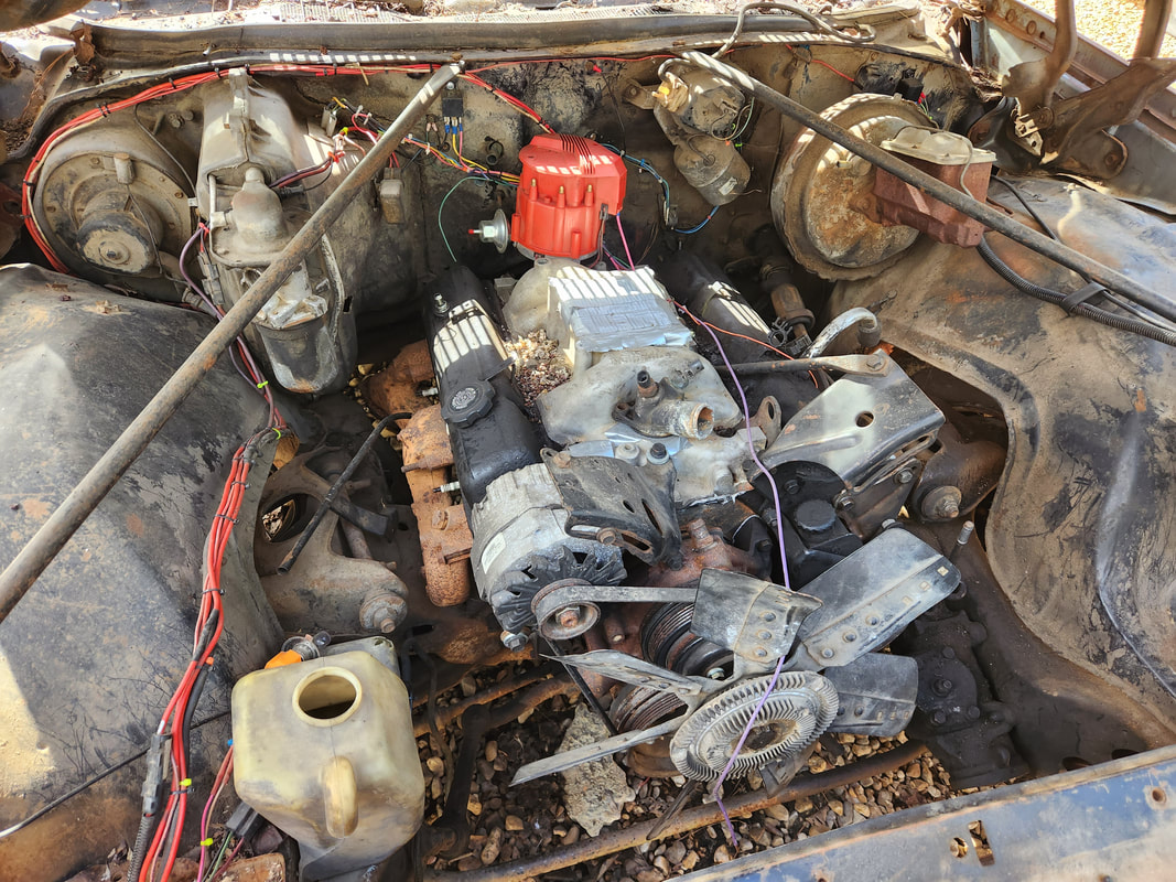 The Elco's engine bay, showing all the things that are missing on the engine. Many things will need to be sourced to get the engine to the state of being able to be started. What all this means is that I'll be having to start picking up batches of parts in the right order to allow me to make the biggest headway in each step. My first batch will be plug wires, a starter, thermostat and housing gasket, possibly rad hoses, and a radiator. My plan with the radiator is to measure the opening around the core support and see if I can source a radiator that can fit within that area that comes from another car/truck with a V8. I don't necessarily have to get a rad that fits this car, just one that will go in the opening. My next junkyard foray will have me trying to source a radiator, starter, and even the flange pipes from the exhaust system of an older V8 truck. Since the SBC exhaust manifolds used on most of the trucks are about the same, I should be able to find something that I can use on our exhaust manifolds, even if I end up having to weld the short length of flange pipe to each exhaust manifold. Point is, the Elco will be the next big project on the list to try and finish.
With the uniqueness of this project, the energy placed in getting thigs right is pretty high. Between the O2 sensor and gauge, the gallon fuel can test system and extra hose barbs, I've been doing a fair amount of work on this simple little project with even more work to come. One of the things I did do that only made sense was hook the main fuel line back up to the fuel pump since I wasn't ready to do MPG tests, so it didn't make sense keeping the gallon fuel can hooked up, requiring me to have to constantly add a gallon of fuel to the can. This was necessary as it would also point out any possible flaws with the gallon can fuel system just as well. I already had to hook the pressure regulator back up as my fuel bypass setup didn't pan out, so we're back to where we started as far as the fuel system. I did add the hose barb for the vacuum advance on the distributor as well, while leaving the hose barb open on the intake manifold in order to draw the air in necessary to get the AFR to an optimal point.
The main fuel line is hooked back up to the fuel pump since we're not doing MPG tests yet.
One of the other things that I took care of that I was late doing was advancing the timing on the distributor. Because of the physics behind this carburetor and the fuel mixture it administers to the engine, basically a smaller mixture, ignition would have to be sooner to allow the thinner fuel mixture to get completely ignited. By the time the cylinder reaches TDC, the fuel has reached a point of near complete combustion to push the piston down. This of course is exhibited in the higher RPM as the engine seems to get a jolt of power when the timing is advanced. Also based on the science behind this, better explained on the Thunderhead289 videos on this same project, vacuum advance is not really present due to how vacuum functions with this carburetor setup so advancing the dizzy more kind of helps on this angle just as well. 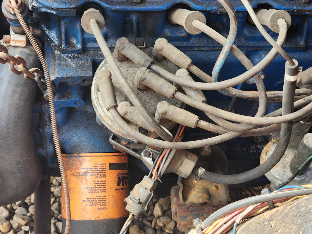
This engine still uses the old Duraspark ignition system, which I haven't bothered to change out as it still works fine. This time I had to advance the timing to coincide with the thinner fuel mixture.
I did do some driveway tests, driving the car up and down the driveway to see how the engine acts and how our AFR reacted. It would go rich during acceleration cycles, obviously, as the engine is sucking in more fuel, even in the absence of air, and upon deceleration, go super lean for a little while as fuel flow is restricted while the engine is throttling down, while still drawing a higher amount of air flow, resulting in the engine sucking every bit of fuel from the intake even after flow slowed from the carb. I would have to guess this is normal operation anyway, but it was interesting to note, just for reference when it comes to really learning how this fuel system works. 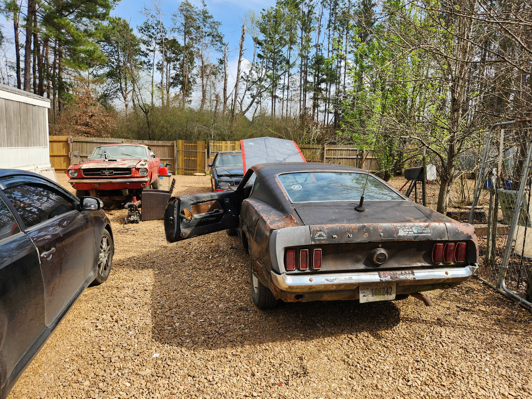
Rustang parked in a different spot after switching places with the Monte Carlo in order to test the car out.
Of course in order for me to do the driveway tests, I had to move the Monte Carlo around to the back parking spot where Rustang was situated earlier. Afterward, I started doing more tweaking to try and see how the AFR continued to react. One thing I noticed was that the AFR was bouncing around, sometimes going as rich as 10:1 and as lean as 15:1. I would imagine that the fuel pressure regulator as well as the carburetor's fuel flow contributed to the flaky AFR readings. If the fuel pressure gets a smidge high then extra fuel squirts out and makes the mixture rich, while a slight drop in fuel pressure has the opposite effect. At this point my main thing was to try to have the average AFR be somewhere around to the slightly rich side, as too much air can actually be worse for an engine than too much fuel. Too much air means too hot a burn and that means damage to the engine. Too much fuel will actually help in cooling the air charge and in turn, the engine internals, as gasoline has endothermic properties, absorbing heat from the environment. Up to a certain point of course, but then it gets to a point where the fuel undergoes incomplete combustion and carbon build up results, then more maintenance is required, but that's for another discussion. 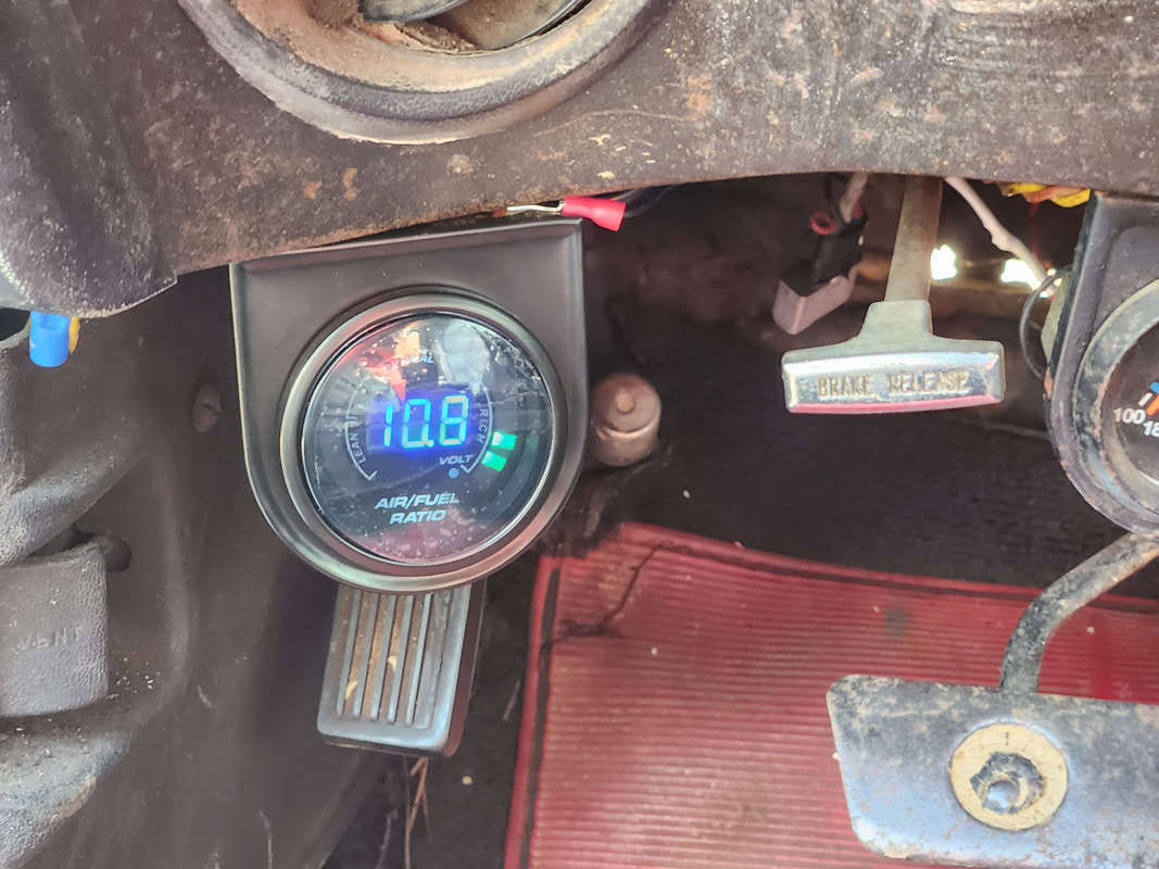
The AFR will drop as low as the 10:1 at times...
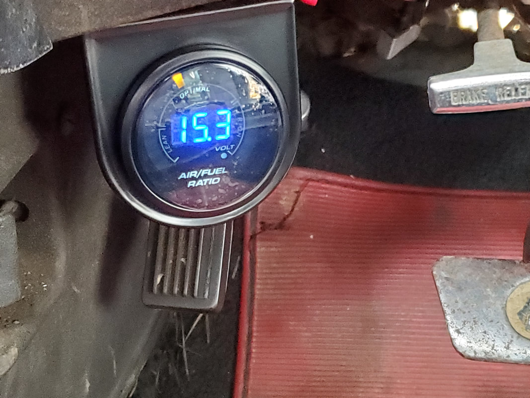
The AFR will bounce as high as 15:1 on some occasions.
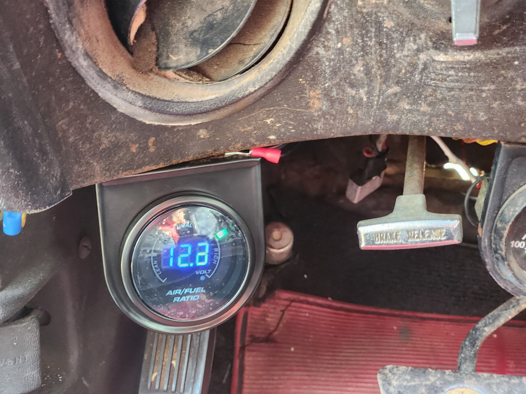
I chose to try and keep the AFR around a slightly rich condition as most carbureted engines are set up in this manner, for a couple reasons we won't bother to further discuss.
The next thing I wanted to do, in order to get ready for recording the work being done, was hang camera mounts on the car. I wanted to put a mount on the roof for an action cam to record clips from that angle of the car going down the road, and another camera mount on the inside, aimed forward through the front window while also looking slightly downward at the last camera mount which is really a mount for a phone. The phone will have the GPS speedometer app on it operating. The camera in the cab will see the numbers on the speedo app in real time while both cameras will see us in motion. For the sake of validity, I will also remove the camera in real time to show the carburetor still in operation during the driving, just to verify we're not trying to pull some slight of hand during this project. 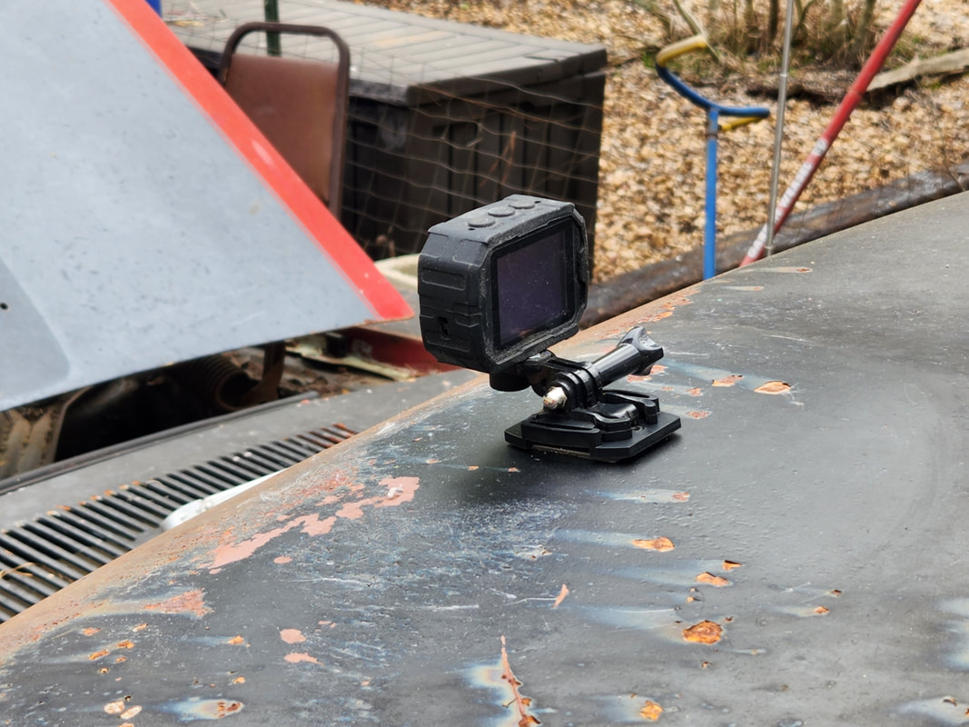
Camera mount stuck on the roof to hold action cam for recording shots from the perspective of riding on the roof.
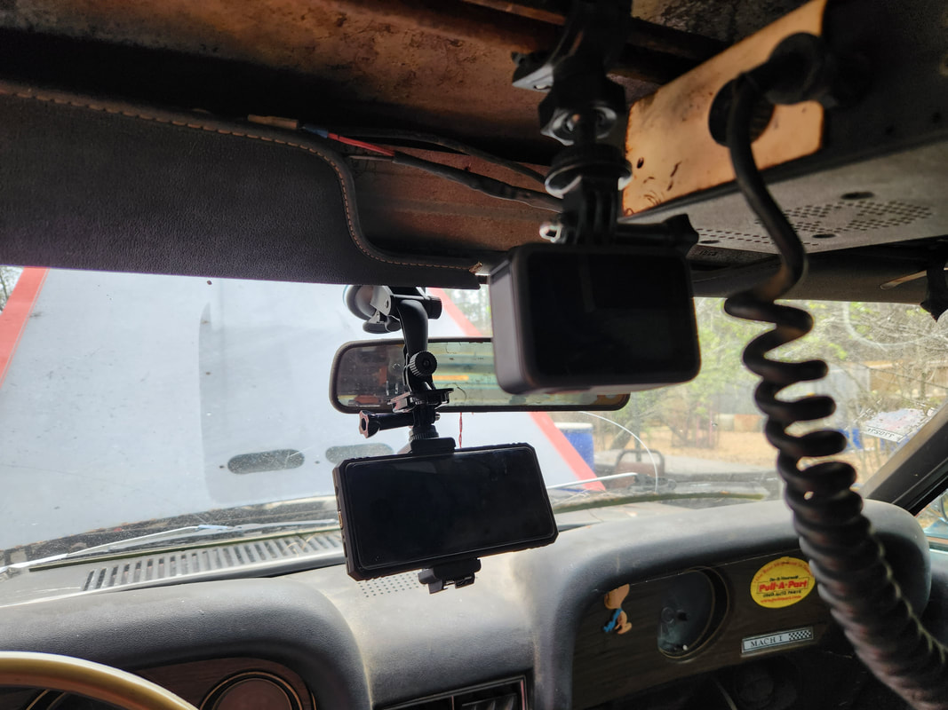
Gopro camera hung on mount from support bar I installed in the past to hold the CB radio that is currently in the car. This camera is aimed down at the phone mount that is also mounted in place on the window, just in front of and under the mirror.
The next video will really only briefly touch on the technical aspects of what we done, while mainly focusing on actual testing and results. We've already seen the engine run so we know the concept works for the most part, we want to be able to show proof of concept by actually driving the car with this system in order to show its validity as well as practicality when it comes to saving fuel while still being able to perform reasonably well. There will definitely be more to come on this unique project.
|
