|
In this session we have us a relatively boring day, compared to other days. There were things to do around the compound, from cleaning up crap to rearranging things and sorting through other things for future use, or disposal. Among all these things there is also some routine maintenance, especially on vehicles. This is especially the case on the Scion. Since the car is frequently used more in one day than the others are used in a week, it only makes sense that I'd have to fix crap on this car periodically. Even while waiting for a chance to get the replacement AC liquid line that was damaged, other things continue to need replacing, in this case, motor mounts. From the way it appears, the motor mount on the passenger side that holds what would be the front of the engine to the chassis had lost a couple bolts and was able to bounce around. This in turn caused the motor mount that attaches to the front of the chassis and holds the middle of the engine in place. This torquing of the engine I believe caused the AC hose to move in such a way that it chafed the hole in it that compromised the hose. Well, after replacing the bolts on the "right side" motor mount, I replaced the "front" motor mount, restoring the support of the engine.  The old front motor mount with the core completely broken out. 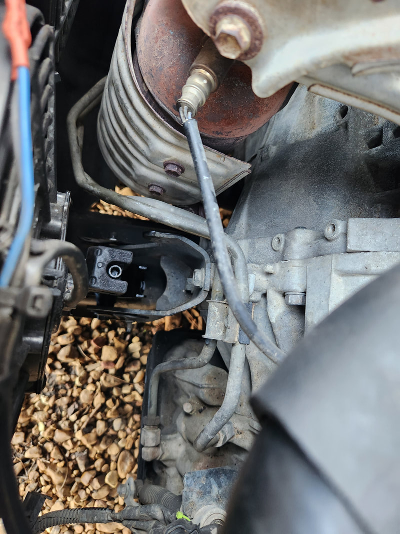 The new motor mount installed at the front of the engine bay while the other culprit motor mount was bolted back down. Along with this "boring" routine work, the gravel spreading never ceased. Currently, I'm trying to build up a wide path along the south fence line leading all the way to the east fence line. Unfortunately, this ground is very soft and mushy and in turn, requires a lot of gravel to even make it remotely stable for vehicular traffic. In fact, I would have to back the truck onto the gravel path and the areas where the tires mashed the gravel into the ground would have to be filled in with more gravel. The repeated driving over the already laid gravel and my refilling those areas is helping to establish the path enough so that hopefully there will be enough solid surface to allow me to just drive over without even thinking about it, like the rest of the areas within the fences. 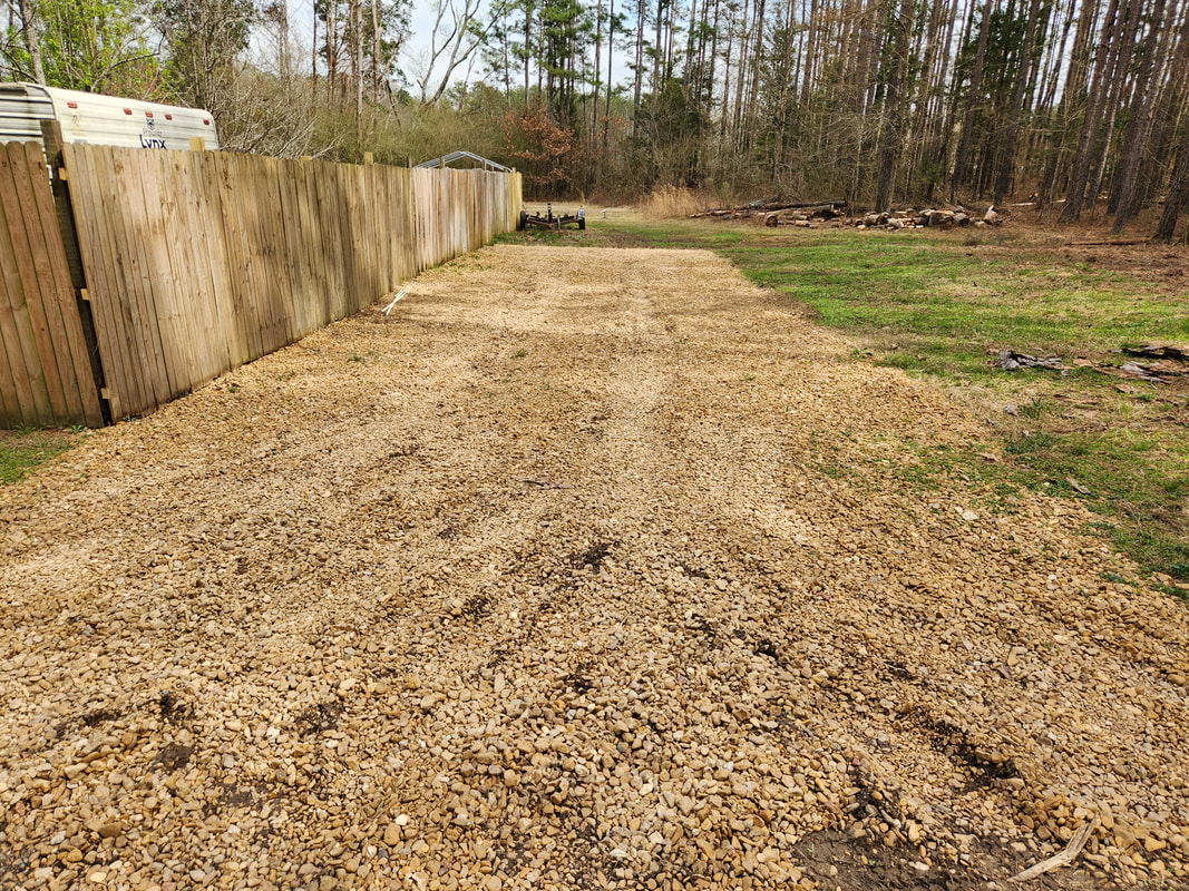 Shot from the main driveway down the gravel path showing the progress made in laying the gravel. Note the ruts made from the truck rolling over the soft areas and mashing gravel into the mud. 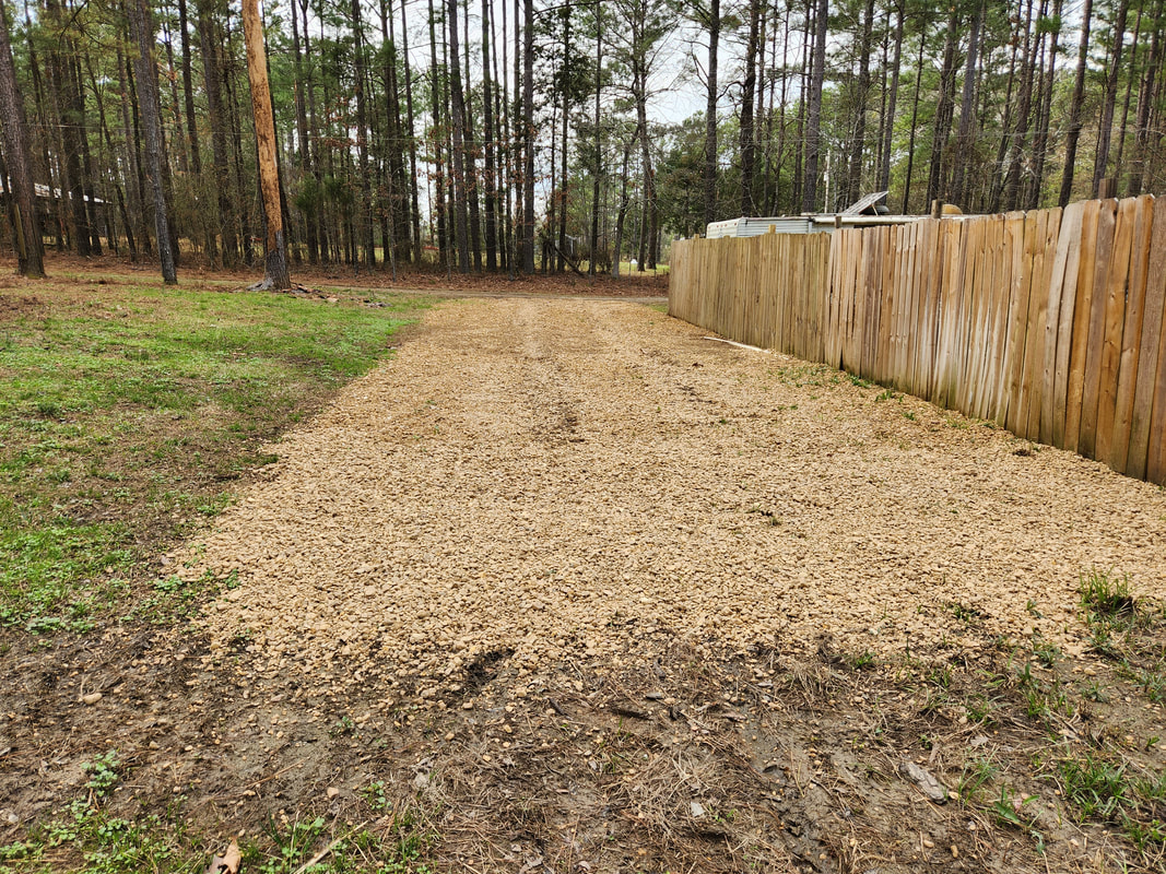 Shot from further down the path back towards the main drive. Because of the circumstances around the ground and the distance to be traveled along the fence line, we will be laying gravel along this area for the foreseeable future. Of course the end result will be well worth it as we will be able to move our rolling stock along the area to where we have them currently stored. When the ground does dry up we'll be able to move about even through the areas that don't have gravel. But as long as the ground remains soft, the gravel will be needed to ensure that we don't get stuck with whatever vehicle we use to retrieve our equipment from the east fence line.
0 Comments
Here's another one of those situations where we think we've gotten so far, but in reality we took a couple steps back. After everything that we went through to get the engine running, and actually getting the engine running, and running rather well, I moved on to see if we had motion. In the beginning we did get motion for a second, with the transmission going into reverse, moving, and going into forward gear and moving, with some crispness in fact. But then we started having problems where it seemed like the transmission was stuck in a forward gear. Even when the thing was in park it still felt like it was in gear trying to grab. I lost reverse and even didn't have neutral. At one point I did get it to work again, but quickly lost it, going right back to the all forward all the time mode. I checked the valve body to see if there was something that may have been wrong, but that wasn't where the problem was at. At this point I knew the transmission would have to come down. Luckily because of the truck frame build, it would be easier to pull the unit out, compared to the original setup where I would've had to pull the exhaust pipes along with everything else.
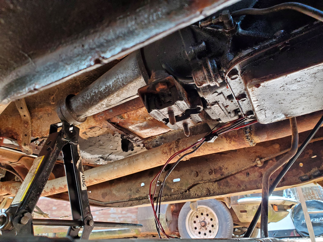
Jacking the rear of the transmission with a scissor jack to remove the crossmember to lower the transmission to the ground.
The first thing I had to do was remove the nuts from the torque converter. This was easy as I used the remote starter button to crank the engine around to expose the nuts to remove them. After that I pulled the starter free then pulled the driveshaft, draining as much oil as I could. I then put a jack under the transmission tail and removed the crossmember/mount, set up another jack with a board under the oil pan and pulled the bellhousing bolts. 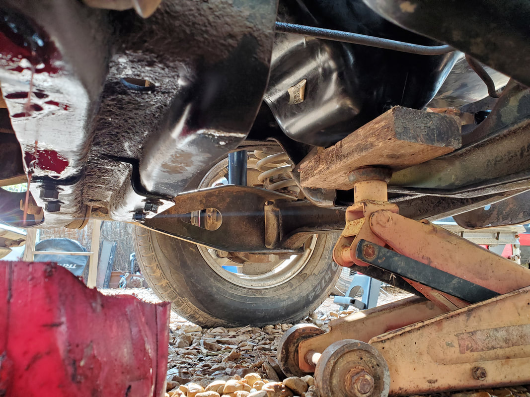
Positioning jacks under the transmission after removing the bellhousing bolts so I can somewhat safely pull the unit free from the back of the engine.
I was able to work the transmission free from the back of the engine and work it to the ground. Because of the height of the frame, I was able to slide the transmission to the rear to clear the higher point of the frame and exhaust pipes and pull it free. 
The transmission is free from the engine and from under the car, ready for disassembly.
I moved the transmission over to a better spot and set the thing on cardboard, then got to work. I pulled the bellhousing bolts free, removing the bellhousing and oil pump assembly. I loosened the band adjuster bolts and pulled the first drum out, which was the 2/3 drum and clutch pack. These appeared fine as the individual clutches were still free moving. I further pulled things apart, finally getting the reverse/1 drum and clutch pack free. There I found the problem. The clutches basically welded themselves together in the drum, with the material breaking free and binding the clutches and discs all together, causing the transmission to be stuck in 1st gear. 
The fried clutch pack discs in the reverse/1st drum. These were all stuck together, causing the transmission to be stuck in 1st gear.
I further pulled the rest of the planetary gears and other hardware apart at the rear of the transmission body to inspect everything and to just separate everything as I just wanted to be able to clean up the body at this point, since I'm more or less rebuilding the transmission anyway. All the other hardware looked good, with no other visible signs of damage. 
The transmission main body and drums with clutch packs and planetary gears, bands and more laid out after disassembly.

More parts of the transmission laid out, with the tail shaft body, bellhousing and oil pump, oil pan and valve body.
Even the bands for the drums were still in good shape, all part of the previous rebuild kit. All this means is I won't have to go all out and buy an all inclusive rebuild kit, just the basic kit that has the clutch pack pieces and other little bits, most of which I'll probably not even need as most of everything inside is still good. I'll clean up the transmission body and get all this internal garbage back together. While I'm at it I'll replace the dipstick tube so hopefully when I reassemble this thing it will finally run and run properly for the foreseeable future.
After making a bunch of different changes and updates to the mower carb setup, I was ready to run the setup again. I had added an O2 sensor bung and sensor, A/F gauge, hose barb for vacuum advance, fuel line return/bypass line, and a gallon fuel can for the sake of testing for MPG numbers. That will be done by driving on that gallon of fuel and seeing how many miles I can go before exhausting the gallon of fuel. That will be for a later date. Anyway, now it was time to see if this new setup will run, and in the process, tune the system to hopefully get it to run at its best, based on the A/F gauge. Our first problem experienced was right when I tried to start the engine up, and that problem was with our fuel line return/bypass.
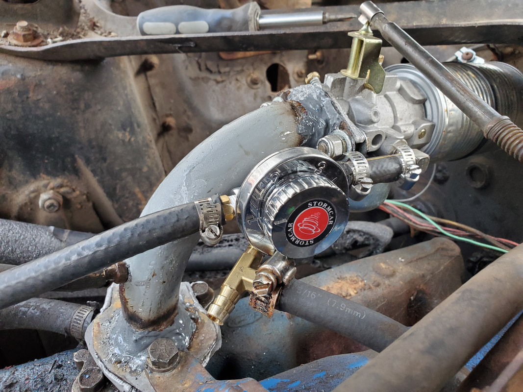
I had to add the old pressure regulator after the failure with the fuel line bypass setup.
Even though the fuel pump did its job of drawing fuel from the gallon fuel can, there was a simple problem. That problem was the idea the fuel pump already pumps at a relatively low pressure to begin with. Because of this low pressure, fuel was bypassing at the tee that was added well before pushing any fuel into the carburetor. No fuel was even getting into the carburetor, even with the help of starting spray. The fuel pressure and volume just wasn't there to help. I ended up having to install the pressure regulator all over again and removing the tee and bypass line. This idea may have worked if I had a fitting that applied a tee right at the carburetor where fuel would go right into the carburetor and then flow into the bypass line. In the end, we're pretty much going back to the regulator. If this unit proves to be a problem in the future then I may install a better quality unit. Anyway, once the regulator was back, the carb got its fuel and fired right up. After getting the engine at a reasonable idle, I started monitoring the A/F gauge. It was running at the far end of the rich scale. 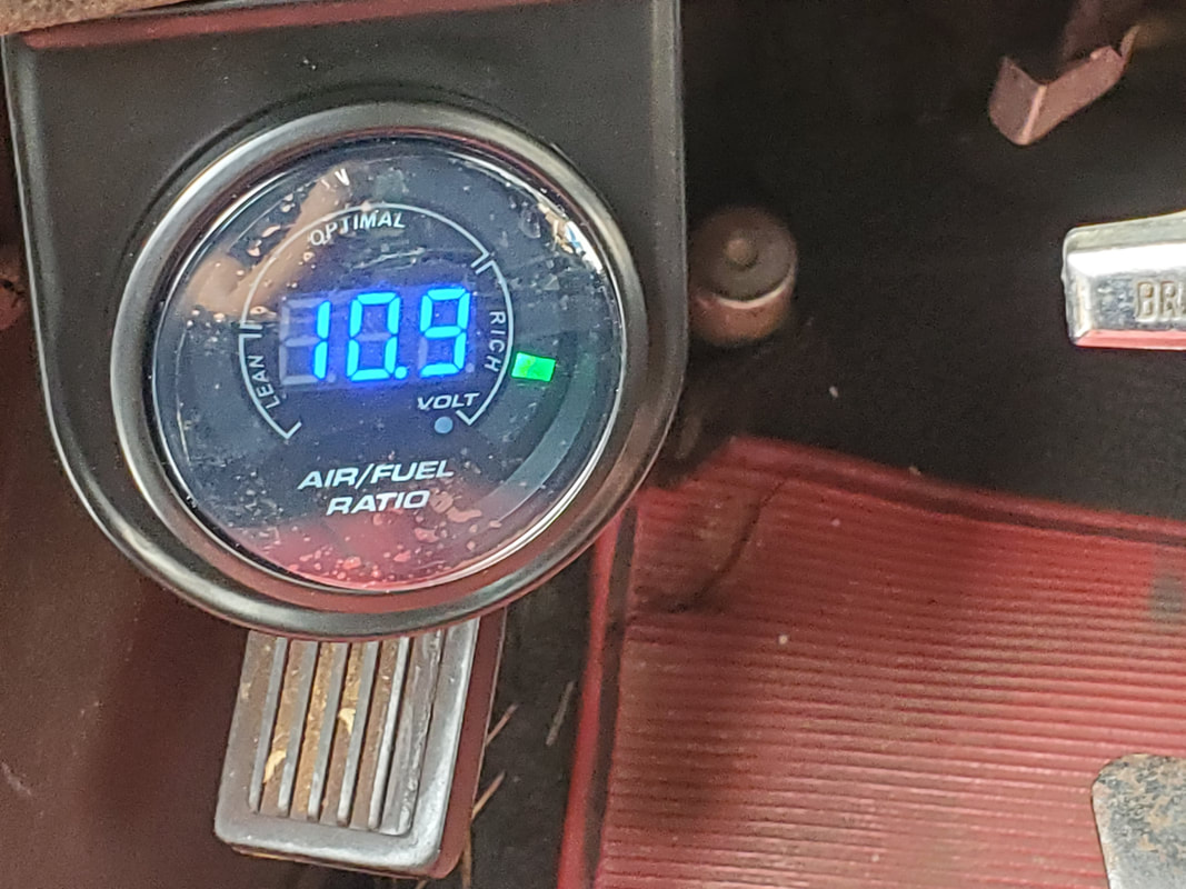
Before making adjustments, the engine was running at the far end of rich as seen here.
At this point I had to see what I could do to change the A/F ratio. Even though the engine sounded like it was running pretty good, it was clearly running rich. This was even with the hose barb left open on the intake manifold. The vacuum advance was working on its own hose barb but even with this air leak left open, it was still running rich. I started playing with a couple screws on the carburetor. I'm not sure what the second screw would be for, but I know one of them was for the A/F adjustment. Sure enough, I found which screw affected the A/F gauge. Even slight tweaks made the gauge change. Eventually I got the gauge to read in the optimum range, floating between 13:1 to 15:1. Perfect would've been 14:1, but this range is optimum for what would be considered proper operation. With the engine running at operating temperature, I made very small tweaks until I was able to get it to stay as close to 14:1 as possible. 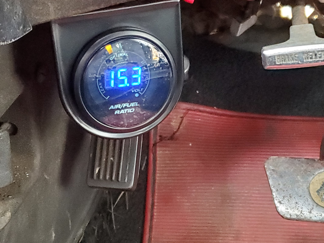
After making adjustments on the carburetor, I got the A/F ratio to the low 15's. I had to dial it back as the engine started not sounding too happy. I dialed it back to around 13 to make the engine happy again.
I made one more tweak until I had the gauge reading around 13:1, which the engine seemed happier with. When the gauge was reading in the 15 range it seemed almost like it was starting to starve for fuel. Putting it closer to the richer side of optimum made the engine happy. At this point I left the engine running to see how long it would run on the gallon of fuel. The total of time that the engine was running from when I first started all the way up to where it finally sputtered out, was probably around 90 minutes, which sounds good, as this may mean the engine may yield a good MPG number when I do test it. That will be the next big thing. I will do some pre-tests by driving the car up and down the driveway just to get a feel for the system and after that I'll stage myself at the road, top off the fuel can, set up my speedometer/odometer app on the phone along with cameras then start the testing.
This is how it sometimes goes with these types of projects. When one thinks they've gotten so far ahead, they end up getting roadblocked by one thing that can end up being something critical. In our case, we have two issues with the transmission. The first problem is the dipstick tube, which has a leak right at the base. After pulling the tube out, I found that along with the worn rubber O-ring, there was a small split right where the O-ring sits. This pretty much meant that this thing would leak no matter what. I even tried a vain attempt to make a seal by wrapping electrical tape around the groove for the O-ring then putting the piece back in. This worked for a short while, but I can imagine the heat of the transmission probably compromised the tape enough to make the tube start leaking all over again. All this means at this rate is I will have to replace the dipstick tube. While this is a setback, it's not a critical setback, as a replacement tube can be had online for fairly cheap. I would just have to wait for it while keeping a pan under the transmission to catch leaking oil. 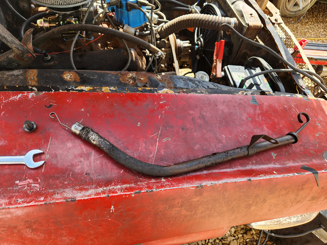 This old distorted and beat up dipstick tube removed from the transmission will need replacing as its too compromised at this point. It does nothing but leak excessively. 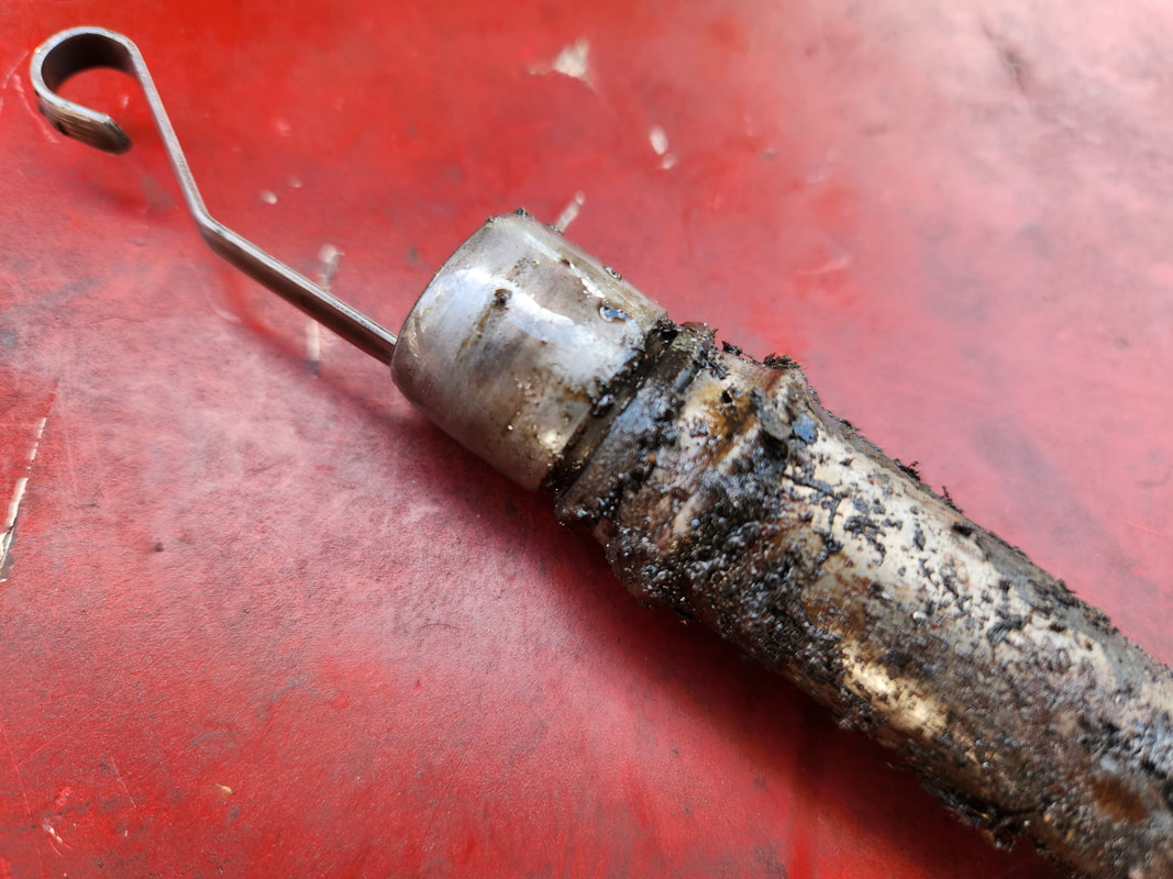 The base of the oil dipstick showing how worn the O-ring was and how distorted the metal around this portion of the tube is. The next more critical problem has to do with the operation of the transmission. After a couple tests with cycling the shifter on the transmission and actually getting the thing to jump into reverse as well as a forward gear, I started having problems where it seemed like the transmission was stuck in a forward gear, with no reverse. The first time I experienced this I was able to get reverse back again, but this next go around, I wasn't able to. I got reverse in the very beginning but lost it pretty fast. No matter what I tried, the transmission was stuck in a forward gear. Even in park, the transmission felt engaged, until the parking pawl latched, but it was still under load. I didn't even have neutral. After doing some quick research, I adjusted the bands and tried again with no change in operation. I then decided the next move would be to pull the pan and look at the valve body and the band adjustment screws to see if there is something that sticks out like a sore thumb. 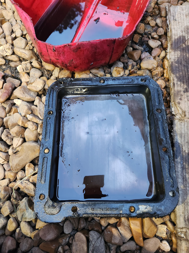 The oil pan after pulling from the transmission. Luckily the gasket remained intact. The amount of metal shavings in the pan wasn't too rediculous. There was some metal filings in the pan after removing it, but this is usually normal to have some metal as the transmission grinds itself during normal use. Of course, even with this thing being a rebuild, the amount of filings in the pan was not too excessive. So, moving on from that, I pulled the valve body. I had to work the selector valve, I believe it's called, to ensure it functions and isn't stuck. I did find the intermediate band was tight, even after making adjustments beforehand. With the valve body out, I was able to verify that the band adjusted properly. 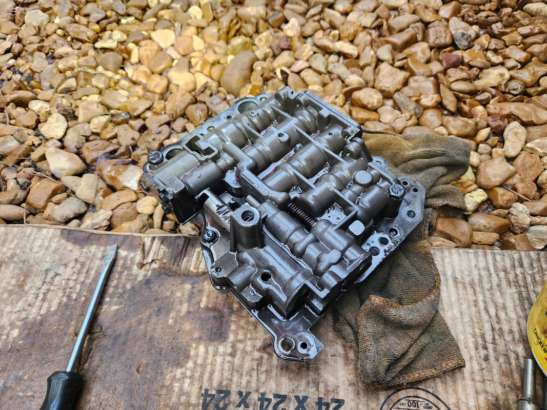 The valve body pulled from the transmission for inspection to see if anything may have been "wrong". 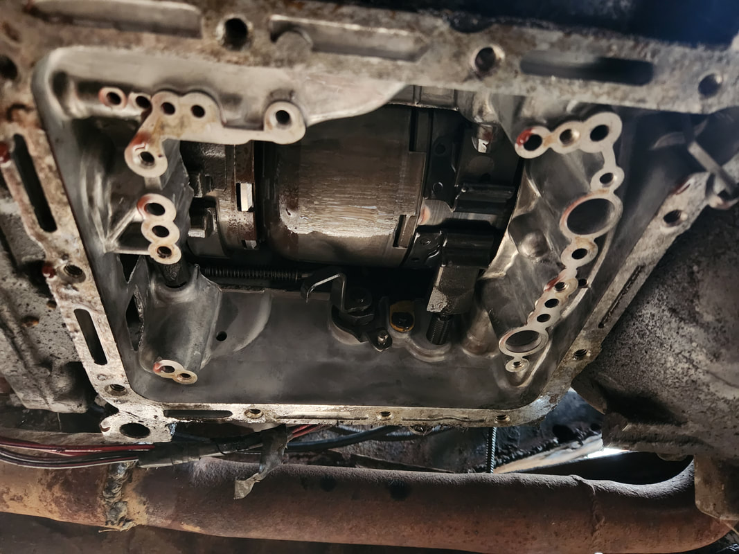 The open area in the transmission after removing the valve body, exposing the drums and the ends of the bands that engage the drums. The proper adjustments were made on these bands with the transmission opened up to verify everything was good. After looking at the things previously mentioned, I reassembled everything, hopefully this stupid transmission will start working again. Research on people who had the same exact problem quoted everything from a problem with the valve body linkage not being engaged to the clutch packs being welded together and causing the transmission to be stuck in a particular gear. I'm obviously hoping that I won't have to pull this POS and disassemble it again to see what's up inside and in no lesser terms damn near rebuild the thing again. It's not like it'll be hard to pull the unit out given the fact that the area is wider open than in the original car, but pulling transmissions still suck. After the initial tests with the lawn mower carb setup on Rustang, I had already determined several things I had to do. One of the things that I had left to to was add a hose barb fitting to accommodate the vacuum advance hose from the distributor. I had the hose already plugged up to a barb on the stock intake manifold, but I would need this fitting open for the possible metered air leak I'll have to set up in my attempt to make this whole fuel system operate at a proper fuel/air ratio. In order to put a hose barb fitting on the mower carb intake plenum I would have to remove the assembly, as drilling through the tube will throw metal shavings into the stock intake, which we can't have. Removing the assembly would require me to make and apply a new gasket as the old one will be destroyed upon the removal of the intake assembly.  A liberal amount of JB Weld was applied to the weld slag around the base to cover up the small pits and pinholes that were still present after welding the two pieces of metal together. Covering this up will ensure that no other air leaks will be present that will throw off the operation of the whole fuel system.  Hole drilled in intake plenum for the hose barb. I drilled a hole through the curved tube then used a 1/8 NPT thread tap to cut the light thread in the hole. I used teflon tape on the fitting and snugged the hose barb fitting in place. I also wanted to take care of another little problem that was still present from the first test of the mower carb setup.  Using a 1/8 NPT thread tap to cut the light thread in the hole after drilling it out. Note the JB Weld smeared all over the weld slag on the base. When I ran the engine before with this setup, I noticed some moisture around the welds at the base of the intake plenum. I kind of figured that there were pinholes in the welds I did with the curved tube and the base. Rather than risk burning up this assembly trying to fill in pinholes with more weld slag, I just mixed up some JB Weld, using this to cover the whole weld area around both bases on the curved tube. Covering all of the weld slag would ensure that any pinholes present would be covered thoroughly. With this, the whole carb/intake assembly is ready for reinstallation.  The intake plenum with the hose barb secured in place, along with the JB Weld smeared all over the weld slag. Note the bits of metal filings in the epoxy, which were from the drilled out hole. I smeared a bunch of gasket maker over the inside of the intake base and applied the gasket, then smeared a bunch more gasket maker over the gasket. Since the base isn't a machined smooth surface, I would have to compensate by applying enough gasket maker to ensure that any gaps present when the intake assembly is bolted down are filled in. 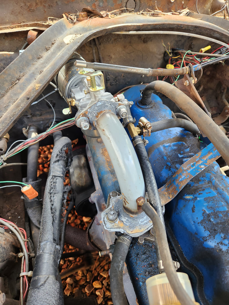 The modified mower carb/intake assembly after covering with JB Weld and adding the hose barb. It's bolted down awaiting the epoxy's curing. With the carb/intake assembly bolted down, all I have to do is wait for the JB Weld to cure. The choke cable and other hook ups are all taken care of, so once the epoxy is dry, I can go ahead and get things set up to start the engine up again, running off the makeshift modified fuel system. I will get to see how the bypass setup will work to determine if this is a viable setup or if I need to go back to the little pressure regulator arrangement. I will also get to see what I may have to do regarding the air leak with the hose barb, whether it being wide open will give us the air/fuel ratio we need or if I have to fabricate some kind of valve that will open and close based on engine vacuum, which may then have to be tapped into the same air line as the vacuum advance line. Only time will tell.
Now that Truckstang is running and running good, I can focus on the other little things that needed attention that at first really weren't high priority things. One of those things was the fact that the charging system did not appear to be doing its job. Now, the voltage regulator that's on the car looks to quite possibly be the original unit, maybe, maybe not, but it is the fat bodied unit that was common on the middle 60's cars when they transitioned over to alternators versus regular generators. This unit of course has its level of surface rust that helps to show its age, but its true age is unknown.
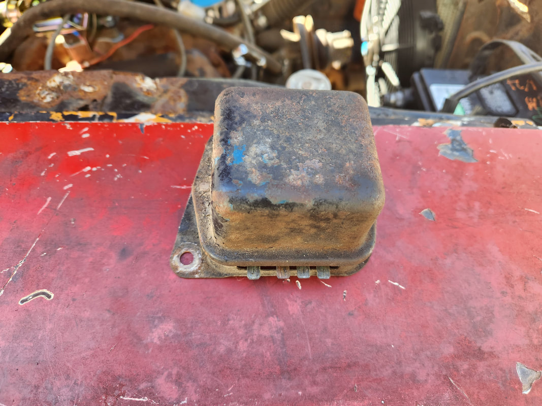
The old style voltage regulator that was originally on this car since the first time I began working on it, and that was over 20 years ago.
Luckily, I still had several new style slim voltage regulators in stock, leftovers from the time when I was running that charging system in Rustang. I've long since upgraded to a 3G alternator, with its onboard regulator, which only requires a couple wires, the switched power that supplies the regulator and in turn the field and stator coils, and the power output wire that hooks up to the battery. I may do this upgrade in the future on Truckstang just to further neaten things up, but right now, if it ain't broke, don't fix it. We'll continue to roll with this old system until circumstances tell me its time to switch over. Anyway, a new regulator and a double check on the wiring to confirm where my hookups go had me ready to rock and roll. 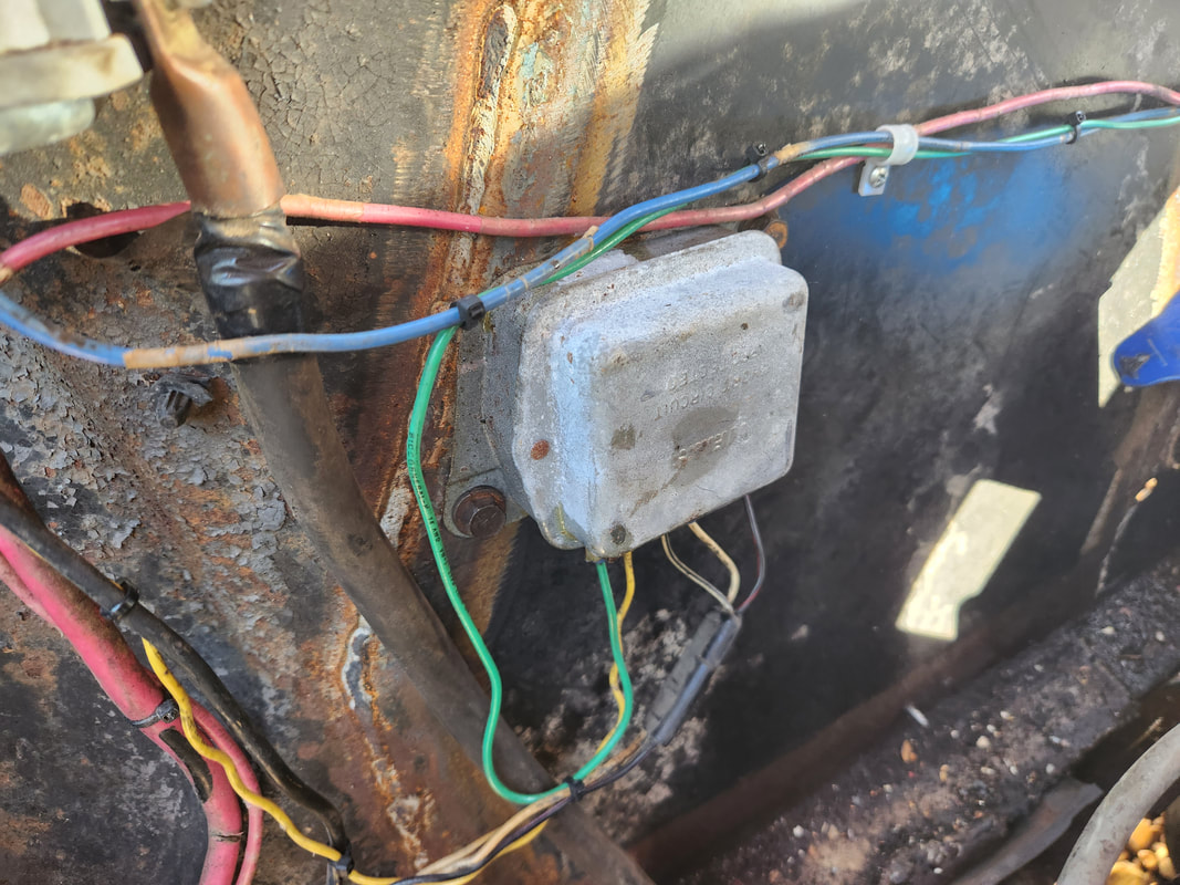
The new style slim voltage regulator mounted in place and hooked up while the engine's running during its break in period.
I already knew the system started charging, as soon as I hooked up the wires to the new regulator, the engine RPM made a noticeable change as the load of the alternator came into play. I double checked by pulling the positive battery terminal from the battery, an old school method of checking for a functioning charging system. The engine continued to run, fed by 12v power from the alternator. With that, I was satisfied Truckstang's charging system was good to go. I let the engine continue to run for about a straight hour, all the part of the break in procedure that this new engine needed but never received before going into mothballs. In the meantime, I topped off the transmission, and had to play around with it for a bit as it was doing some weird crap where it seemed like even in reverse the drum bands were staying engaged. After some more playing around it finally started working where I had reverse as I was supposed to. As with the engine, even the newly rebuilt transmission needs a break in period as well. Another thing that I did notice was the transmission was leaking a very small but noticeable leak from around the right front side of the oil pan. After a close inspection, this turned out to be the dipstick tube leaking. This means I'll have to pull the tube, which will require pulling a bellhousing bolt, then clean the area and somehow reseal the area where the tube is inserted into the transmission body so hopefully it'll stay sealed. I can't have oil steadily leaking out, especially during road tests where I might lose transmission function while in the middle of the road. Compared to the previous problems with getting the engine running, this is a minor problem. Another thing I turned my attention to while letting Truckstang run was the lawn mower carb project. I left off with getting the O2 sensor arrangement all done, minus the actual O2 sensor. After a past visit to the junkyard, I sourced a regular O2 sensor that ended up being a 4 wire unit. Unlike the 1 wire unit that is just a sensor line, with the ground being in the sensor itself, this one has two wires for the sensor and its ground, and two wires for a heater and its ground. The heater is to just heat the sensor up so the host car's ECU can more sooner go into closed loop operation for fuel economy purposes. Of course none of that matters to us, we just need the sensor line. In this case I clipped the wires for the heater and used a simple two conductor terminal pair to plug the sensor and its ground to on the O2 sensor. On the other side I plugged the single senor wire to the other plug and added a length of wire to serve as a ground, routed through the wire bundle passing by and up to a point where I was close to a screw in the firewall, currently used to hold a bracket that holds the choke cable for the mower carb. With that all done, the O2 sensor circuit is all ready to rock and roll. 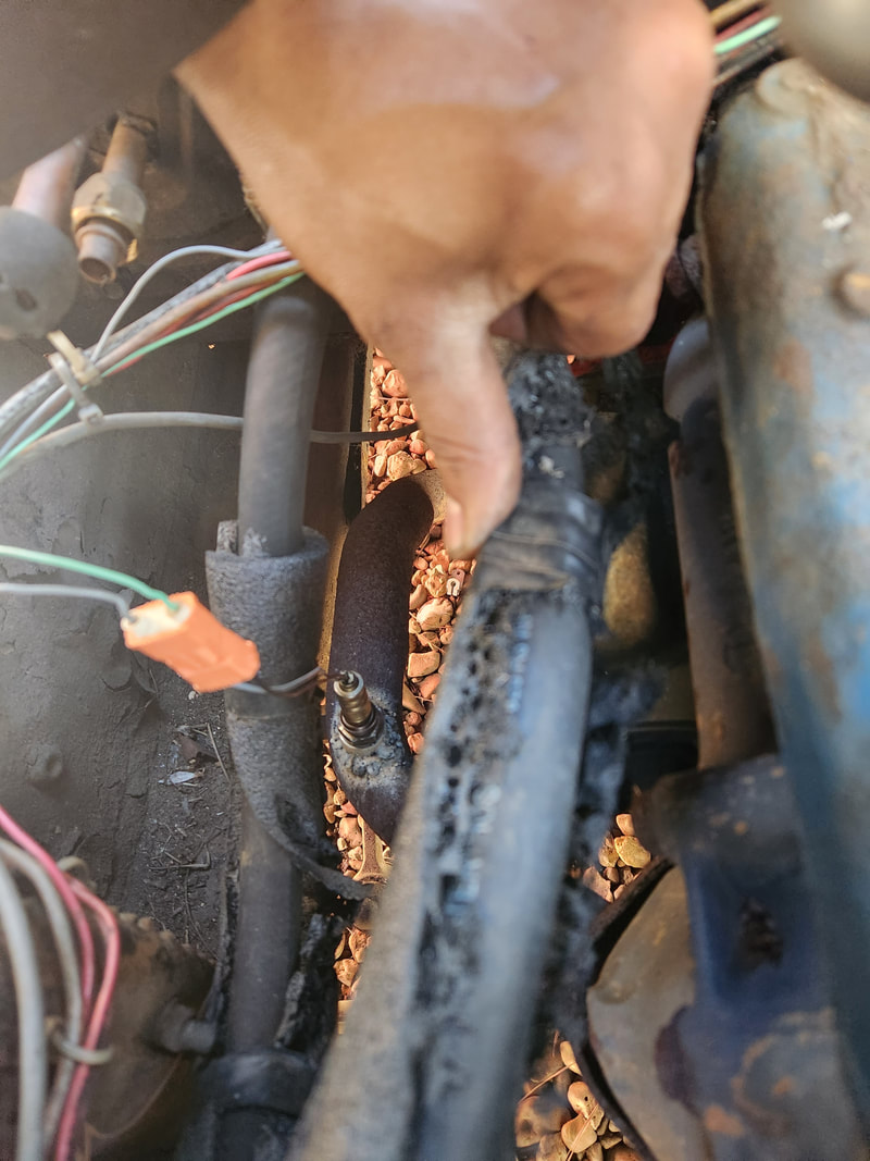
The junkyard O2 sensor in place on the exhaust pipe, along with the pair of sensor wires, hooked up to the two-piece plug connecting the car side of the circuit.
Another thing that I needed to do on this setup is add a nipple to connect the vacuum diaphragm from the distributor. This will be needed so the vac advance function will be maintained, even on this oddball setup. To do this I'll need to remove the mower carb intake plenum I made and drill a hole in the unit to thread in a hose barb fitting to plug the vac advance hose to. Simple thing, but to save from ingesting metal shavings, the intake has to be removed prior to drilling. Of course this will mean making a new gasket since the old one, having been glued down, will be destroyed upon the intake's removal. 
The mower carb intake and carb assembly removed, along with the hose barb fitting that will be threaded into the intake plenum to serve the vacuum advance on the distributor.
Once this is done, I'll also have the nipple on the intake free that can then be used for trying to adjust the amount of air being allowed into the intake during the engine's operation. As noted before, with this mower carb setup, the engine is actually running rich, given the fact that the air flow is restricted with the small intake. This nipple, whether open or hooked up to some kind of regulating apparatus, will help in regulating the air/fuel mixture to get stoichiometric ratio on the incoming air/fuel mixture. That's where the O2 sensor comes in. Once step at a time, our next step will then be to run the system and try to dial in things, then do some road tests. Somewhere in between I might figure out some kind of simple regulating apparatus for this air leak we need to maintain to make this system run at peak efficiency. More to come on all this stuff.
With the new HEI distributor in place, I made another attempt to try and start the engine. This time I was successful after getting the timing set good enough and administering enough fuel for the engine to pop off. Once the engine fired to life, I gave it a couple minutes and noticed that the lifters started clacking. The obvious problem was there was no oil pressure. I pulled the valve covers and ran the engine again with no oil coming up to the valve train. At this point this meant I'll probably be going inside the engine, but not quite what one may think. 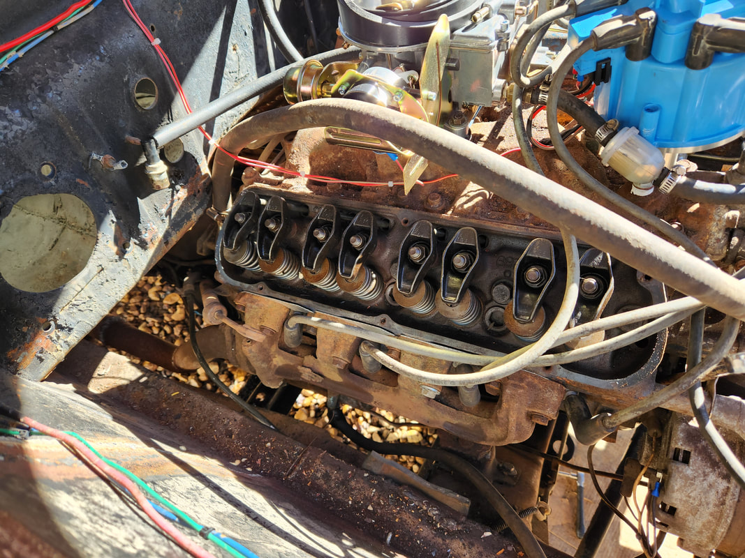 The valve covers were pulled in order to check for oil pressure during the first running attempt. First thing I did was pull the distributor and check for the seating of the oil pump driveshaft. After some playing around with a magnetic retrieval stick I got the shaft seated back in the oil pump and seated the distributor back onto everything. After another attempt to run the engine there was still no oil. At this point I would have to pull the oil pan to check everything. I pulled the pan and was able to drop it enough to be able to reach the oil pump. Luckily since I used a one piece gasket, I wouldn't have to pull the pan all the way out to clean the surfaces to reseat a four piece gasket set. I pulled the oil pump, which required me to separate the oil pickup since the rear sump pickup had a mounting bracket that held it to a main bearing cap bolt and removing this was not really an option I wanted to do. 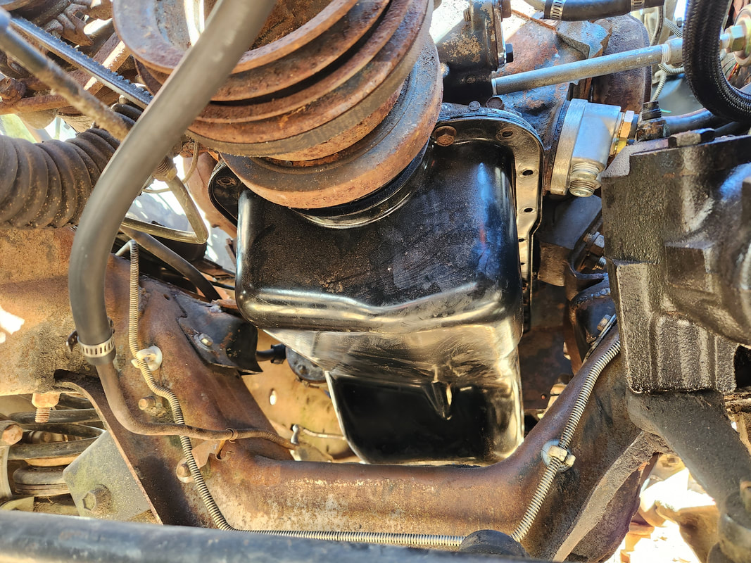 The placement of the engine on the truck frame allows for enough clearance to drop the oil pan enough to get inside the engine. With the oil pump off I pulled the pump driveshaft and hooked it up to the pump and hooked my small impact driver to the shaft. I stuck the input side of the oil pump in some oil that I had in the pan and cranked the pump just a little, sending oil three feet across the yard. That meant the oil pump was more than fine. With that, I turned my attention back to the driveshaft. After reseating the pump and driveshaft, I did a quick check. The shaft apparently had some play where it could slide up into the distributor shaft enough that it could come out of the oil pump's shaft seat. My theory was that during operation the shaft could come up out of the pump during rotation and not even turn the pump at all. As bootleg as this sounds, I stuck some tape into the distributor shaft and was able to stick the driveshaft in without it going all the way where it could slip out of the oil pump. Now, at this point the driveshaft problem was solved, if it was ever a problem. 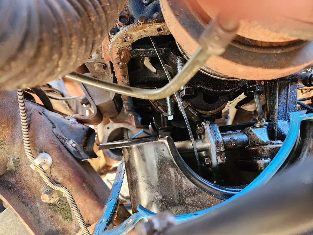 With the oil pan down, I was able to reach the oil pump to remove it in order to check its functionality. The next area I focused on was the remote oil pump assembly. What I looked at was the idea that the output hose on the base was plugged up to the output side on the oil filter base. If there's any kind of one way or check valve type thing on the oil filter or what not, then this hookup would obviously be held up at that point. Well, I corrected that problem and got everything back together. After resetting the distributor and wiring firing order, I went ahead and cranked the engine again and got it started. It only took about 10 seconds and I started getting oil coming up from the rear rocker arms on the right side. I had to put the valve cover back on for the other side in order to add oil so I could only look at the right side. Oil started coming out and before I knew it, oil was spurting out like crazy. A little while later all the rockers were shooting out oil. The engine noise quieted down just as well. 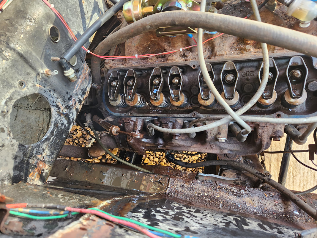 The huge oil spill mess after running the engine to verify oil pressure was present. After a short while I had to shut the engine down and put the valve cover back on as I was making a horrible mess. Afterward I fired the engine back up again and let it run, setting the idle. Oil pressure when it started cold was 40 psi. Once it warmed up it was around 20 psi, then when I set the idle down to 600 rpm give or take, it dropped to around 10-15 psi. Pressure would immediately jump up with RPM. Even after running for around 30 minutes, the temperature couldn't even be near hot as the radiator didn't even vent out of the release cap. Everything was warm but not hot. The temp gauge unfortunately did not respond so there may be a good possibility that its dead. If that's the case then it'll look like I'll be adding another gauge under the dash, which at this point, I really don't care, the engine is up and running. 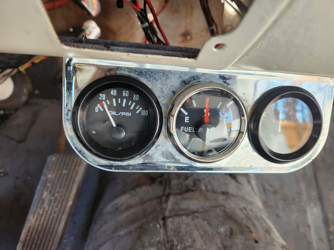 With the engine at idle, oil pressure is around 15 psi, voltage is only 12v, so I will have to check to see if the alternator or regulator are working, and we still have approximately 1/2 to 1/3 tank, based on what I put in the tank. I added transmission oil to the transmission and got it up enough that I was able to throw the thing into reverse and get it to spin the tire off the gravel. It was still low even then. It went into forward gear just fine as well. After topping the oil off in the transmission, I'm sure the thing will grab nice and firm. I rebuilt the transmission as well as the engine, neither unit really has any time on them, but they both sat for 15+ years. At this point I just have some mopping up to do to get the car ready for some more moving around from its resting point. I have to make sure the transmission is topped off, tires are aired up, plenty of fuel is in the tank, and more than likely add a temperature gauge so I can monitor that while trying any test driving. I do still have to make sure the driveshaft is straight as well, in order to complete that little side project. To do that I'll have to do some serious setting up to make sure the wheels are off the ground, and everything is sturdy as I'd be running the engine in gear to check for balance. We are indeed very close but still have some things to before we can really place ourselves in a place of experiencing completion with this project.
After a couple failed attempts to start the engine on Truckstang, mainly caused by the idea that I was having troubles with the old Duraspark ignition system, I decided to just dive in and buy another HEI distributor, same as what I used on the FMT. This simple setup, one of the things I can credit GM for producing, eliminates the cluttered ignition system that incorporates the distributor, an external coil, a ballast resistor, and rather large ignition module. All this is contained inside the distributor itself, making for a compact and neat setup that would clean up the engine bay.
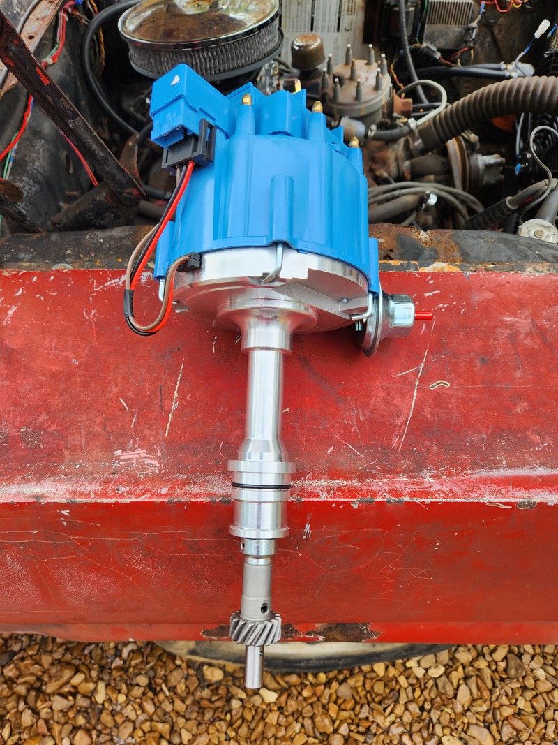
The new HEI distributor, ready for installation.
Of course the first thing that I had to do was remove everything from the old ignition system. Obviously this didn't take much effort, even less than what it took to put it in. I cleaned up a few of the wires involved as well. Afterward I would have to set the distributor in place, making note of where the rotor was pointing since that would be where TDC for #1 cylinder is. 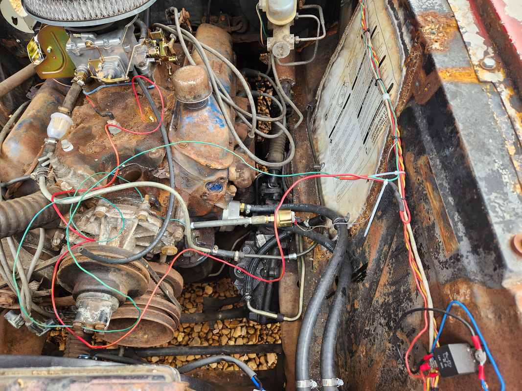
Left side of the engine bay after removing the old Duraspark system.
I ended up having to pull the oil pump driveshaft using a magnet stick then anchoring it in the distributor shaft before inserting the whole unit into the top of the engine. I was having the worst problem getting the distributor to sit due to the driveshaft not sitting itself right for the distributor to just slide onto the piece. With the distributor down, I was able to set the wires in place as well as get an extension to the power wire that was unplugged from the ballast resistor on the left panel. I cut the female terminal from the wire end and soldered another length of wire to this end, with another female terminal on to plug to the battery terminal on the distributor cap. I also added a length of wire to the wire feeding the tachometer, plugging it to the tach terminal on the distributor cap. Zip ties secured and neatened the couple simple wires. 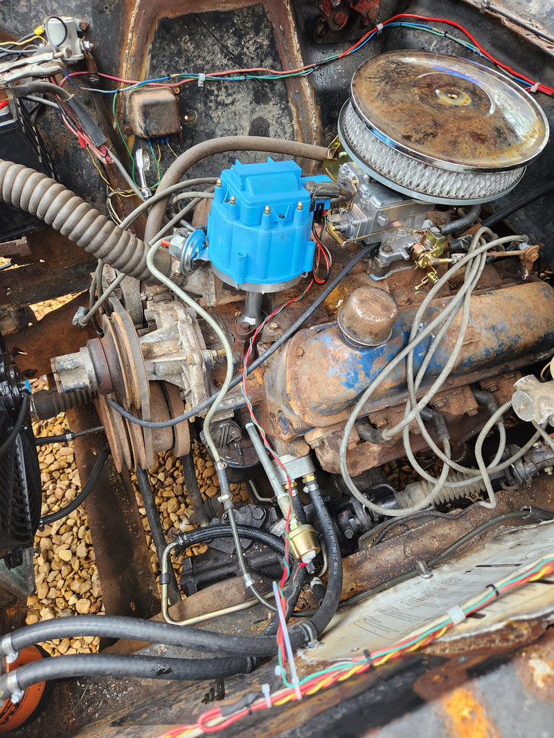
The HEI distributor in place with the pair of wires for power and tach routed, zip tied and plugged up. Note how empty this area of the engine bay is.
On a side note, I did manage to get a pair of universal old style mirrors to install. These mirrors are able to be used on either side due to their design. They're plastic but are covered in a chrome finish to make them look like the old retro style mirrors that would've normally bee on this year range car. All I had to do was line up the mirror base trim and drill a couple holes in the top of the door then secure the mirrors in place on top of the trim pieces. It was a pretty quick and simple installation that further completed another part to this build. 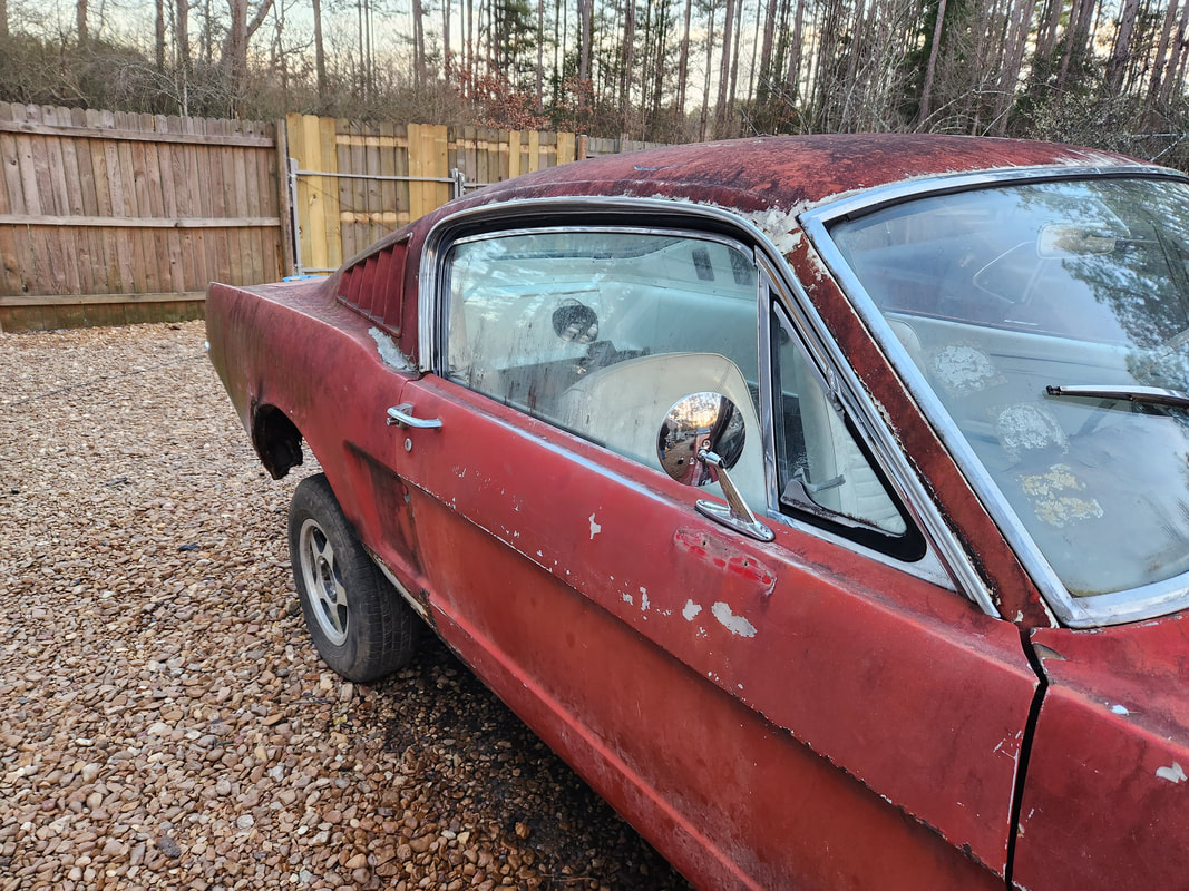
Passenger side mirror installed, note the old spot where a mirror was mounted, just below this mirror's location.
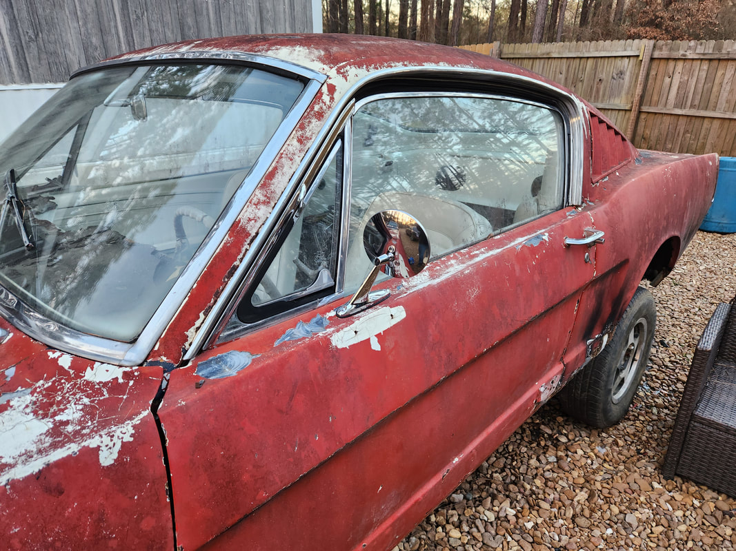
Driver's side mirror in place. Note the old spot where another mirror was installed just below this mirror.
With the mirrors in place, the only other thing really left to install to "complete" the car is the heater box. We're not going to worry about this component at this moment, as we still need to try and get the engine running and go through the tuning up and minor testing of everything. Once I get the engine running, I can then go ahead and get the heater box installed so I can at least say this car will have heating, even though we will probably be close to the point where heat won't even be needed as we are closing in on Spring.
This is an instance of me investing way too much effort to build something that will in the end be completely temporary. I'm not necessarily talking about the mower carb setup in and of itself, but the test fuel system that I'm setting up for the sake of testing for the MPG numbers this system can produce. That fuel system is comprised of a gallon fuel can that will be hooked up to the mechanical fuel pump, as well as a return line set up in place of the regulator, with the tubing being routed back to the gallon fuel can so the majority of the pressure will be pumped around right back into the can, with a light amount of fuel bled off to feed the mower carb. 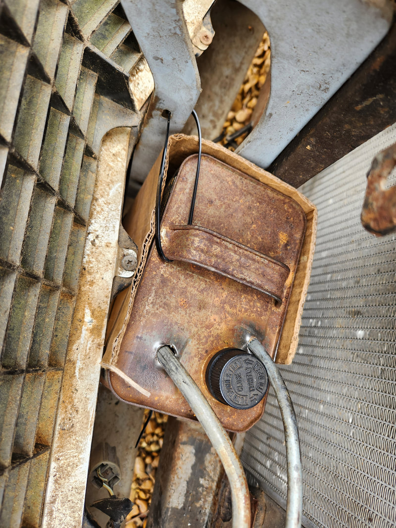 A top view of the fuel can showing how the cardboard is wrapped around the can and the zip ties that are used to secure the can. In this case at the top a zip tie secures the handle of the can to the hood latch support member to keep the top of the can from being able to move around easily. What I really had to focus on was how to secure the gallon fuel can. Since this can is a rectangular can, like an old school gas can, it was able to fit into a spot between the grille and the front of the core support. I had to figure out a way to secure the thing so it won't bounce around when the car is in motion, causing it to spill or even chafe enough to wear a hole in a spot where leaks can occur. What I ended up coming up with was a combination of a cardboard wrap that would cover the fuel can where it's nestled against the metal surfaces where it sits, and the use of zip ties to further secure the can so it won't be able to bounce around in its spot. I had to use a combination of several zip ties to wrap around the fuel can and parts of the support members behind the grille to hold the can stationary where neither the top or bottom would shift or move around. 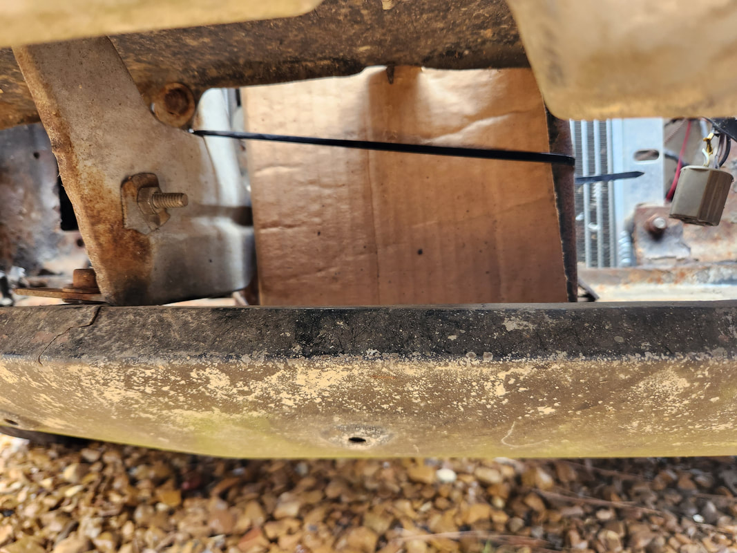 The cardboard piece is wrapped around the gallon fuel can as can be seen from this angle. Note the zip ties as they're wrapped around the can and cardboard to secure it in place. After my bootleg combination of cardboard and zip ties being implemented to create the little nest for the fuel can, I finished up with the fuel input line that would connect to the fuel pump. I had to cut another piece of metal tubing and bend it some, with a small hook that would turn towards the fuel pump nipple. A short piece of rubber hose would connect this short metal tube to the end of the metal tube coming from the fuel can. The rubber hose that was connected to the fuel pump was reused, after disconnecting it from the original fuel line going back to the fuel tank. This hose was bent at a 90 degree angle to connect to the metal tube, completing the input side of the fuel system. The next problem I faced was the idea that the metal tubes were rubbing against a sharp edge on the shock tower. Enough movement would rub a hole in one of the metal tubes, compromising the fuel system. To solve this problem, I cut a piece of heater hose and cut through it lengthwise, then wrapped the hose around the two metal tubes where they make contact with the shock tower. Zip ties secure the hose piece in place, protecting the tubes from damage later.  Heater hose zip tied around metal tubes where the sit against the shock tower. Note the bent rubber hose from the fuel pump connecting to the end of the metal tube. With the whole fuel system done, there's only a couple other things I need to address. One is installing a small nipple in the intake plenum for the mower carb so I can hook up the vacuum advance hose from the distributor. I will have to remove the intake unit so when I drill through it, no shavings end up in the lower intake. I'll have to cut another gasket and prep and glue that new piece back down as well, but it's a small price to pay to keep the engine safe. The next thing is to get a single wire O2 sensor that I can hook up to the single sensor line that goes back to the A/F gauge in the cab. I'll source this from the junkyard, checking for an older vehicle that would've used a simple single wire O2 sensor. Worst case would be buying one online, but even if I did have to get a sensor that had an on board heater, I could still just tap into the sensor wire on the sensor and omit the rest of the wires since we're not using the heater circuit. Either way, as long as the sensor has that nice white frost on the nose, it should be in decent shape. Once those two things are addressed, I should be able to get the system back up and running so I can tune the system and prep it for road tests. There were some small things that I had to do on both the Truckstang and on the lawn mower carb conversion on Rustang. As stated before, when one is so close to the end of a project, the number of small tasks that need to be addressed seems to grow, remining the builder that there are a lot of small details that can be ignored throughout the build. One of those things was the installation of the hood hinges. Because the hood on Truckstang is rusted to hell, being able to use the hood hinges with the locking springs would not be possible. The hood would just fold up under the amount of tension that would be exerted on the front of the hood when trying to break the spring tension. The solution to this was to remove the springs on the hinges. I did have to wet the hinges down with WD40 to loosen them up. When I went to install the hinges, I did have to contend with rusty threads on the bungs that held the hinges. 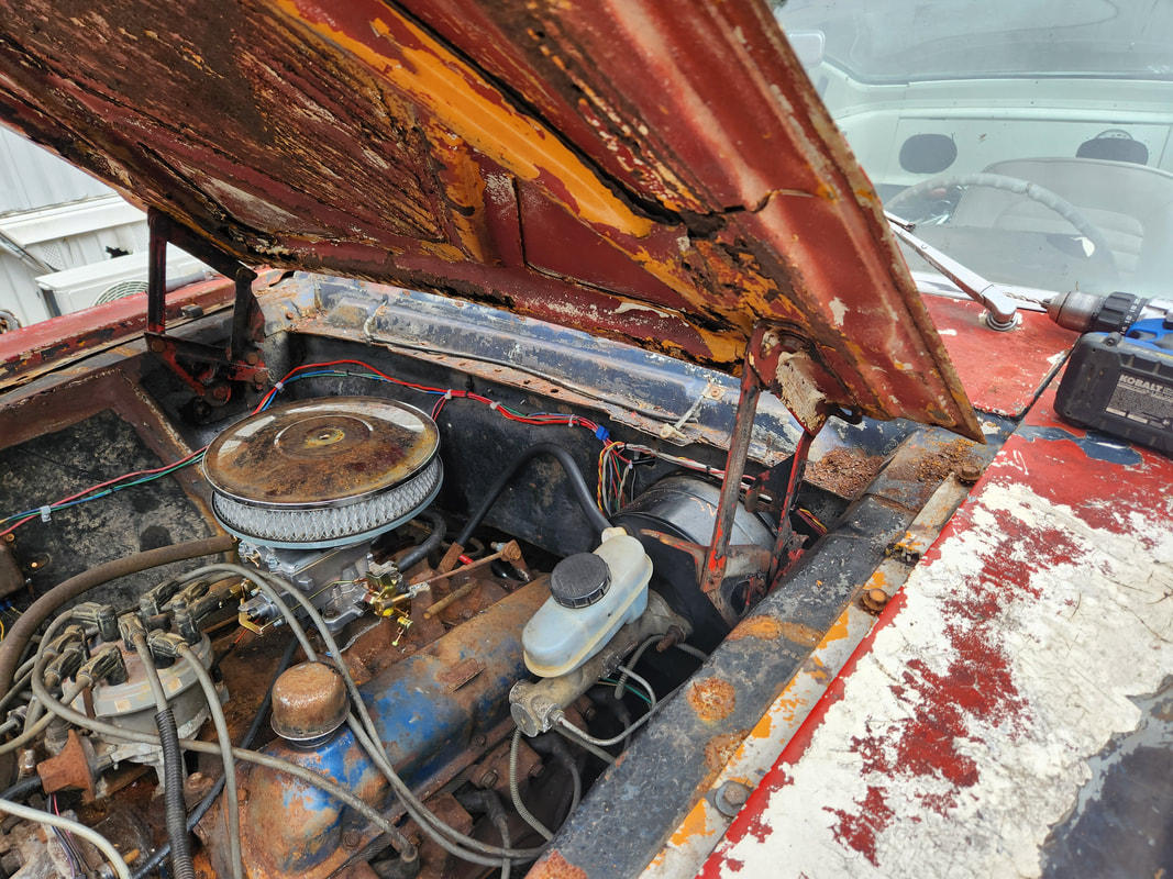 The pair of hinges installed on the car with the hood, sans springs, so the hood can be opened and closed without folding up the hood when fighting against the springs. I will need a prop rod to hold the hood up of course. I ended up having to use vice grip pliers to hold the bungs on the other side of the side panels, under the fenders, in order to allow me to work the bolts through the rusty threads before I could finally get the bolts threaded all the way through. I was able to install all three bolts on the right hinge but the left hinge had a broken bolt in the bung so that was a no go. On the hood side, I was able to install one bolt on the left hinge to secure it to the hood, but the other hole had a broken stud in it. On the other side, I was unable to install either bolt due to one hole having a broken stud and the other hole just being, well, a hole due to the thread bung being rusted away. I solved this problem in a bootleg manner by moving the hinge just a bit to drill a hole just past the bung. I took a lag bolt and force threaded it through the thin metal, securing the hinge to the rusty hood that way. It isn't much but it was enough to hold the hinge in place. 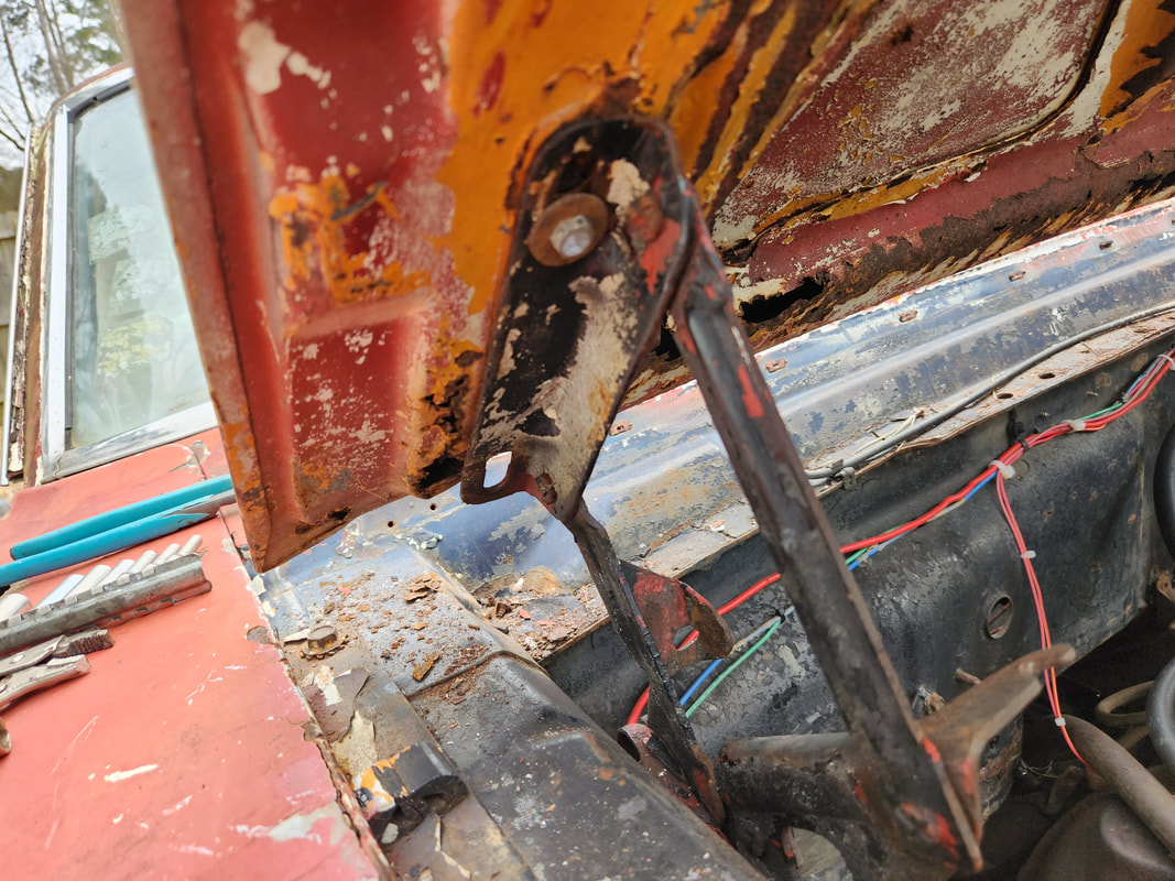 The single lag bolt and washer used to hold the hinge to the bottom of the hood, through a hole drilled next to the damaged thread bung. After a quick adjustment I was able to get the hood situated where it would close as straight as its going to, given the compromised nature of the rusty body panels on this car to begin with. Even with that, the hood was still able to close and latch, with the floppy rusty latch grabbing the catch on the core support. I'll probably have to add something to this to fully hold the hood down because this setup will easily catch some wind and snatch the front of the hood right off the rusty latch portion, leaving it in the core support catch and sending the hood up. I might figure some crude hood pin setup, or even install a legitimate hood pin kit through the rusty hood, only to roll it over to the next hood I do manage to install in the future. 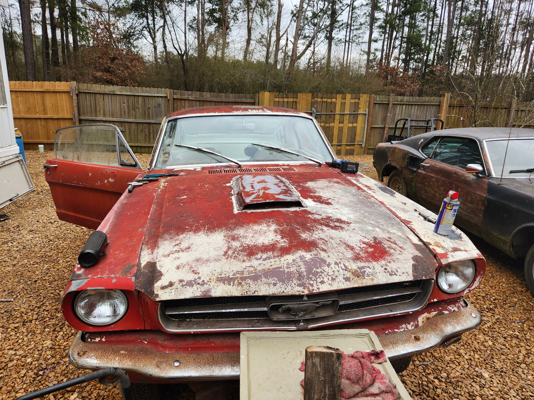 The hood closed and latched down, lined up as best as it's going to be, given the compromised nature of the body panels. With the hood hinged up, all I have to do is source a piece of pipe or something that I can use as a prop rod to hold the hood up in place of the 2x4 I had been using to hold the hood up. With a hood pin kit installed, I may not be in too much a hurry to install a new hood, waiting to source a good specimen for a good price, versus buying a brand new reproduction unit. I am still waiting for my hybrid HEI distributor that I'll be installing in place of the Duraspark system as I don't want to keep running in circles with this old system while trying to get this engine started. Once that comes in, I'll get back to work on this car and hopefully have it running. |
