|
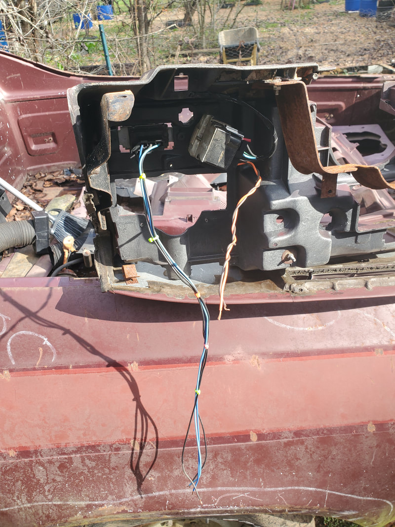
With having the H4 configuration figured out on the headlights and getting the left side light sockets wired in, I moved on to the right side to get those done. Of course they would be a duplicate of the left side, given all the colored wires. Another thing that needed to be addressed but was already figured out was the extra wires in the wire harness that went to the headlights, and parking lights by extension. I figured that the extra wires were for the turn signal light fixtures as well. First things first, getting the right side headlights wired up. 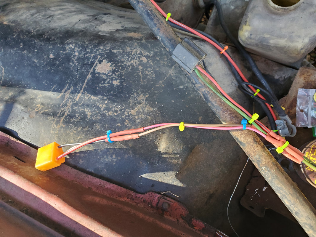 Right side headlight sockets wired up and secured with zip ties. Because of a little mishap on the left side regarding the wire that turned out to be a chassis ground on the old headlight circuit, rather than un-solder the wires and redo them, I just popped the terminals from the plug and swapped them around to be in the places I needed them to be in. I had to do the same thing with the primary light socket on the right side so the colored wires matched up to the left side. After this little detour, I got everything wired up, soldered up, covered in heat shrink tubing and zip tied to make things nice and neat. Enough wire was used to give proper spacing between the light sockets so there is no undue stress on the plugs when they are in place. Even then with the newer H4 LED's, most of them have pigtail plugs that will give more than enough cable to ensure no stress on any plugs. The next thing was the extra wires in the wire harness. I had a light and dark blue wire and a darker brown wire. Already knowing what was up I checked out the wires going to the side marker lights, and sure enough, the left marker had a light blue wire and brown light and the right side marker had a dark blue and brown wire. 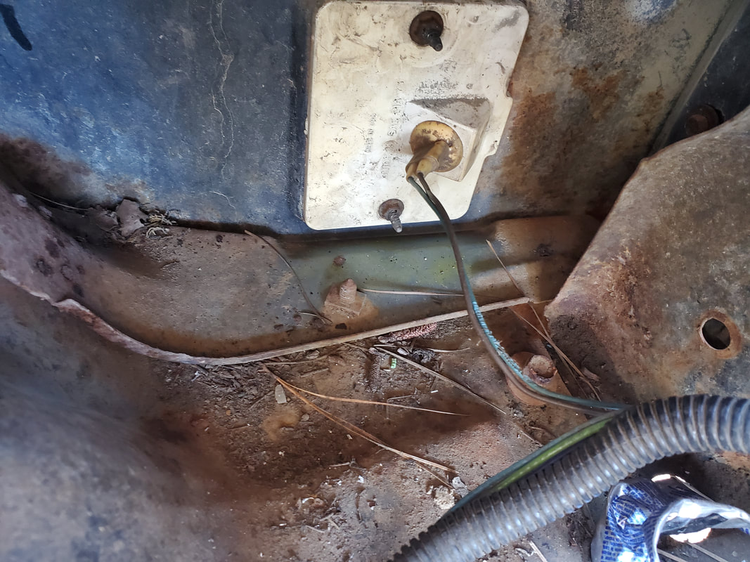 Left side marker light fixture and plug with light blue and brown wires. 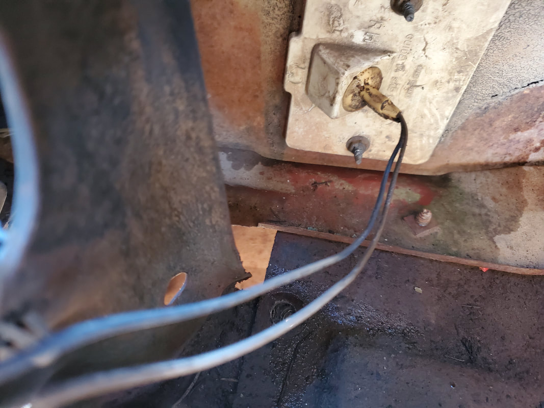 Right side marker light fixture with dark blue and brown wires. At first I hooked up both blue wires to the 12v power feed for the headlights, since the side markers would be a cool feature to have, just for shits and giggles. But then after looking at the turn signal light fixture, I found that it was a two filament bulb that also had a blue wire on it, light blue for the left and dark blue for the right, plus two brown wires, with switched grounds for both filaments. Or maybe the blue wires were the grounds and the brown wires were the power lines. Who knows, either way, that aborted the mission for hooking up the side marker lights to the headlight circuit. Rather than complicate things with this backyard rewiring, I decided to rewire the side markers with the turn signals, which is probably more practical so one can see even from the side when the car is indicating an intent to make a turn, especially since the turn signal light is recessed under the front bumper. With the blue wires cut from the headlight circuit, I added a good length of the same colors of wire to these wire ends in order to give me the extra wire to reach into the cab and up to the steering column. I soldered the extra wire and covered the joints with heat shrink tubing to protect them then tucked the wires in the wire snake going up to the firewall. The two blue wires were fed through the hole in the firewall, along side the wires for the headlight circuit. The brown wire was added to in order to reach the firewall where I have a chassis ground with a couple other ground wires attached. Everything was tucked in the wire snake to keep things neat and of course save on zip ties. 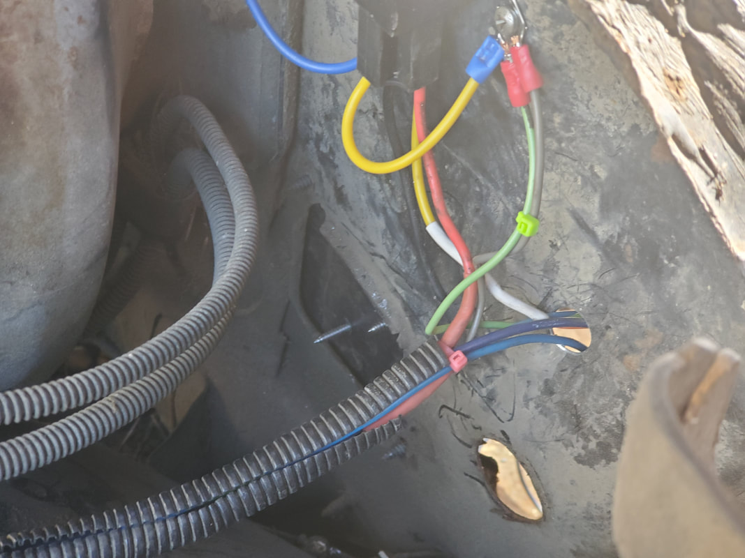 Wire snake with wires running through firewall. Note chassis ground where brown wire, along with other grounds are secured with a screw. 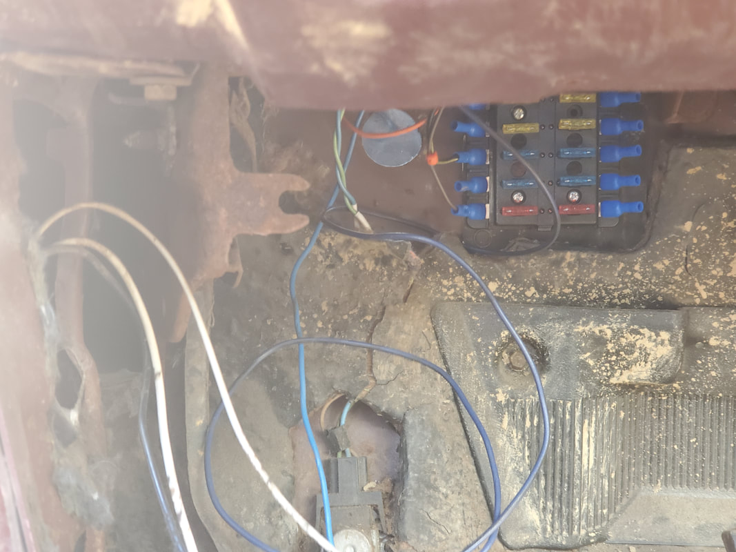 Light blue and dark blue wires from left and right side light circuits routed through firewall to under the dash. As for the turn signals, since the turn signal cam on the steering column is trashed, I will have to do like I did with the 69 Mustang and bolt a metal strap to the side of the steering column holding a SPDT switch that is used as a turn signal switch, in the same way the original switch would've been used, down for left, up for right. I made sure to have enough wire on these two runs to be able to route the circuits up along the routes other wires are taking and up the steering column to where the switch will be mounted. Zip ties will of course keep things neat and orderly. With this taken care of the next target will be the gauge cluster. This component consists of the fuel gauge and clock, both of which will share a 12v power feed, with the clock going to chassis ground and the fuel gauge over to the line feeding the sending unit in the back of the car. There are the two turn signal lights on the gauge cluster that of course will be spliced together with our blue wires from the front and into the switch that I'll mount on the steering column. Lastly, the dash lights to illuminate the gauge cluster will have a power feed routed down to the headlight switch circuit where it hooks into the fuse box. The taillights and these dash lights can be hooked directly to the fuse box since they are of a low enough wattage to be able to be handled on the circuit. The ground for the dash lights will of course go to chassis ground.
0 Comments
With the preliminary tasks taken care of in the wiring of the Elco, I picked a target area to start my rewiring. Since the dash frame was in place, the first target circuits I chose were the wiper circuit and headlight circuit. For all intents, these two circuits are two difficult circuits to map out and get wired since the wiper motor typically has four wires on its plug while the headlight circuit, especially when rewiring for a different configuration, has the added difficulty of trying to figure out what wires on the headlight sockets go to power in, high/low beam, ground, or whatever. There's also the matter of figuring out which wires on the headlight switch go where, same as the wiper switch. The wiper switch may typically have four wires on it as well, especially with those that have the integrated washer motor switch. As for the headlight switch, since I always wire this circuit to turn everything on at once, with the high beam being operated off of the standalone switch typically present, I only need to use the headlight switch as a regular on/off switch.
Starting with the wiper circuit I started ohming out the wires to see which ones get continuity in the different switch positions. It took me a little playing around and going in circles, which was stupid on my part because I could've gotten steered in the right direction from the start if I had just researched for a wiring diagram/schematic. Upon doing this I found that power actually comes in at the wiper motor on its terminals, with a power feed going to the washer pump, which is integrated on the wiper motor assembly. The switch wires all go to the wiper motor, with no wire going to the fuse box. On the switch, according to the diagrams, it had three wires that switched the wiper motor and activated the washer pump. The fourth wire was a ground. Running all four of these wires through the firewall to the wiper motor, I terminated the ground on a terminal secured to a screw in the firewall. With the other three color coded wires hooked up to the three wires on the wiper motor, I ran the power feed wire back through the firewall and hooked it up to one of the terminals on the fuse box. 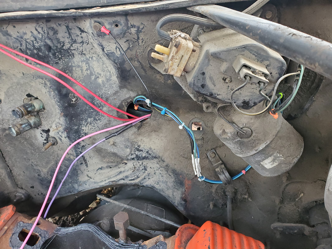
Wiper motor assembly wired up with wires from switch in cab. Everything is secured with zip ties to keep things neat.
With the wiper motor circuit taken care of, the fun part began, the headlights. Even though the H4 configuration headlights share the same plug as the older style headlights on these cars, the pinout is way different. The H4's utilize a switched ground concept where a single power feed goes into the light and the high and low beam selection is done via switching grounds on for either side. Because of this, the plugs have to be completely rewired from their original configuration. Since the plugs on this car were dry rotted, I had to replace them with some fresh pieces, well I had two new plugs and two salvaged plugs that were still in good shape. I ended up having to use the 69 Mustang as a reference for the pinout of the plugs since I rewired that car for H4 LED headlights a good while back. With the new pinout figured out, I went to work wiring up the left side of the headlight circuit. On the wiring harness going to the lights, the ground wires that were secured to the chassis ground were hooked up to the ground for the low beam lights. Contrary to what I said, I figured out a way to do a hybrid wiring setup for this crap. First things first. The headlight switch on the dash, being a simple on/off switch, will be used to switch an automotive relay, as I've done on previous wirings. Power was routed from the fuse box over to the switch and out from the switch to the automotive relay. The other side of the relay coil was routed to a terminal grounded on the firewall. As for the switched contacts, an inline fuse was hooked up to one side of the relay to feed power in from the battery while the other side of the relay will send power out to the power in terminal on the headlight sockets. While this power will feed both high and low beams, only the ground for the low beam is on a constant hookup, making the low beam lights a switched power circuit, not a switched ground circuit. 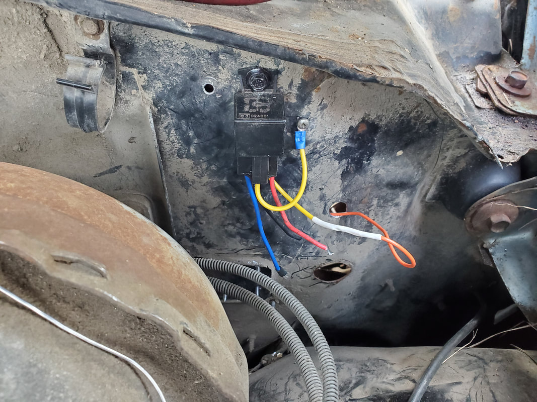
Automotive relay used for switching on the low beam headlights. Unlike previous headlight wirings, I will only be using one relay in the whole circuit.
Now for the high beams. Since this car has a floor switch with three wires, I had to isolate two wires, using the floor switch as a simple on/off switch, just like the dash headlight switch. After getting my two wires and hooking up some extra wire of the same color to reach out through the firewall, I got to work on the outside. I did have to drill an extra hole in the firewall near the fender shield so I didn't have to run too much wire to go to the middle of the firewall then back to the fender shield. With that little bit of business out of the way I started concocting how to do the high beams. This involved taking the other headlight plug and hooking up the 12v feed, which taps off the low beam 12v feed, which is switched via the automotive relay. From here I took both the high and low beam grounds of the two remaining terminals and wired them together, then spliced into the wire from the high beam side on the primary low/high headlight plug to add that high beam circuit to the mix. The high beam only light socket will switch both sides of the light on at the same time in high beam mode while grounding the high beam side of the primary lights as well. 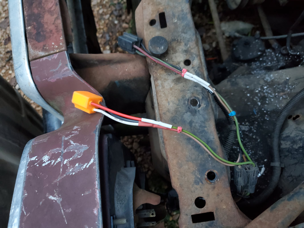
The high and low beam light sockets for the left side all wired up using solder joints and heat shrink tubing along with zip ties to make things nice and neat.
This ground wire for the high beam on the primary light, still in the wire harness, was isolated on the cut off end and spliced into one of the wires going back to the floor switch. The other wire on the floor switch was terminated with a terminal on the firewall. This provided the switched ground for the primary light's high beam and the complete switched ground for the high beam only lights. In essence the high beam light circuit has two switches in the circuit, the one that switches the 12v that feeds everything and the ground that completes the circuit for just the high beams. I ended up spending a greater part of the day getting all of this figured out the way I needed it to be for it to work, so I only managed to get the left side done before it got too dark. Of course the right side of the headlight circuitry will just be a duplicate of the left side, using the color coding of the wires as reference to get the right side wired up just the same. I did take advantage of a wire snake to cover up the bundle of wires going back to the firewall so I can save on zip ties. There were several extra wires that weren't used in the harness however. I know that one or two of these wires are for the side marker lights on the front fenders. I'll wire these up to the 12v line feeding the low beams as these will come on at the same time with the low beam lights. Once everything is figured out, any remaining wires will be cut from the harness to keep things less cluttered. 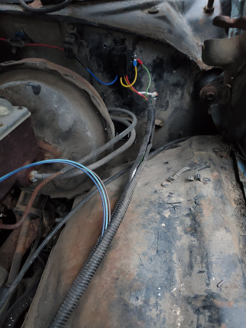
As for the taillights, I will have to hook up the light sockets on the rear bumper to the harness going back into the cab then put power on the wires to see which ones light up the four taillights at the same time. Once I get that line mapped out I can run a line over to the output side of the headlight switch in the cab. Instead of hooking the taillights to the main headlights, the taillights can be hooked to the fuse box, saving on the amount of wire to be run as I won't have to worry about running wire out to the engine bay to hook up to the side of the circuit working off the automotive relay. Of course with the conclusion of the headlight circuit wiring, this allows me to fall right into the gauge cluster/brake lights. Since I'll have the rear lights plugged up, I can then get the brake lights hooked up, along with the turn signals in the dash and outside. I also managed to fish out a single DIN radio shell left over from another vehicle, stored in the trailer, that can be used for getting the radio mount set up in the dash. I also had a triple gauge cluster on the shelf in trailer that I can put to use. This gauge cluster was an online purchase and even though it has a voltmeter versus an ammeter (which I do not want), the oil pressure and temperature gauges are in the metric system. The temp gauge is in Celsius and the oil pressure is in whatever unit of measure for pressure in the metric system. Only solace I can take from these gauges is the idea that the displays are marked by scale so even when I don't know exactly what the measurements are, seeing the needle in the middle to high for the oil pressure would be a good thing and the middle to low for water temperature would also be a good thing. Its nice for me to be able to have a lot of the stuff in house to get the wiring done on the car, including battery cables, flasher relay w/plug, and plenty of wiring salvaged from old wiring. As I progress and eliminate circuits on the car, the wiring job will get that much simpler as there will be less circuits to sort through.
Sticking to the plan regarding the fence, we picked up another fence panel to install on the eastern fence line continuing south towards the eastern gate. As before, we had to move the panel across the compound to the east fence line, which wasn't as simple as just pulling the truck over to the back. Given the fact that there are vehicles blocking every avenue to the eastern fence, we had to muscle the panel over to the spot to get it installed. With all the other equipment set up on site, the installation went faster than before. Only thing different we had to do was cut a small angled piece out of the end to mate up to the last panel, which was at a slight angle due to the grade of the ground. Conveniently, after mating the panels together end to end after cutting out the angled piece of the end, I didn't even have to worry about adding any extra 2x4's to the posts on either end to provide an attachment point for the panel. 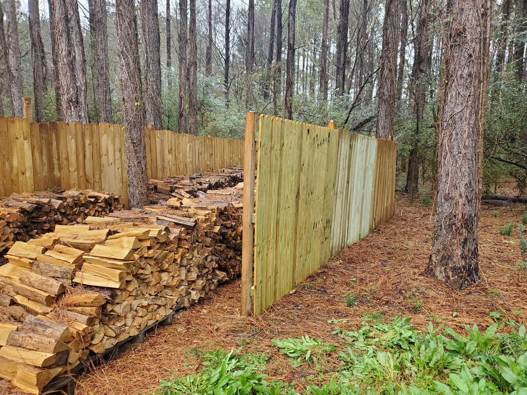 Second panel erected along eastern fence line. With this panel in place that leaves seven panels before we reach the eastern gate. Eventually we'll have the firewood staging area fenced in completely and with that I can move on to laying gravel over the remaining area leading up to the firewood staging area. 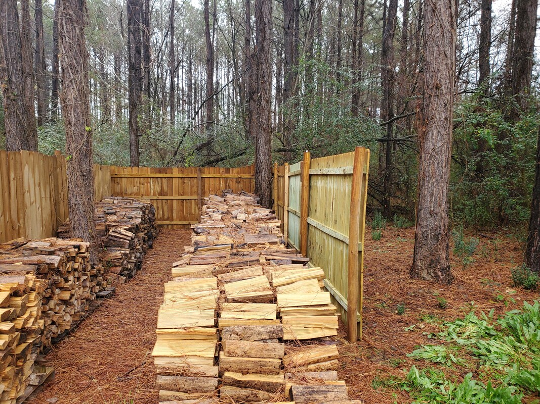 Firewood area with second panel set up, closing everything in. While getting the fence panel we did take the liberty of getting some more flats of lettuce that were still available despite everything being transitioned over to Christmas trees and the like. Weather for all intents has still been relatively mild that the current salad greens we have planted in some of the raised beds are still going strong. Adding more to the raised beds that I pulled the sweet potatoes from will allow us to continue to get use of the raised beds even in this "off season". Even with these flats of lettuce, the selections were pretty few and those flats that were different than the regular leaf lettuce only had three or four individual plants versus the full six plants per flat so it was two flats of leaf lettuce for us. 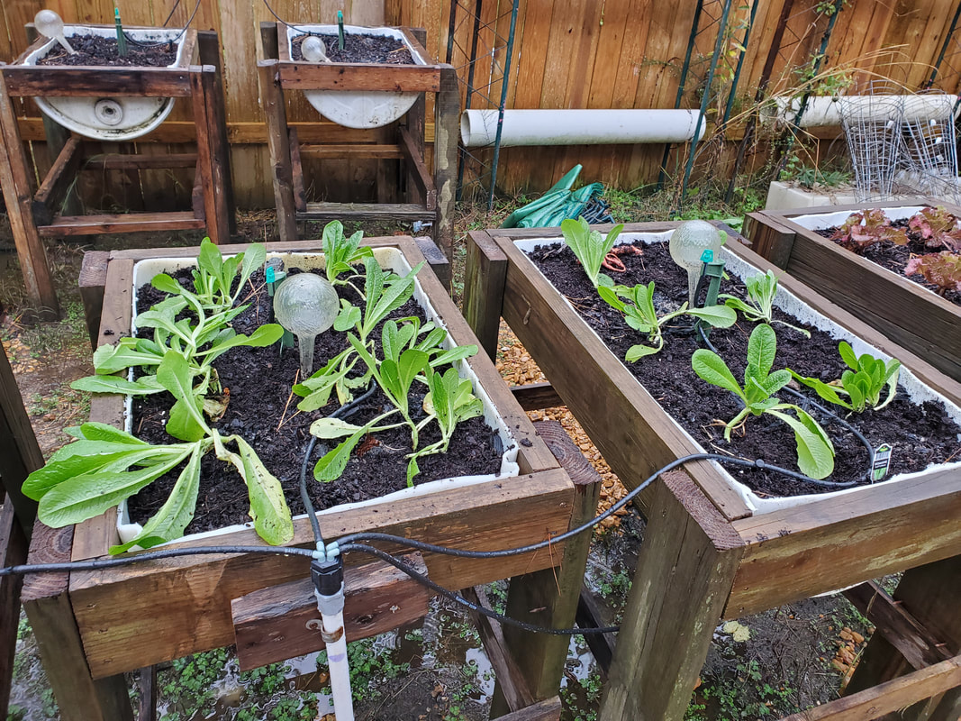 With the moist weather and periodic rains, we didn't even have to run the micro irrigation system at all to keep the raised beds irrigated. More than likely this will continue to be the case. I may actually get some drop cloth and try to set up some kind of makeshift cold frames to cover up the occupied raised beds in case a freak cold snap does show up. It would be cool to be able to throw down some kind of makeshift frame made of PVC pipe then drape plastic over the whole works to cover the things up to keep the greens protected in their own little greenhouses. Such an assembly can be easily dismantled and stowed away where the plastic can still be reused later without it degrading from setting in the sun too long. With the leftover PVC that we have on the rack, I may very well be able to whip up some frames to place over the drum raised beds that won't cost much outside of a few extra PVC fittings. I more than likely still have some plastic laying around as well. On a lighter note, while in the garden I did overlook one raised bed that had a potato plant that had already died back but was forgotten about long before I harvested the sweet potatoes. For the hell of it I stuck my hand in the dirt and rooted around, and was pleasantly surprised to find a single large spud along with a few smaller ones, still well preserved in the cool soil. I dug these all up and washed them off, waiting for the opportunity to cook them up in some dish, knowing that our own work produced what we're eating.  Small batch of spuds harvested from the raised bed with the single potato plant I had left. We had long since harvested the other potatoes, many months before. We had other potato plants in the other raised beds but the main batch was harvested sometime this past fall. The single potato plant spawning these spuds was the last holdout, waiting until late fall to finally die back. But back to the cold frame idea. With such a setup I could actually get some early starts to seed potatoes as well as other plants in the pre-spring weeks. I can even plant commercial flats of plants earlier than usual and cover them up while they grow, allowing them to get a well established foothold in the raised beds so by the time the weather does break, those plants will already be ahead of the game.
We've finally made it to the point where I start the rewiring job on the Elco. After gutting the old wiring and pulling the dash frame out in order to rework the HVAC system, I managed to get my aftermarket fuse box and fish out some other components I happened to have in storage so I can get a good start on the project. The first thing was to obviously get the fuse box mounted. This involved cutting a piece of sheet metal and screwing it in place over the opening where the old junction block used to sit. Covering this large opening also provided a good mounting surface for the fuse box.
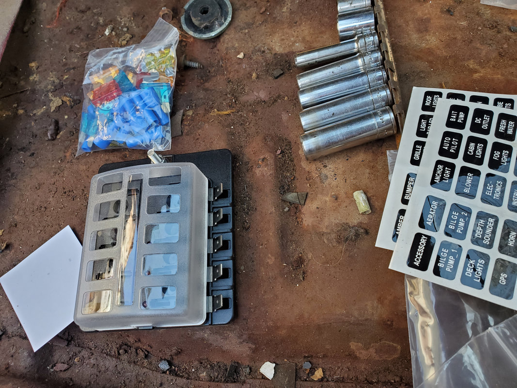
The fuse box with its pack of fuses and terminals and even labels for the fuse box cover to identify the circuits.
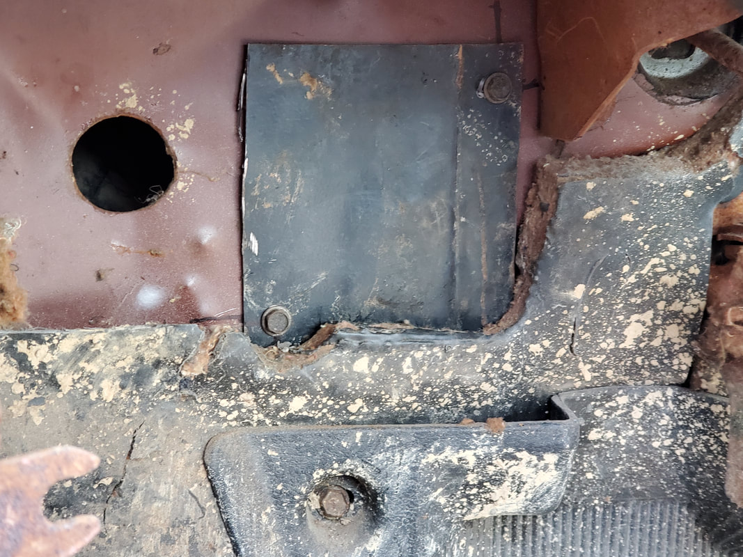
Sheet metal patch screwed in place over the old junction block opening to provide a mounting surface for our fuse box.
Unlike the same fuse box that I bought that was put in the Dodge, this one conveniently came with female crimp terminals to mate with the male terminals on the fuse box, along with mounting screws and fuses. Even though the fuse box has ten slots, more than likely I won't use any more than maybe six slots, since there really isn't a lot of stuff to run on this car. 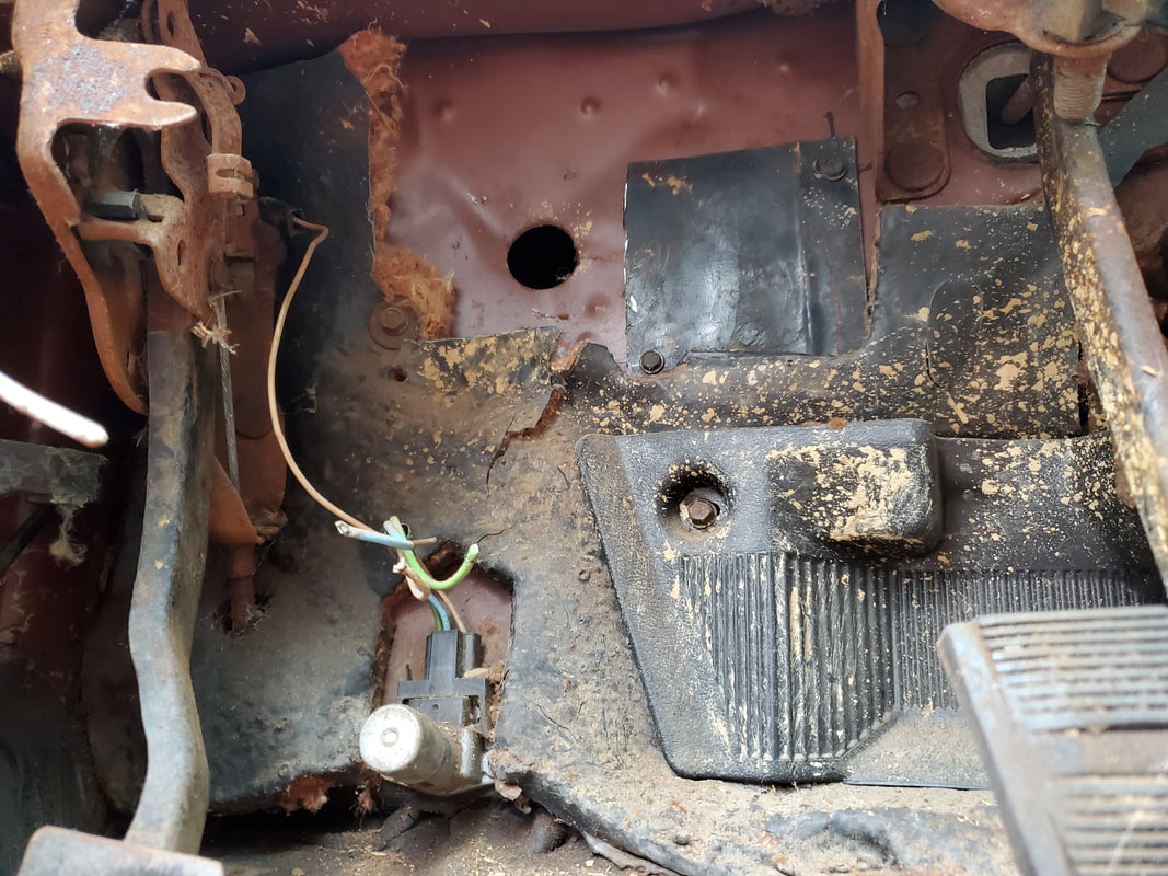
Zoomed out shot of metal patch. Also note the floor dimmer switch that will need to be wired in to the new circuitry.
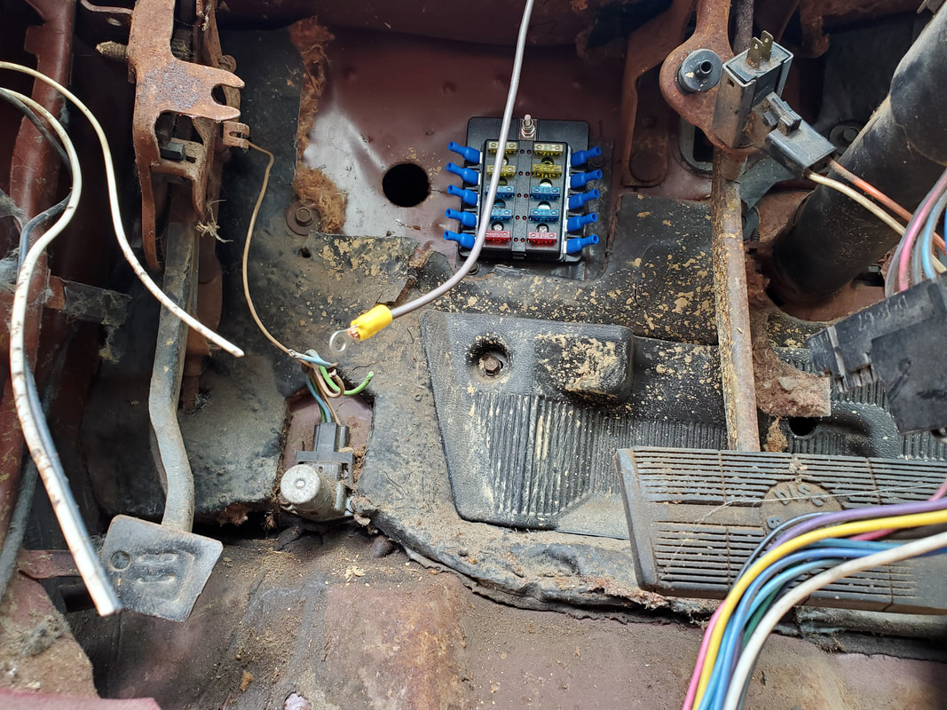
New fuse box mounted on sheet metal patch with female crimp terminals in place on fuse box's terminals to have them ready.
The next order of business was to start isolating circuits on the different plugs that would be wired up. The gauge cluster has a multi wire plug for the dash lights, turn signals, idiot lights and fuel gauge. The clock on the gauge cluster has its own plug as well as the plugs for the wiper switch, headlight switch and HVAC blower motor and AC clutch switch. On the steering column there's the ignition switch block which I needed to identify the wires so I can isolate which wires will be the +12v power feed into the switch as well as the output to the fuse box, switched on via the ignition switch/accessory switch. The wire for the starter also needed to be isolated and the wire that stays hot in both accessory and start modes needed identification since the engine needs power all the way across both positions. The wire loom going to the rear of the car for the brake/taillights was already isolated. As for the turn signal lever, that device along with the rest of the top of the steering column is trashed so more than likely I'll just install a SPDT switch like I did with the 69 Mustang to serve as a makeshift turn signal switch. As of right now the ignition switch is only able to be activated with a screwdriver levering against the rod that pulls the switch into the on/start position, since the column and key cylinder are damaged/missing. 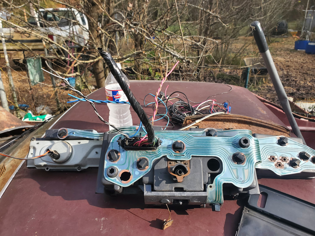
Gauge cluster backside showing printed circuit board which aided in tracing the specific circuits for the fuel gauge, dash lights, and turn signals, the only devices that will be getting hooked back up. An aftermarket gauge cluster for battery power, oil pressure and water temperature will be used in place of the idiot lights so there's no need to wire those back up.
Backside of the dash frame showing the switches for the wiper and headlights with the wires isolated for the headlight. Since the parking/taillights/headlights/dash lights will all be wired to come on simultaneously, I only need two wires on the headlight switch, basically using the assembly as a simple on/off switch.
Since all the headlight associated lights are going to be on at the same time I just pulled two wires to wire in so I can use the headlight switch as a regular on/off switch. The floor switch will operate the high/low beams. The plug on the wiper motor is color coded to the same wires on the switch with the exception of a black wire on the switch plug and a yellow on black wire on the wiper motor plug. I'll more than likely put power on the circuit just to test the wiring layout to get the proper placement of wires with the switch plug. The washer motor switch is integrated so that will also be resurrected. The latest thing that I had to do before I really get started on the wiring is reinstalling the dash frame. Since some of the loads' plugs are on the gauge cluster/dash, I need those items in place so I can get a proper measurement of wiring in order to not have excess wire piled up behind the dash, keeping things nice and neat. In the process of installing the dash I put the defroster vent and the chest vent ducts back in place, further completing the HVAC retrofit. 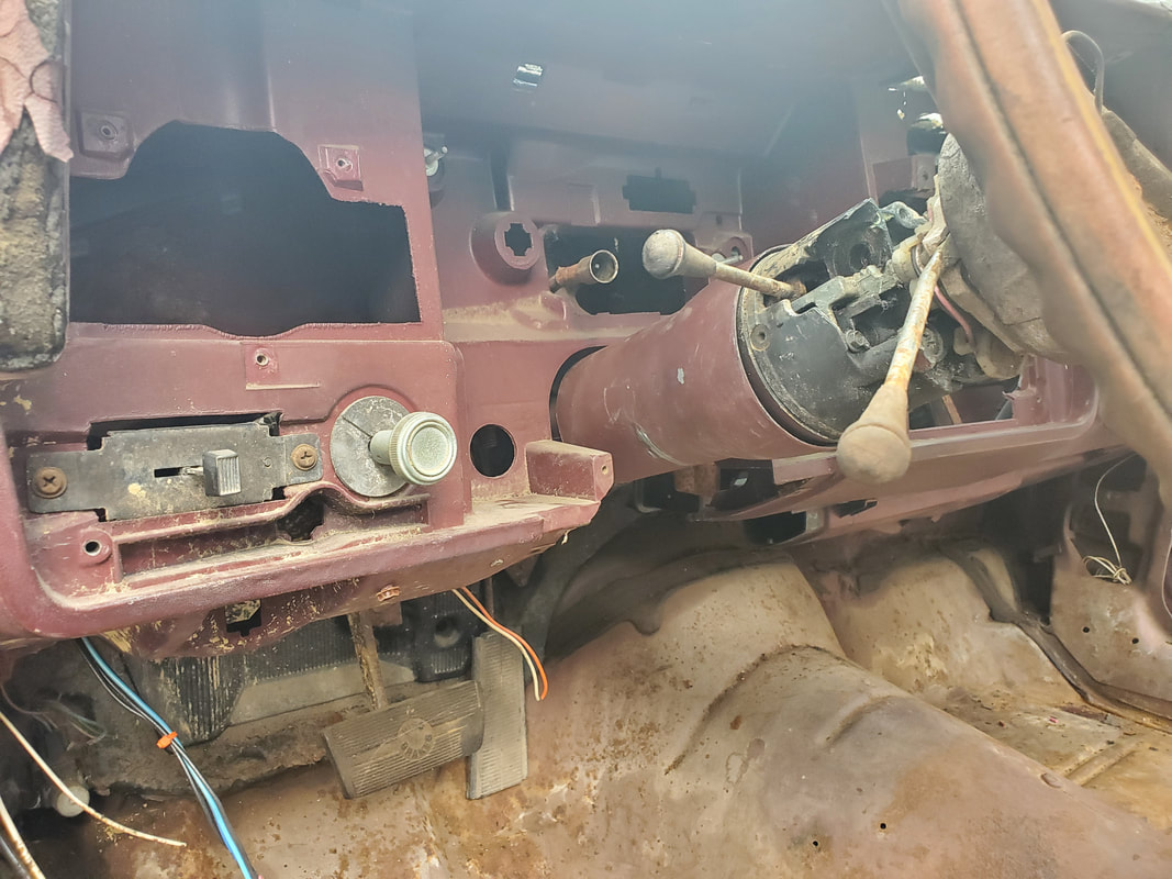
Dash frame hung back in place, using four screws along the top and two lag bolts on the bottom corners.
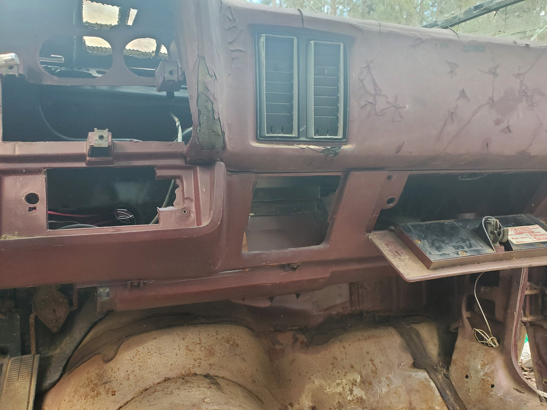
Defroster and chest vent ductwork is remotely visible behind the dash frame from this angle. I will have to cap the ends of the ducts where the tubes would've fed the two side vents, due to the flexible tubes being rotted out.
We have all the power feed wires isolated and wired up, with a positive battery terminal hooked up, feeding power to the ignition switch for both the accessory line and engine power line. The accessory power feed is routed to the fuse box and hooked up along with the power line for the starter solenoid. All these wires are routed out through the firewall to the engine bay and staged about where they will need to be when the actual loads are installed. I will need to splice in an inline fuse for the engine power circuit but that won't be that big of a deal. In fact I have a little plan to put the inline fuse in the engine bay where as a security measure I can pull the fuse, rendering the car unable to be started. We'll figure it out as we go along. This is up my alley, shooting from the hip. We'll get it done though.
After having been on vacation for a while and tackling some other projects we finally managed to get back into the routine of getting gravel to spread out on the grounds within the compound. As of the last gravel episode, we were still trying to cover the garden up. We finally made it to the back of the garden where I recently pulled up some old remains of a raised bed as well as chopped up the remnants of a tree. There isn't much space left to cover in the garden before all main walkways are covered. I will still continue to spread gravel within the garden underneath the raised beds, which will require shoveling the gravel from the wheelbarrow under the raised beds. No biggie, it won't take long to cover those areas before I can fully write off the garden. 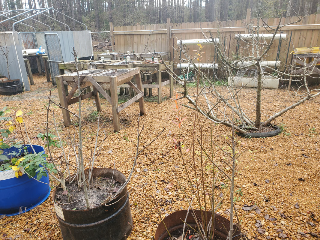 Back area of the garden covered with gravel. Note the newer raised bed row that was built not too long ago that is just about surrounded by gravel. Its good that we managed to get the garden grounds covered up now because as we continue to build raised beds and other garden apparatus, those units can be placed right on top of the fresh gravel, versus on dirt where I would've had to spread gravel underneath later on, as is the case with the current raised beds. The garden has definitely come a long way from the days of its infancy. 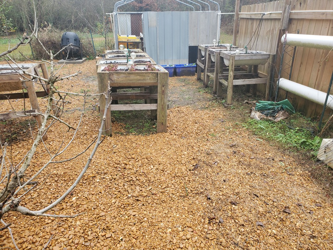 As the last pic shows, there is only a small area of walkway left to cover before all that's left are the undersides of the raised beds. Another smaller area remains along the fence line where I was also in the process of building some permanent hydroponic garden fixtures. With the gravel session done, we also picked up on another project that we've slacked on, which was building the perimeter fence. From the last time we bought fence panels, which has been damn near a year, prices have gone up ridiculously. Last time the whole 6x8 panels were $40, now, they're $53, insane! Either way, the shit needs to be bought so we can get that project done. It's probably better that we just keep getting the panels and hurry up and complete the fence before we get back to where we were back in 2020 when the panels weren't available at any price. 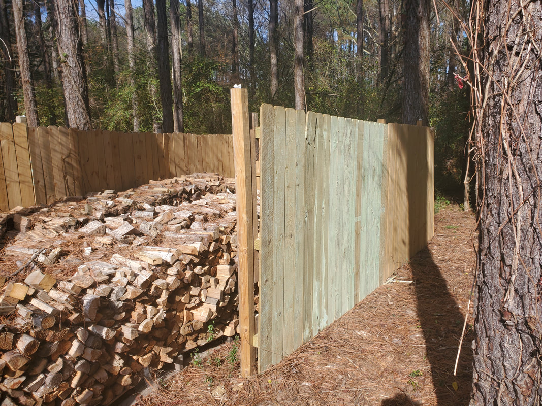 Our single fence panel installed along the eastern fence line, continuing from the northeast corner of the perimeter fence, by the firewood pile. We decided to try and get a single panel per week so we can slowly but surely keep getting the fence done. We're continuing from the northeast corner of the perimeter fence by the firewood pile and working our way south to the eastern gate. After securing this current fence panel it will take eight more fence panels before we make it to the eastern gate. From there it will probably take about that many more to cover the eastern side of the garden and reach where I want to put another gate in the back, closer to the southeast corner of the fence. 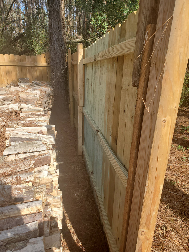 Inside of eastern fence along the row of firewood staged in the firewood staging area. Obviously, its going to take a lot more fence panels before the entire perimeter fence is done. I would hope to be able to get more than one panel on some weeks at some point in order to expedite the completion of the fence but for now we're going to stick with one panel a week. I also still have to complete the northern and western sides of the garden fence just as well as a short run of the south wall of the perimeter fence before I can say I'm done, minus the gates. Now one thing I haven't really checked is if it will be cheaper at this point to get the separate boards to make my own panels. More than likely it's probably neck and neck between the pre-fab panels and the separate pieces so we'll be sticking with the pre-fabs. In the meantime we will get back to other duties around the compound.
Yes folks this is another article on the routine maintenance that has to be done on the car we love and hate at the same time, the Scion Tc. While this car has been rather reliable compared to just about everything else on the lot including the Tracker, when it does come time to do some major repairs, some of those repairs end up being a pain in the balls. In this case that pain in the balls repair is the replacement of the CV axle.
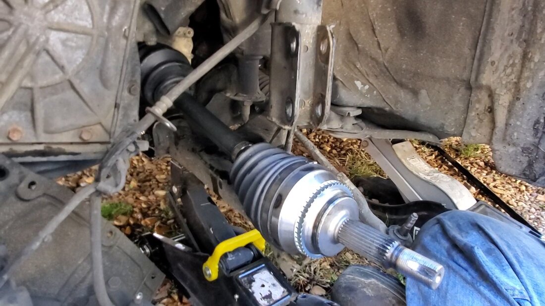
If you remember a while back when we replaced the passenger side CV axle, we ended up doing some Mickey Mouse shit when we left the inner portion of the axle in the transmission and basically disassembled the new axle to allow us to install the new axle into the older inner portion, then replaced the inner boot over the thing to complete the fix. That more or less worked, but now it was time to replace the driver's side CV. I even took time to buy a puller tool, which is a U shaped claw with a threaded point to screw a slide hammer into to allow you to claw around the inner hub of the axle then slide the hammer out to more or less linear pound the axle out from the transmission. 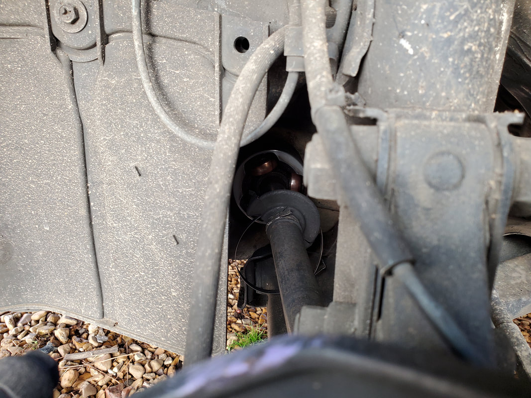
Shot of old CV axle showing missing boot over inner hub and knuckle, exposing the innards of the axle, where the excessive wear took place.
Its funny but everything leading up to the point where I had to pull the inner hub of the CV axle out was smooth sailing. After the tire came off, the ball joint came off with two nuts and one bolt. The tie rod end nut came off and the tie rod knocked out fast. The two big ass bolts for the strut came off fast. Even the clamps for the brake and wheel sensor lines came off fast, allowing me to get the spindle loose. With the battery impact wrench the CV nut came off fast too. As you can see in the pic, the main problem was the inner boot pretty much disintegrated, allowing all grease to get slung out from the innards of the axle, allowing excessive wear. As you can figure, we ended up separating the CV axle, leaving the inner hub in place in the transmission yet again....just in case. I wanted to leave my options open if I have to do a repeat of the passenger side axle. 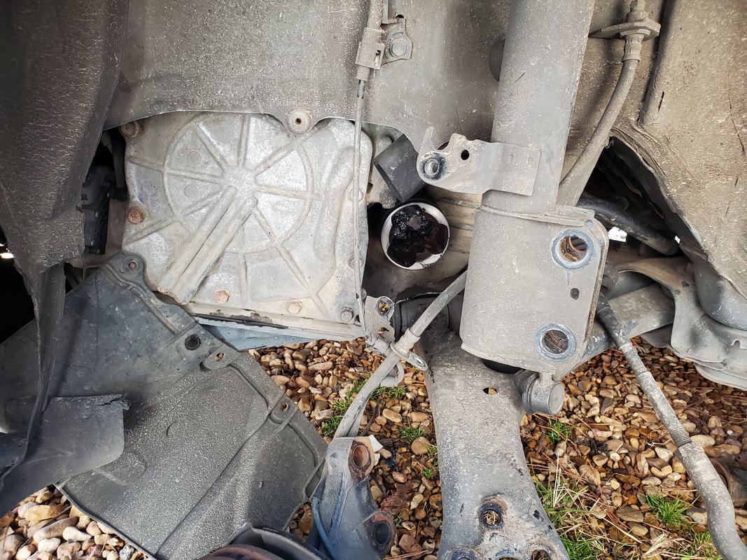
Inner hub left in the transmission after pulling the outer 2/3 of the old CV axle from the transmission.
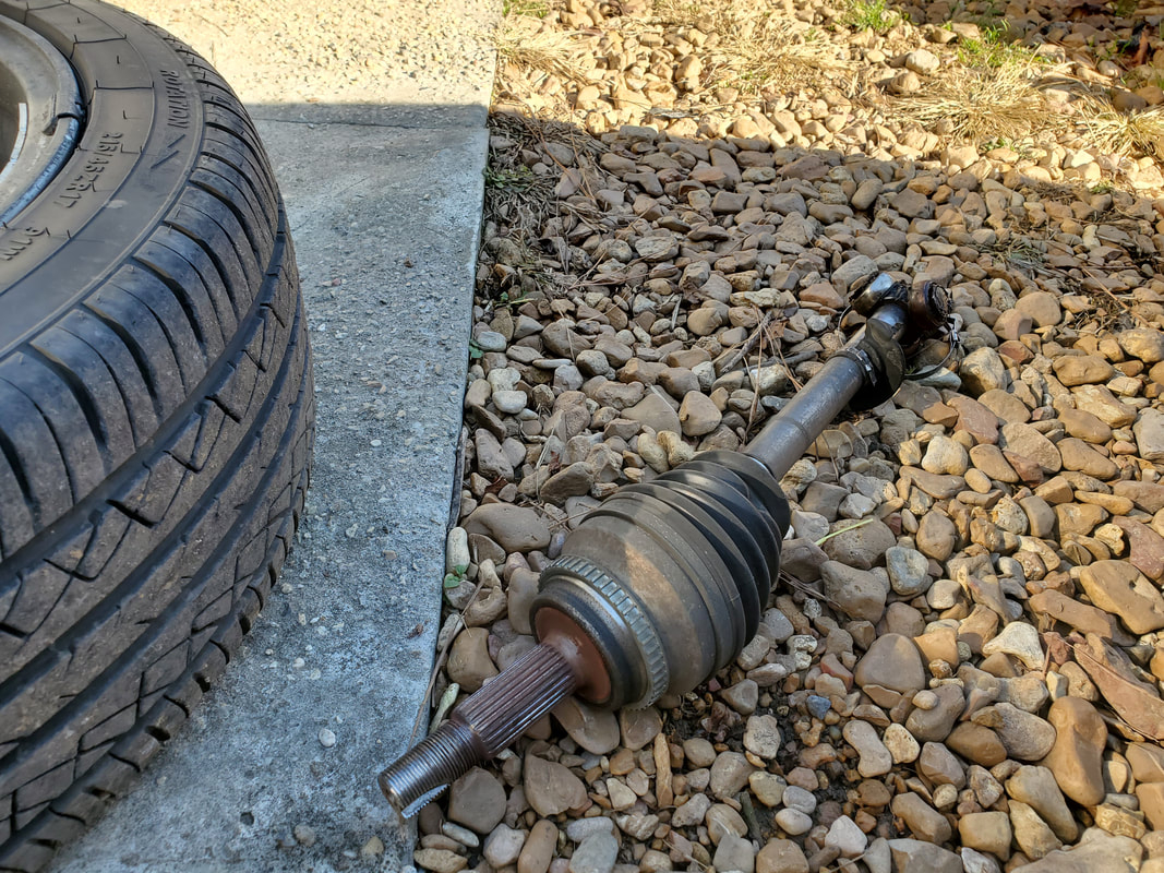
Outer 2/3 of the axle laying on the ground, this is trash. Even the bearing surfaces were discolored to show how the metal on metal action wore the hell out of the components.
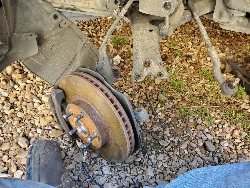
Spindle assembly on ground after pulling everything apart.
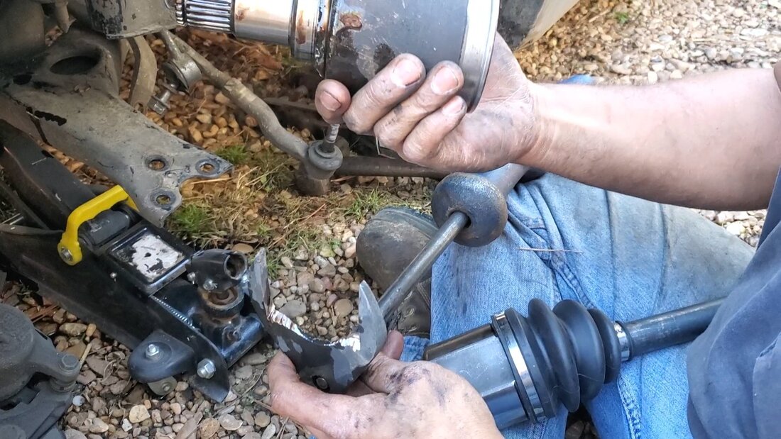
Problem number one came when I tried to put the axle remover tool in place on the inner hub. At first I wondered if the thing had to be tapped in place to seat it, which wasn't happening due to the complete lack of clearance around the hub and the transmission. Then just for shits and giggles, I took the new CV axle and measured the tool against the inner hub on the new axle, only to find out the inner hub was much wider than the tool. What to do? By this time I was already pissed off and rather than do something that might be gravely expensive, I did the least expensive thing, which was take the die grinder to the remover tool. I cut out enough metal from both sides of the U to widen the spacing to allow me to slide the tool between the inner hub and the surface of the transmission. I attached the slide hammer and after some rather rigorous slide action beating the shit out of the tool and the transmission, I finally got the inner hub to pop out. 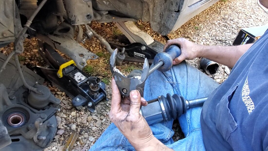
CV axle removal tool after cutting wider with die grinder. Note slide hammer attached to tool.
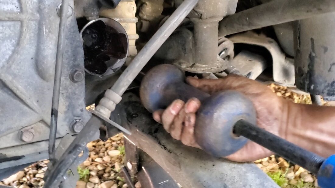
Slide hammering the hell out of the removal tool and the inner hub by association.
Inner hub is out and in hand, along with our trusty modified tool.
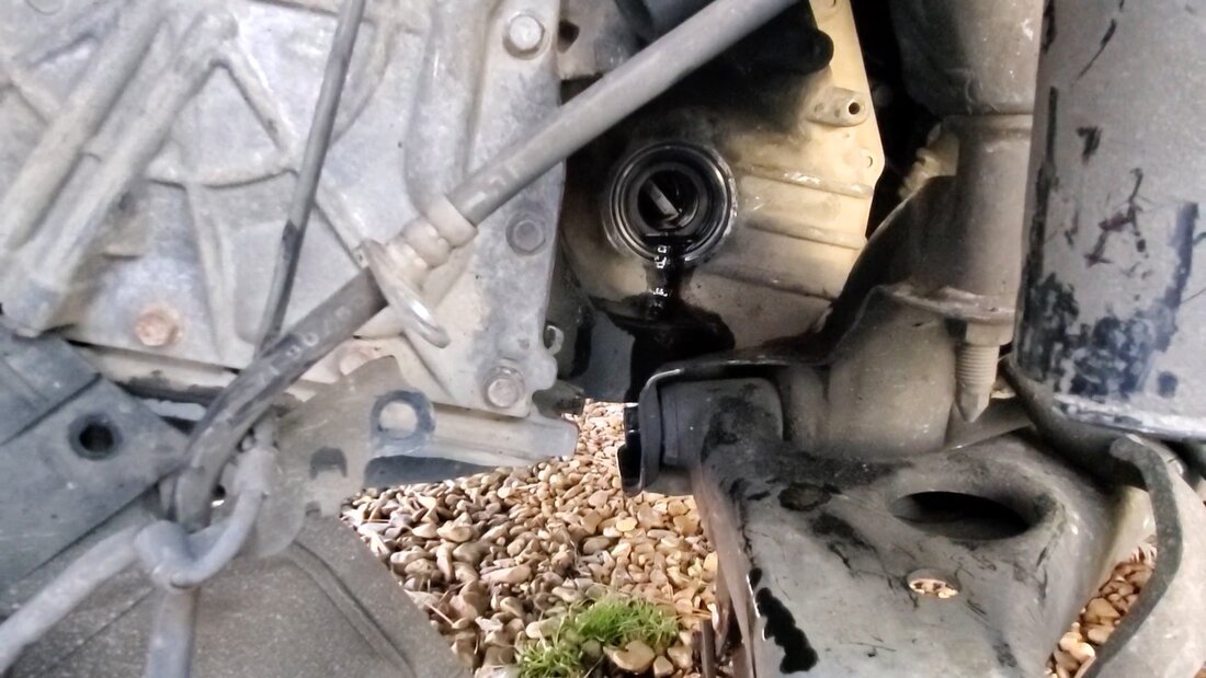
Pulling the inner hub out opened the transmission up, allowing a little leakage of oil.
New CV axle installed in transmission.
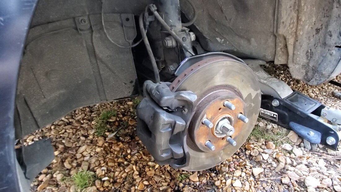
Spindle and everything associated with this central point are all assembled and the tire is ready to go back on.
With the old inner hub out, I was able to slide the new axle in place but still had to lightly tap the end of the threaded shaft with the hammer to get the snap ring to give way to allow the axle to pop into the transmission. I left the axle nut on so I could use the impact wrench to walk the nut off over the damaged end of the threads in order to clean them up. No harm, no foul. With the axle technically in, I was able to reassemble everything in reverse, just as fast as I disassembled everything. With everything together, fresh oil in the transmission, I put the tire back on and took the car for a test drive to verify all was well, which it was. One more PITA job done on this car, hopefully for a good while.
Even though I have the fuse box for my rewiring project, once I got the HVAC boxes installed and everything buttoned back up, I decided to go off on a slight tangent and break down the dash frame. It was mainly for the idea of prepping the dash for the rewiring job soon to come. The dash has a single speaker that even though it looks in good shape, it is old, and rather than reassemble the dash only to have the speaker crap out and me having to pull the whole dash, I'll just replace the speaker now. The makers didn't put a provision for easily replacing the dash speaker so now's my chance to do so. Also I cut away the brittle padding around the speaker opening to A: open up the speaker for better transmission of sound and B: add an aftermarket covering for the dash.
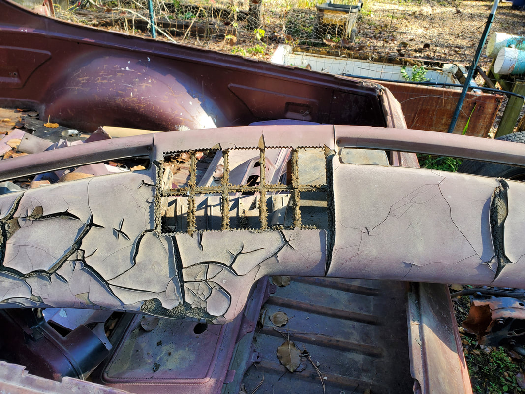
Speaker opening with padding pulled away to expose the opening for a future speaker covering.
Since the speaker installed in place is a regular speaker, to get the type of sound I will need to get with the modern radio that will be installed, I will need to install a 3 way speaker, since I don't plan on installing standalone tweeters. Now I can install 3 way speakers on the sides behind the seats where two more speakers are situated and leave this speaker to be a regular unit that won't require me cutting out any more material from the dash. That may be my main option as most of the sound will come from the rear mounted speakers anyway. Plus this single speaker will be that third wheel that will have to be mounted on the left line or right line of the new radio.
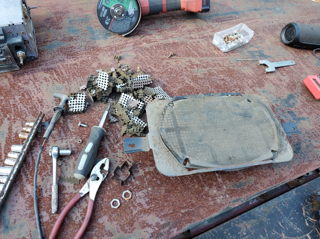
Old speaker along with the fragments of the padding removed from the dash. I will have to install a 3 way speaker and in order to do this I will probably have to cut the metal away from the opening to allow for clearance.
One unique thing I did note was when I removed the stereo from the dash that this thing was an 8 track stereo. For all intents this car had all the options to make it more luxury than utility, with a clock, cassette stereo, cruise control. Only thing it didn't have was power windows and locks. But after removing this stereo, I found that these old units are heavy as hell. I will have to cut out the opening in the dash to be able to install a single DIN radio mount in order for me to install a media player. 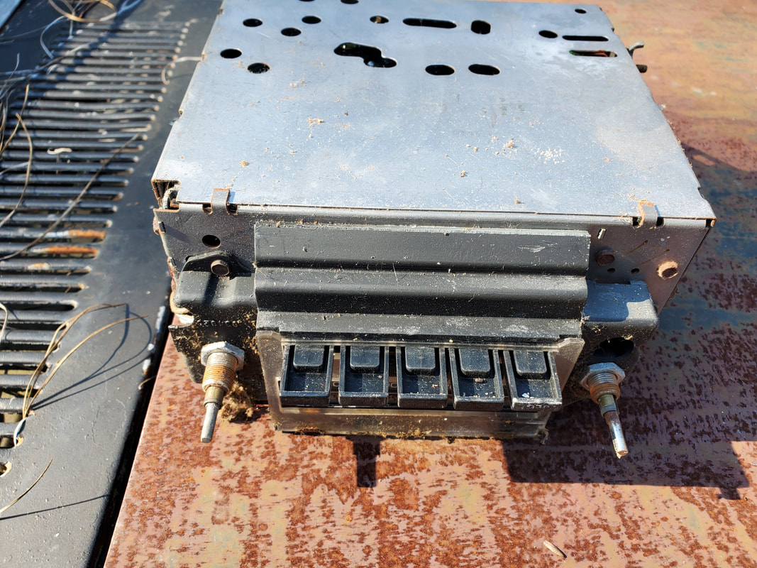
In most aftermarket stereo installs no one uses CD's or other "older" media. Music is played from our phones or from apps through our phones, with the media player stereo using bluetooth connection to connect to the phone wirelessly. Now, "old school" media would be using a flash drive or micro SD card with music to play on a media player stereo. With few exceptions, many people don't even use the AM/FM radio feature of their car's stereo anymore, with even that option being available through our phones. Before we know it there won't be a need for a stereo at all but a bluetooth surround sound speaker assembly, similar to that of a home surround sound system. Only "old heads" will want a regular AM/FM stereo in their cars at that point....
After pulling the inner HVAC box and pulling apart everything to find out what's what, it was time to start making the modifications. Really the modifications aren't mods, but more simplifications of the overall system. Looking at the blend doors I found the one door that opens air to the chest level vents is a two piece door that will further regulate air flow between the chest level vent and the passage that would've moved air to the floor vents. Only thing is, I don't want to regulate air between these two vents, I want to regulate it, or more accurately, blend it, between the defrost and the chest level vents. 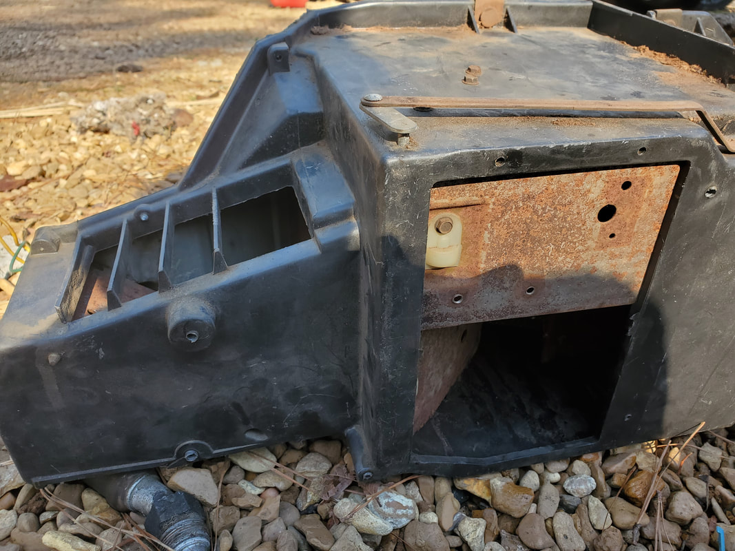 Inner HVAC box with chest level bend door in position where I need it to be in order to regulate the air flow between the chest and defrost vents. 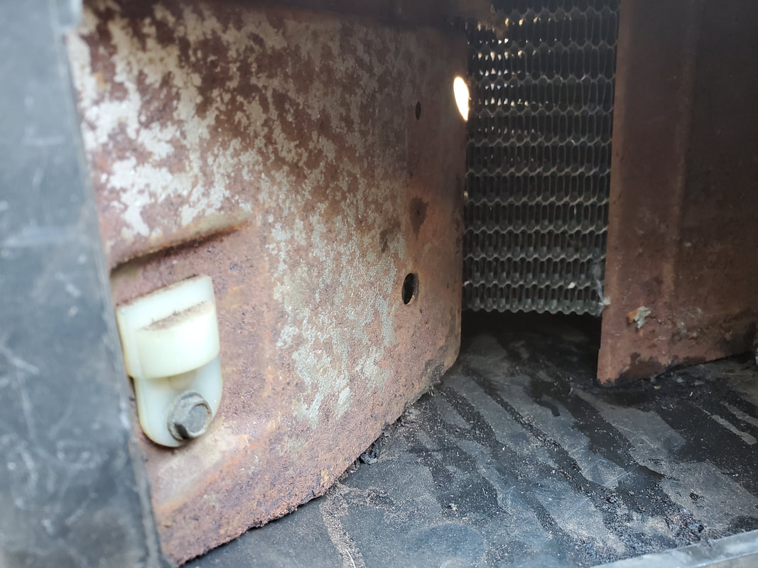 Closeup of the lower blend door half that would help in regulating the movement of air between the chest vent and defrost vent. To do this I closed the top half of the chest level blend door and opened the lower portion. Closing the top portion of the vent will allow air pressure to build up within the small area just past the heater core and only let a small amount move through the open bottom vent. The lower portion closes against the heater core, only leaving an opening above it for a regulated amount of air to pass over that opening and into the channel that would feed the floor vent and defrost. To hold the top portion of the vent in the closed position, I drilled a small hole in an extension of plastic on the outside of the box in order to place a screw that would hold the linkage for the top half of the blend door closed. Doing this will allow the new placement of the blend doors to do what I intended them to do while not rendering the HVAC box unable to be reverted back to the original state, if I, or a successor of ownership, so desires. 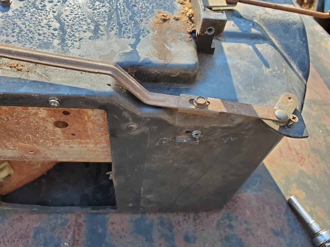 Lower blend door linkage pinned in the open position with a single screw on a flap of plastic, as seen to the right in the picture. Also note the screw holding the top half blend door in the closed position via a hole drilled through the blend door edge to use an existing hole in the box to place the screw through. Now its time to go off on a tangent. The only original blend door control that we will be keeping is the door that regulates air movement between the AC and heat. Unlike the other blend doors, this is the only one that uses a cable to control the door's movement. The cable is connected to a lever on the control panel that allows for fine tuning of the position of the blend door to regulate the amount of hot and cold mixing in the HVAC box. 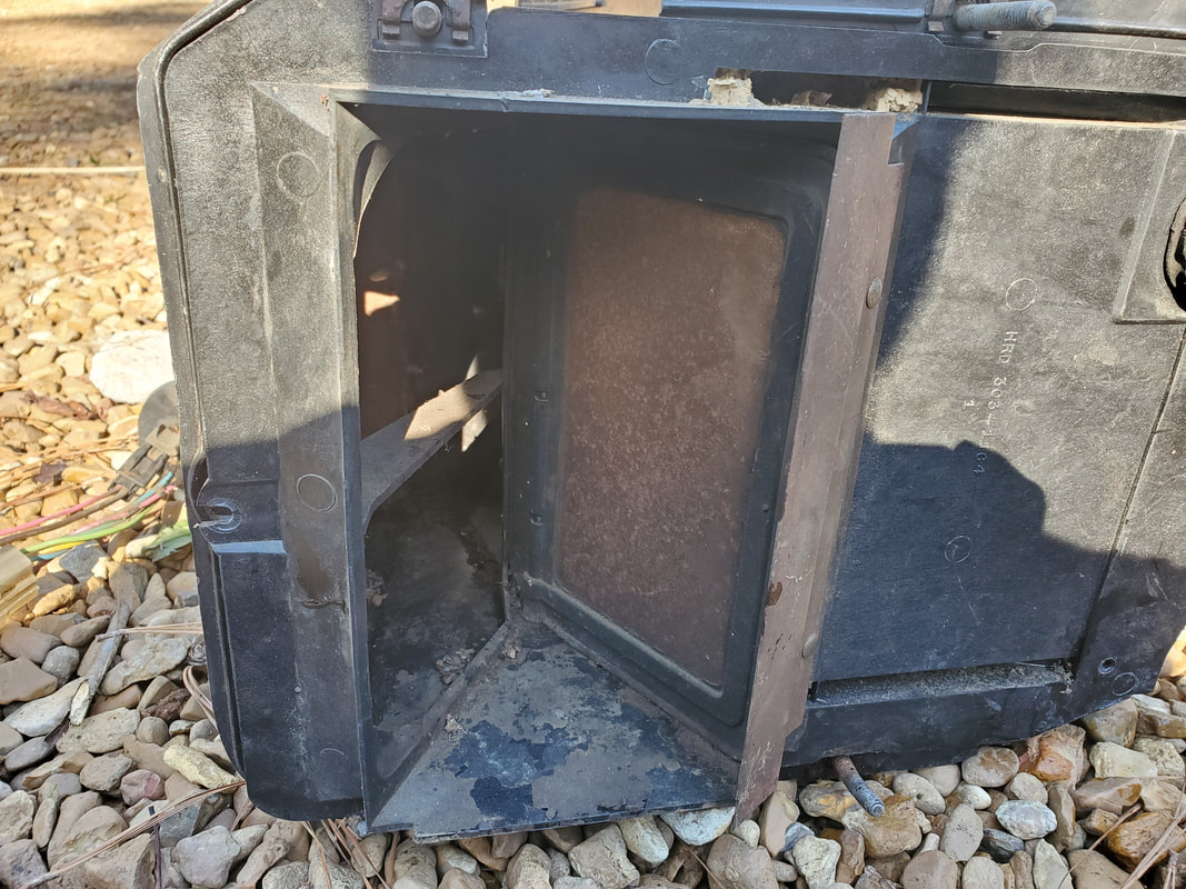 Hot/cold blend door in the closed position, closing the heater core up from the air of the blower motor. Air will pass through the AC evaporator and into the inner vents, bypassing the heater core. 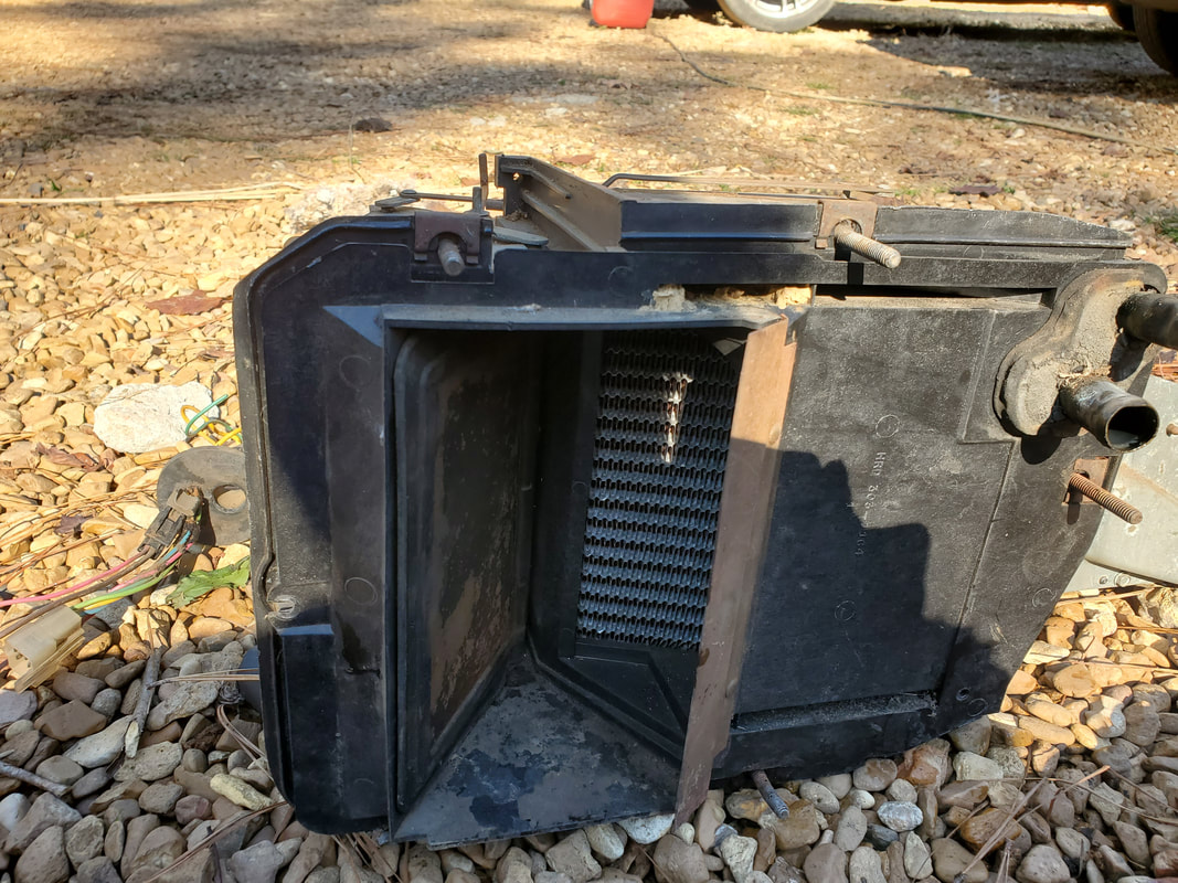 Blend door in the open position allowing full air movement into the heater core. Even though air will still move through the AC evaporator, when the AC is off, the evaporator won't get cold so it won't matter that air is allowed to pass through this component all the time. The next order of business is the blend door that regulates air movement for the floor vent and defroster. This was a pretty simple setup, just positioning the blend door in the closed position for the floor vent, leaving the defrost vent wide open. Don't forget the intermediate area just after the heater core allows for a lesser amount of air to pass over and into the defrost area. This pin up was a little more invasive with me drilling a hole in a lobe of plastic inside the air plenum, and mating with an already cut hole on the edge of the blend door. A sheet metal screw allowed for the blend door to be secured to the lobe of plastic, in the closed position. 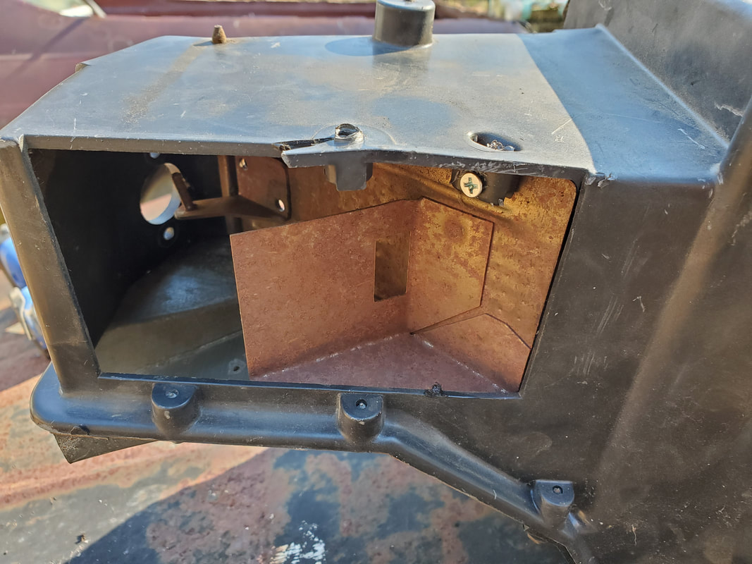 Defrost/floor blend door pinned closed with a single sheet metal screw in the upper right side, through a lobe of plastic in the air plenum. With all the blend doors addressed, I had to address the large holes that were left open after removing the vacuum actuators. This was done in a way to be reversible, for already stated reasons. I did this little patch as neatly as possible, cutting a piece of sheet metal that fit inside the cavity where the actuators sat. Two holes were drilled and filled with two screws capped with nuts, holding the whole works in place. The same thing was done for the hole from a single actuator in the plastic box. Using the already made holes from the actuator bolts, the whole patch was done in a completely neat and reversible manner. 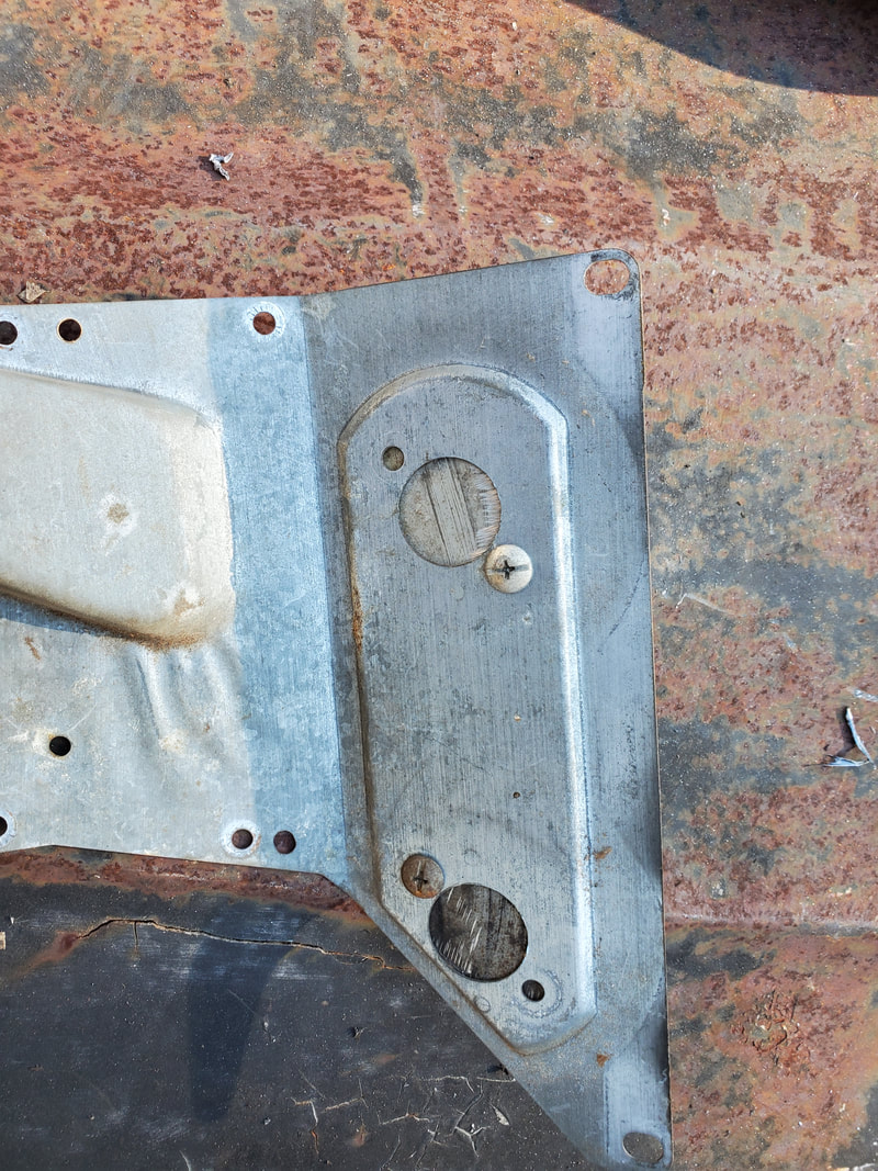 Double actuator panel with sheet metal patch bolted in place neatly. 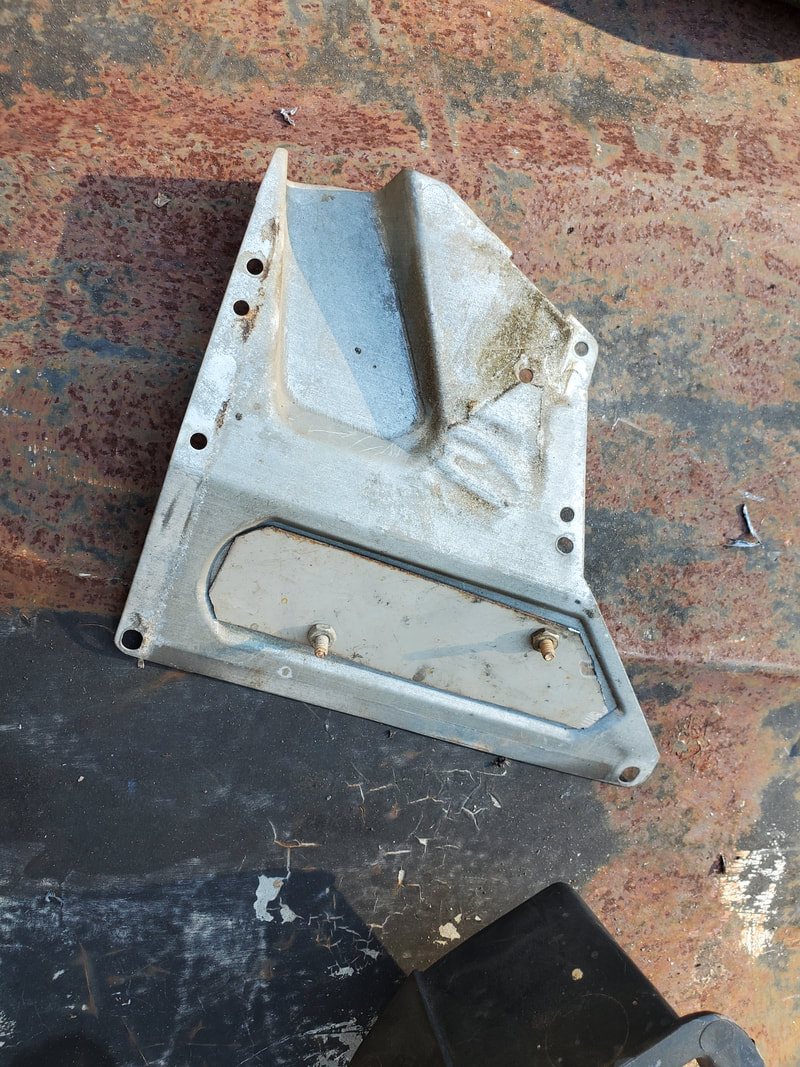 Inside showing the fitment of the sheet metal panel. 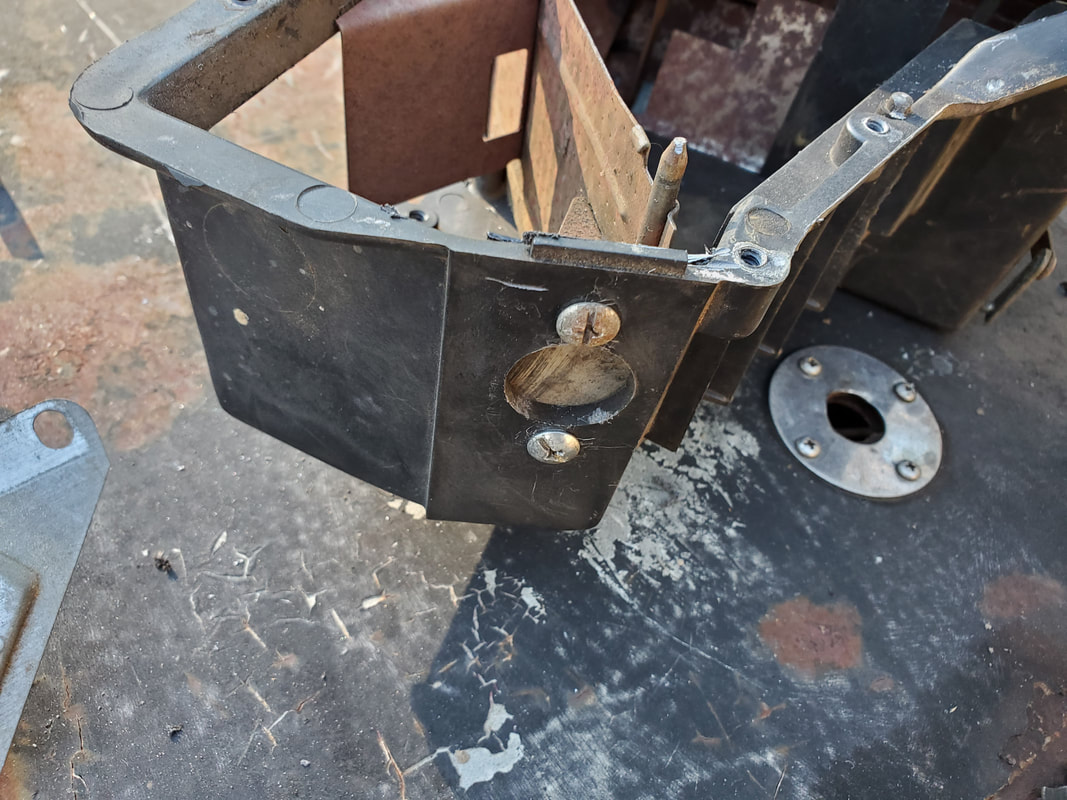 Single actuator opening with patch secured in place with bolts/nuts. 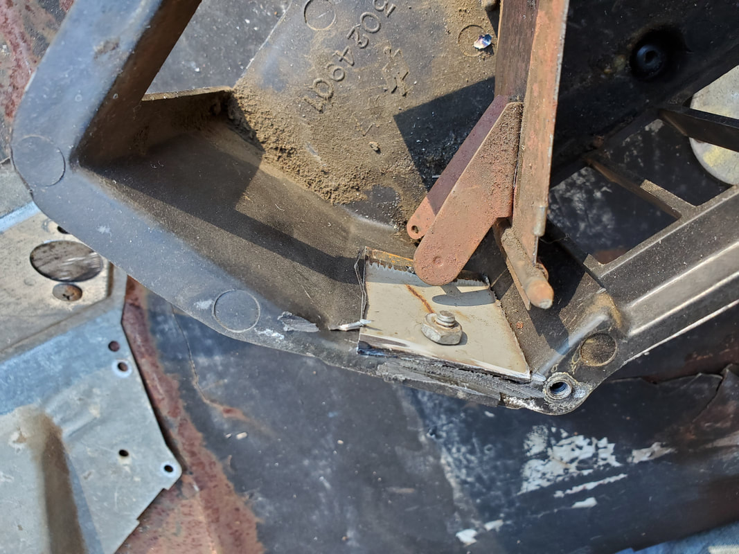 Inside of HVAC box showing small patch and nut/bolt. After making these little modifications, I was able to reassemble everything and get the inner HVAC box mounted back in place on the inside of the firewall. With both HVAC boxes secured back in their respective places, I was able to remount the fender shield and put a close on this part of the project. 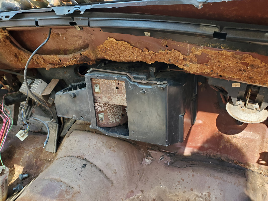 Of course to fully complete the HVAC retrofit, I will have to get the blower motor and a power line for a future AC compressor clutch wired in so the control panel can do its job of controlling those critical components of the HVAC system fully operational. Of course in order to do that I will have to take on the rewiring of the car, getting those lines properly wired. Of course I will have to fully figure out the layout of the wiring for the resistor pack as well as the switch for the blower motor. I'm sure the interwebs will have schematics showing what the different colored wires represent on the whole set up. After pulling apart the HVAC system on the Elco, the next phase was to pull apart and check the cores to make sure they at least appear to be viable. Because of the nature of the car we're dealing with, I can only imagine the replacement cost for either the heater core or evaporator will be enough for me to say "fuck it" on the HVAC system if I had to replace everything. The next thing I need to give attention to is the modification/simplification of the HVAC system. This, as stated before, involves removing most of the old controls of the system and pinning a couple of blend doors to one position so air will only move out from the defrost vent and the chest level vent. I pulled the box apart to pull the heater core out. A few bolts separated the box allowing me to easily pull the core out, and to my satisfaction spill nice green coolant everywhere. This more or less tells me that the core should be pretty good, versus if the liquid that came out was shit brown from rusty water being in there, which would've told me the core was clogged with trash. With the heater core written off as good, I moved on to the air controls. 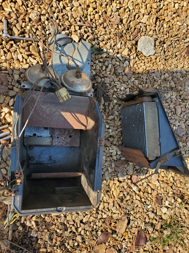 Heater box separated with the heater core pulled free to the right in the pic. 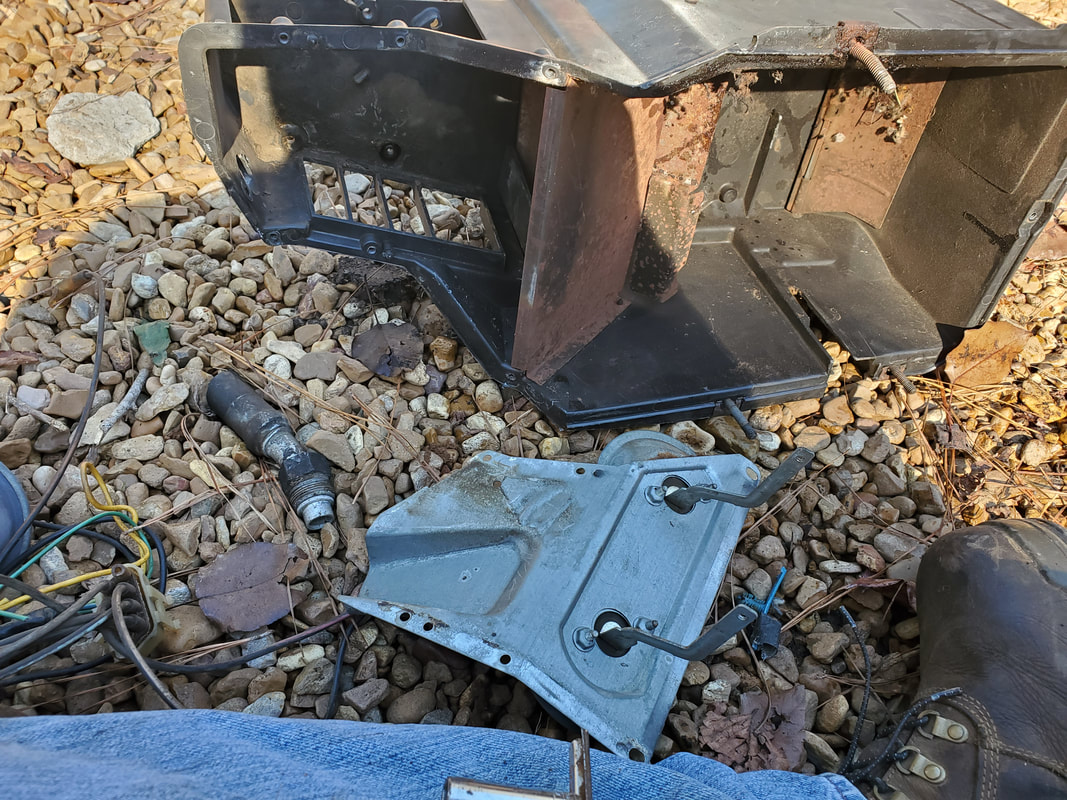 Blend door pneumatic actuator plate removed, these components will go due to those blend doors not needing to be controlled in our new configuration. One of the blend doors the pair of actuators controls is the defrost vent. Our vent will be pinned open all the way in order to keep air from moving around and down to the floor vent. The other actuator controls one half of the blend door that routes air to the chest level vents. That vent will be half pinned open and half pinned closed. In the meantime I pulled the actuators from the plate they were mounted on as I still need the plate, just not the actuators. 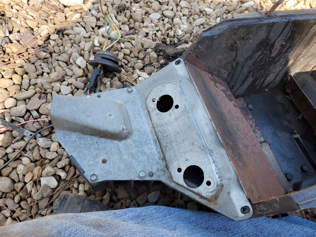 Actuators removed from plate. I will have to make some type of plate to cover these holes later on. The heater box showing the positions of the blend doors as they will be secured. The left vent is the defrost, with the vent in the down position to only allow air to pass up through the vent. The blend door to the right is the 2 piece door, with the top closed to help regulate the amount of air that would pass through the chest level vents vs the defrost. The bottom half of this blend door is pinned back, blocking some of the passage of air into the defrost vent. Because the heater core is placed where half of it is in the path of the defrost vent and half is in the path of the chest level vent, putting the blend doors where they're at will actually regulate the amount of AC that is allowed to pass around and up to the defrost vent while still allowing most of the heater air to move through to both the defrost and chest level heater. Bottom half of blend door that controls heat to the chest level vents or the floor level and defroster. The only blend door control that is going to be retained in this simplified system is that of the hot/cold selector blend door. Especially since the blend door is cable actuated, this already vital control will be kept as is. This vent and its cable will be hooked back up to the HVAC control panel in order to restore its operation. Blend door in the setting to call for heat as can be seen by the exposed heater core. This opening is where the outer box blows air into the inner box to distribute it through the vent system. Blend door in the position to only allow AC to pass over it and into the inner HVAC box. Note how blend door hides the heater core. With the battle plan mapped out for the blend doors, the next move will be time to get the doors pinned to their positions so we can start getting some of this stuff back together. Once we get both HVAC boxes installed we can then move on to the electrical system. Recently we made an arrangement with an old coworker of mine to work on an old truck he had sitting along side his house for the last eight years. That truck is a 1980 Ford F100 long bed pickup. I will showcase that vehicle in another article but in the meantime I will focus on the next vehicle we picked up from him. After bringing the F100, nicknamed the DOB for Dirty Old Bastard, we also had claim to an early 90s GMC Safari minivan that he also had along side his house, behind the DOB. Now you may wonder WTF do I want with this vehicle? Well the main reason, actually two reasons is first, I want the powertrain from this van. The van has a 4.3L V6 with a 1st gen 4L60 auto transmission. Both components are relatively low mileage as our friend had them swapped out sometime before parking the vehicle so they still have plenty of life left in them. My plan is to drop this powertrain in the 46 Ford, since its on an S10 frame, this powertrain should slide right in. Second reason is that I want the rolling chassis. Since this is a wide wheelbase van, and after measuring the length of the wheelbase, it was only a few inches shy of being a perfect fit for the 51 Chevy Suburban body. I figure that I can put the 51 Chevy on this chassis with only some small variations, allowing me to have that old body on a more modern chassis that I can work with, for the same reasons as the 65 Mustang and the 46 Ford will have more appeal. Until then though, the main reason is to get the powertrain out. 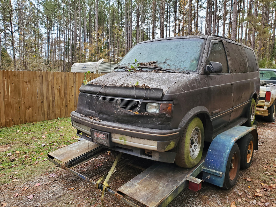 The van on the car trailer after we made it back home, with the trusty F250 dragging it along. 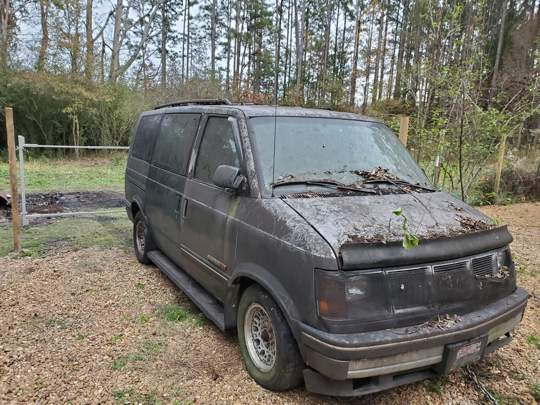 We had to roll the van off the car trailer then use our neighbor's tractor to drag the van over to this parking spot in the midway of the yard. I will pull the engine at this spot, then be able to pull the van backwards around the east side of the yard around to where I would set up the dog house, on the southeast corner of the fenced in yard. Of course this van is a biohazard due to it sitting longer than the DOB did, so mold and mildew are abundant throughout the interior. I will have to gut the interior as much as possible, of course trying to sell what I can at salvage prices just to move the parts as I remove them. I would at least like to cash out on some of these parts versus just scrapping everything that I'm not keeping. I may hang on to the seats if they appear to be a good fit for the 46 Ford or even the Elco. 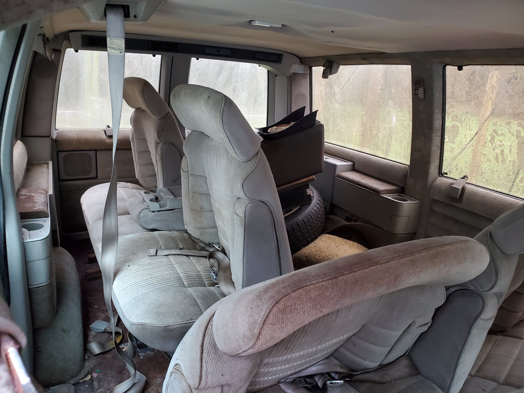 Seats for van stacked in the back, not mounted, hopefully I can do something with these seats short of selling or scrapping them. Its amazing how engineers would decide to try and cram an engine in the tight quarters that's present under the little hood of this van. It looks like it would be a nightmare to work on for just about everything. At first I was afraid I might have to literally chop the front off the van in order to get the engine crane in there to pull the engine and transmission straight out. After a thorough examination, I found that the substructure in the front is made to be removed after pulling the radiator, grille and other components out. I can remove these sections of the substructure and it will open things up enough to be able to pull the powertrain straight out. 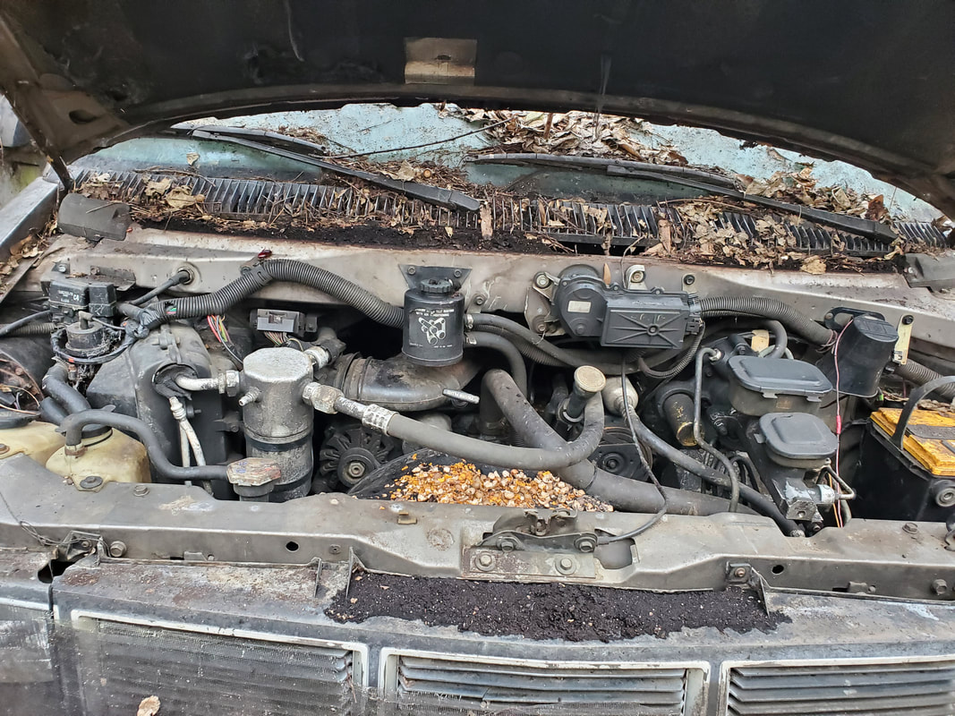 The tight quarters of the van's engine bay, this is ridiculous! I did have a wild plan for the rest of the body of the van though. After stripping everything and even pulling the body free from the frame, I thought about using the body as the basis of a doghouse. Just like with the car chicken coops, I could make a dog house with the body. Since the body wouldn't be on a rolling chassis, I would mount it on a foundation like a small shed. I can build the body up like I did with the chicken coops, with light, plumbing to feed an automatic watering dish, even build a bulk feeder that can be reloaded from the outside and feed the dog on the inside. If I get a good power feed to the doghouse I can also install a cheap window AC unit and space heater for climate control so the dogs can go in the doghouse in comfort. This is worth considering since this would allow us to leave the dogs in the fenced in confines of the yard, knowing they will have a comfortable shelter to go into where our caretaker would only have to verify the feeder is topped off since they'll have water and free reign of the yard in which to relieve themselves. |
