|
Today we pretty much have what would be considered a wild card day. Sometimes things work out this way where one finds themselves bouncing around from one project to another, doing a little here and a little there, not really focusing on any one thing. The first episode starts with the Scion's AC not working the previous day. Thinking this would be a routine check to see if the system may have just went down normally, as is the case with old systems with bad seals and all. After adding some stop leak, as a normal measure, then starting to add some refrigerant, as the system started flowing the cool stuff through, I found exactly what was happening. One of the metal lines had a pinhole in it, which became known when the coolant started flowing through that side of the system. 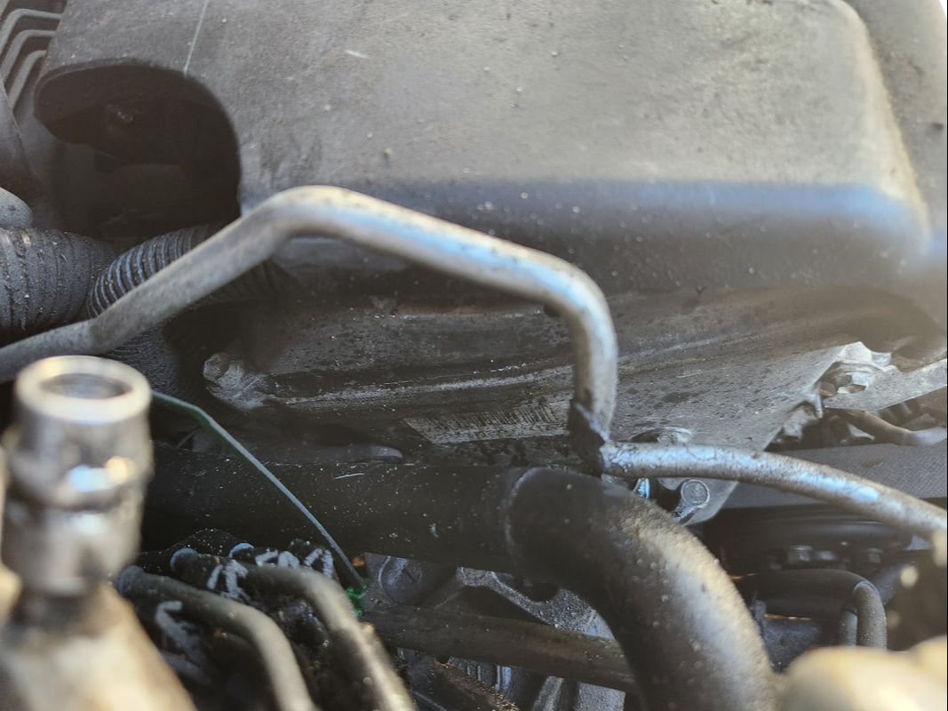 The AC line on the Scion with the pinhole leak in it, right where it makes contact with the power steering reservoir hose, luckily this wasn't compromised as well. This pretty much put this little task to a standstill. I couldn't even remove the metal line as there was a plastic fitting covering the junction which requires a special tool specific to Toyota systems. Step one will be just getting the metal line off. Then, I have to actually source this thing, whether from the junkyard or online. With that at a standstill, I moved on to Truckstang, correcting the issue I had with the oil pressure gauge and sending unit. This involved assembling some plumbing fittings in order to bring the sending unit out from the block and the tight quarters that prevented me from being able to use the piece in the same way as the old unit. With teflon tape and tools, I assembled the ensemble and secured the piece in place where the old sending unit was located. With the new setup done, I just had to clip off the wire after the inline resistor and add a crimp terminal to clamp to the new sending unit terminal. The whole job was quick and easy to do. 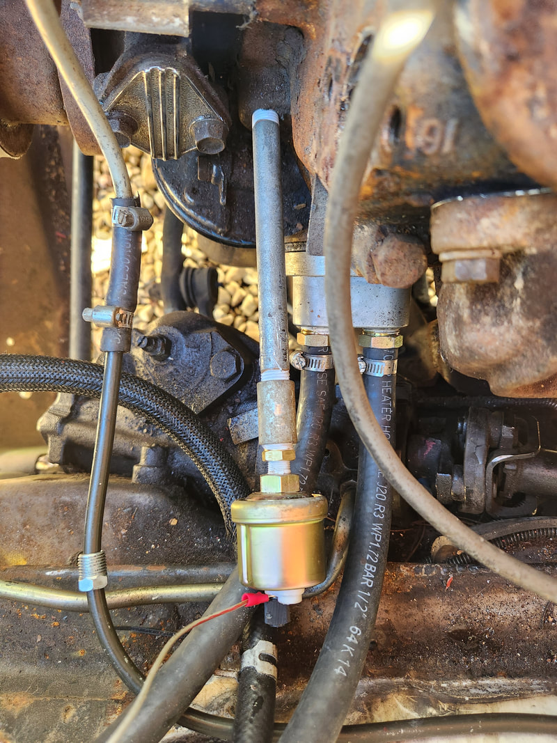 The new oil pressure sending unit attached to the plumbing pipe fitting arrangement to bring it out from the side of the block. Note the wire that's hooked up to the unit, trimmed down from the length of wire that had the inline resistor. With the little bit of work done on the Truckstang out of the way, I moved on to the Rustang, picking back up with a little bit of fitting regarding the lawn mower carb project. This time, I wanted to fit the gallon fuel can and metal lines that would connect to the fuel pump and carburetor. I ended up having to remove the horn bracket assembly since it was mounted on the driver's side. I remounted the unit on the passenger side and added extra wire to connect the horn back to its relay and ground wires. 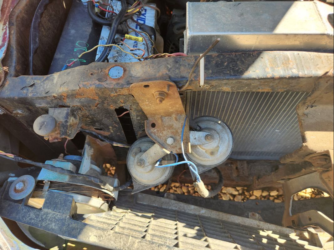 The horn bracket and assembly remounted on the passenger side, out of the way. With the horn cleared from the area, I fit the fuel can in place and bend a section of metal line so I can test fit the setup I'm trying to build. I will have to drill a couple holes in the fuel can and probably use some JB weld or something on the order of that to seal the tubes in the top of the fuel can. I still have to figure out how to secure the can in place. Also, I'll need to add some lengths of rubber hose to connect the input side to the fuel pump to the metal line going to the fuel can. I'll be a pretty simple and bootleg kind of arrangement, especially since this is temporary and just for the sake of testing MPG more so than actually doing a whole new setup. 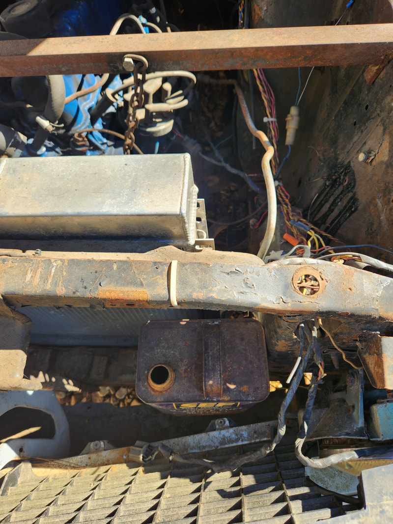 The metal fuel can set in the spot where it will be temporarily hung, along with the metal line that will be connected to it and the mechanical fuel pump further back. Once I do my tuning and testing to get the kind of readings I hope to get with this setup, I'll hook everything back up like normal, and do some more testing with the idea of setting up what could be a viable long term setup for this vehicle, or any vehicle for that matter. Being able to arrange a setup that can hold up to the rigors of automotive operation while still delivering the performance I hope to achieve would put us in a position to further show how this is a viable means of operating an engine in an economical manner, above and beyond the old school 1 and 2 bbl carburetors that used to be used on larger engines in the past.
0 Comments
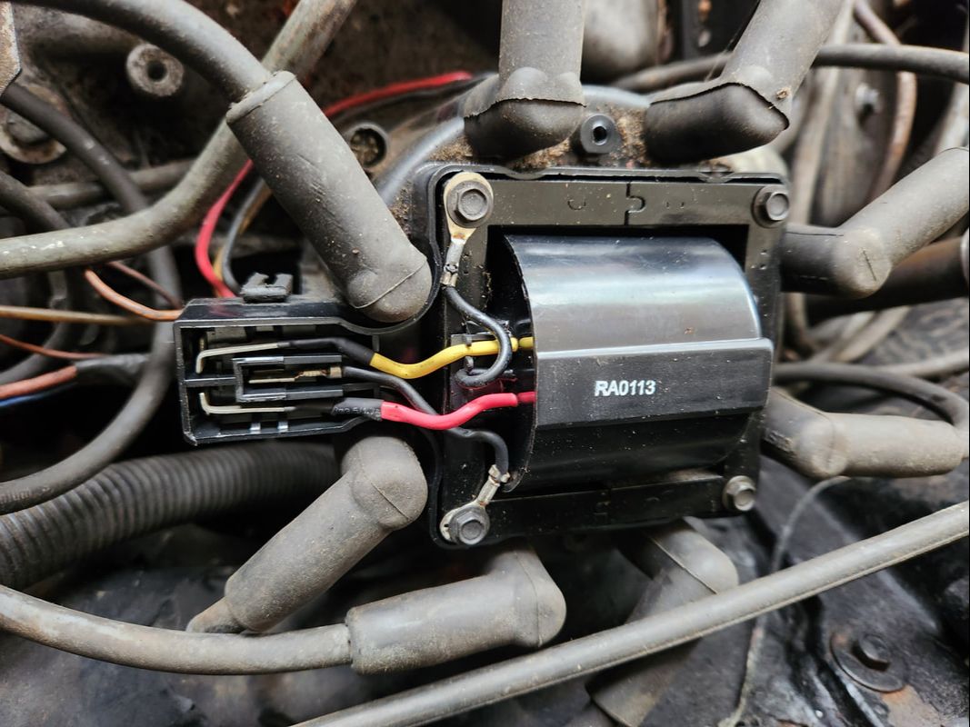
After the success of making the Rustang run on the makeshift lawn mower carb intake and carburetor, I had already started planning my next part of the project. There's little things I wanted to do to make the setup more user friendly, as well as be able to test out the performance of this setup. What I planned on was installing an O2 sensor and air/fuel gauge to meter the A/F ratio to be able to see how the mower carb setup is tuned. The next thing is a choke cable, so I can cycle the clutch from inside the cab. The next part is a one gallon fuel can that will be used for testing MPG by seeing how far I can go on one gallon of fuel, pretty simple. An add on that I'll also add that was suggested by another Youtuber was the addition of a fuel bypass and return line in place of the regulator. The mechanical fuel pump would pump most of the pressurized fuel right back to the tank, with some bled off to feed the mower carb. The pressure will be plenty low enough that it won't blow any gaskets or flood out the carb/intake. 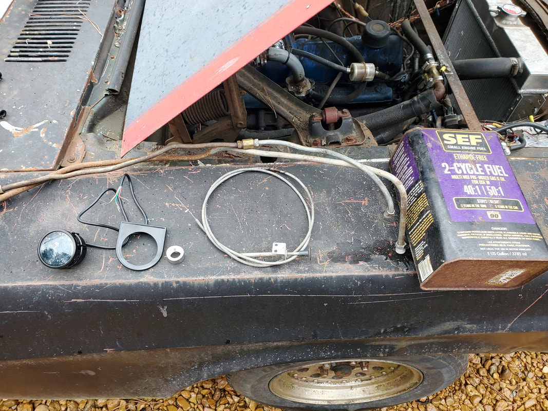 The batch of new parts that have to be installed to further complete this conversion and set the vehicle up for road testing. A/F gauge and mount, O2 sensor bung for exhaust pipe, choke cable, fuel can and a couple metal fuel lines are laid out pending installation. The first thing that I worked on was installing the choke cable. I found a spot on the firewall that was more to the driver's side to fish the cable through, then flexed the cable around to get it where its pointing straight towards the choke lever on the carb. I used a combination of zip ties to hold the end of the cable on the soup can air cleaner and one of the extra choke cable brackets, held in place with a sheet metal screw to the firewall, to secure the cable fully. The knob end in the cab was secured under the dash at a point where a screw was present that was holding a trim panel piece. I tested out the cable to verify that it would cycle the choke properly, so with that done, I can move on to the fuel system. 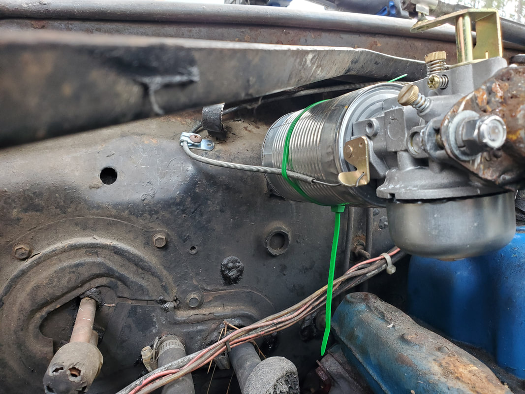 The choke cable secured in place with zip ties and a bracket at the soup can air cleaner and on the firewall respectively. 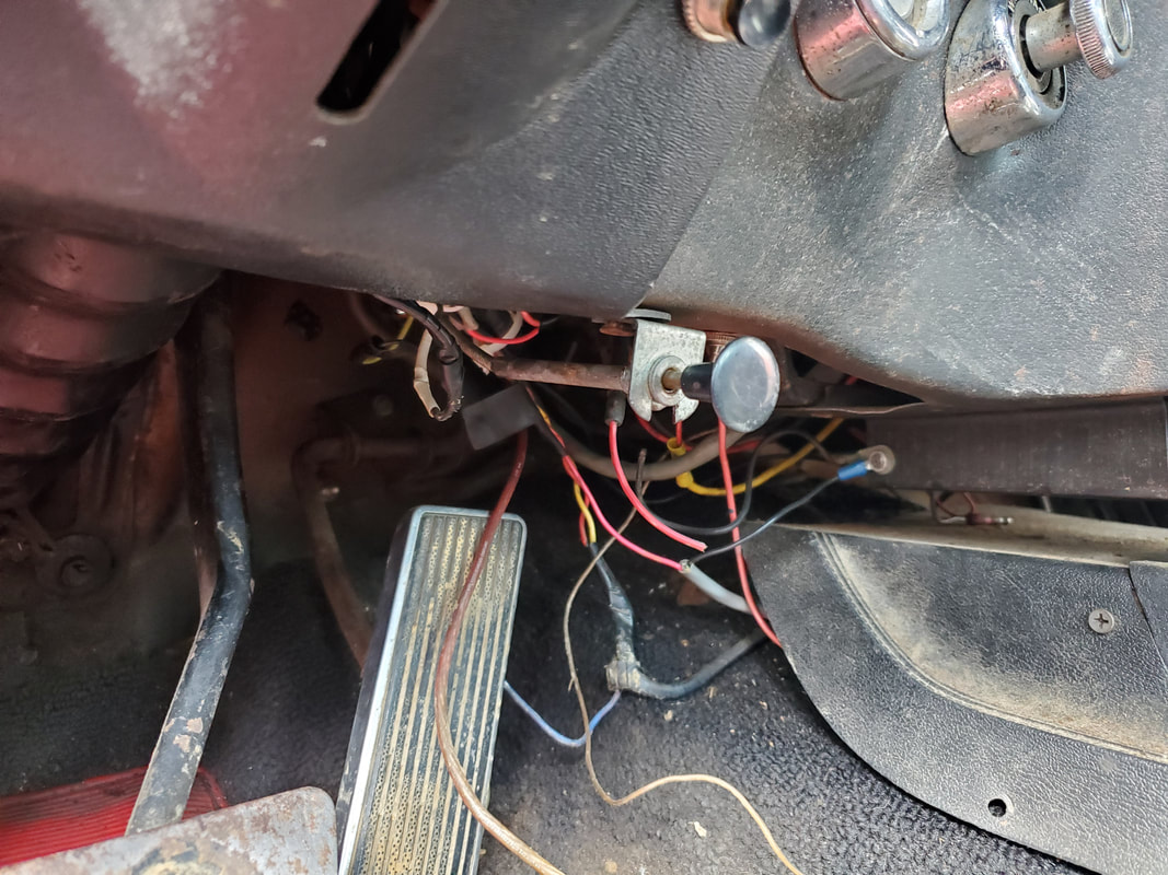 The knob end of the choke cable mounted under the dash. The next move now is plumbing the gallon fuel can. After disconnecting the main fuel line from the pump, some salvaged metal line was manipulated to connect to the input line on the pump. As is always the case with things, things break. Sometimes they break at the most inconvenient time, then sometimes the thing that breaks is something that can't necessarily be repaired easily, if at all. Such is the case with the horn on the Tracker. As was the case with the old Tracker, the horn button is built into the airbag assembly and is not going to just be replaced like any other switch. We're not exactly going to buy a whole airbag just to replace the switch either. As was the case with the old Tracker, a switch was rigged up to power the horn in place of the button on the airbag at the middle of the steering wheel. 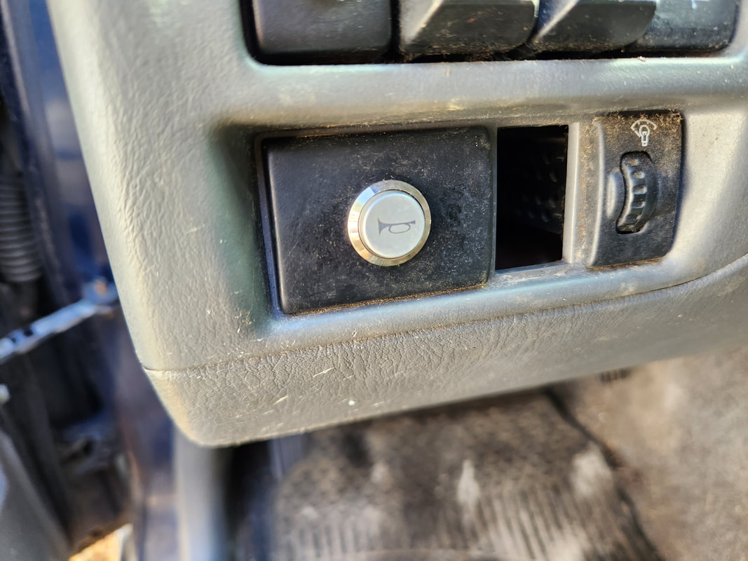 The universal horn button installed in a panel piece on the dash. When I scrapped the old Tracker, I pulled several parts from the vehicle. One of those pieces was the old horn button I installed to repair that broken horn switch. I saved this just in case I would need to make this makeshift repair once again. Well here we are once again. I drilled a hole in a small panel piece that fills one of the spots that would've been used for a factory switch for some other accessory. The switch went in the hole and was secured with a nut. The next thing was to run a couple wires through the firewall to where the horn is located. I cut the wire that was feeding the horns, then removed the long length of wire that was connected to the plug on the passenger side of the engine bay. I removed a plastic plug from a hole in the firewall and drilled a small hole in the middle of it to run the wires through. One wire was short and spliced to the wire for the horns and capped with a narrow female terminal to be plugged to a terminal on the switch. 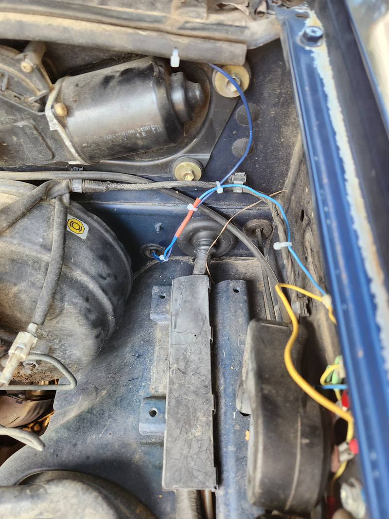 The pair of blue wires routed through the plastic cap in the firewall to the horn switch. Note how one wire goes to the horns and the other up to the top along the firewall. The other wire was capped with another narrow female terminal and plugged to the other terminal on the switch and with both wires run through the hole in the plastic cap, the second wire was routed along the top of the firewall over to the battery. From here the end of the wire was terminated with an inline fuse and capped with a large ring terminal, which would be connected to the battery terminal directly. I ended up drilling several small holes along this rubber cap piece, in order to use zip ties to hold the wire, recessed inside the cap piece along the top of the lip over the firewall. I removed the bolt from the battery terminal, inserting it through the ring terminal and putting the whole works back onto the battery terminal, tightening everything up. With that, the horn had its own separate circuit and was working as designed. 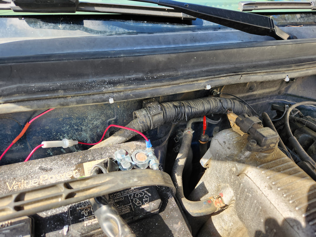 The battery terminal with the ring terminal and inline fuse hooked up, along with the power feed wire routed along the weather stripping piece, secured with zip ties through drilled holes. All of this is temporary of course. If there's a chance of repairing the original problem, then this arrangement wouldn't be needed anymore. At the same time, we had another unexpected surprise. After hearing sounds coming from under the house of chickens, baby chickens, we went to investigate, only to find a hen with several chicks nestled inside the insulation. Having made its way in from an open spot in the insulation sheeting, the hen laid a nest and hatched several chicks. Well, we had to slide under the house and cut away more of the already messed up insulation layer to access the chickens, with the hen being a dissenting participant in this ordeal. Once the chicks were recovered, we had to set up another brooder box so we can raise these birds to maturity to add to the flock.  The batch of chicks harvested from under the house and set up in a makeshift brooder box to raise them up. We have the incubator set up with even more eggs that appear to have been fertilized and were being set on by another hen. We'll see how those eggs turn out as well. Maybe we'll end up with more birds. If that batch hatches, we'll definitely have a good batch of birds for this year without even having to buy them, which is literally what this whole hobby is all about. Let's hope these birds keep up with the egg and bird production like the machines they are. During the first attempt to start the engine, I found that the starter was cranking the engine weakly. First thought was the starter may have been old, so I swapped it out. When this proved itself to be in vain, I swapped out the starter again with one more unit I had in stock. This proved itself to be a vain attempt as it too cranked the engine slowly, up to the point the battery couldn't handle the load even with the jump starter in place. 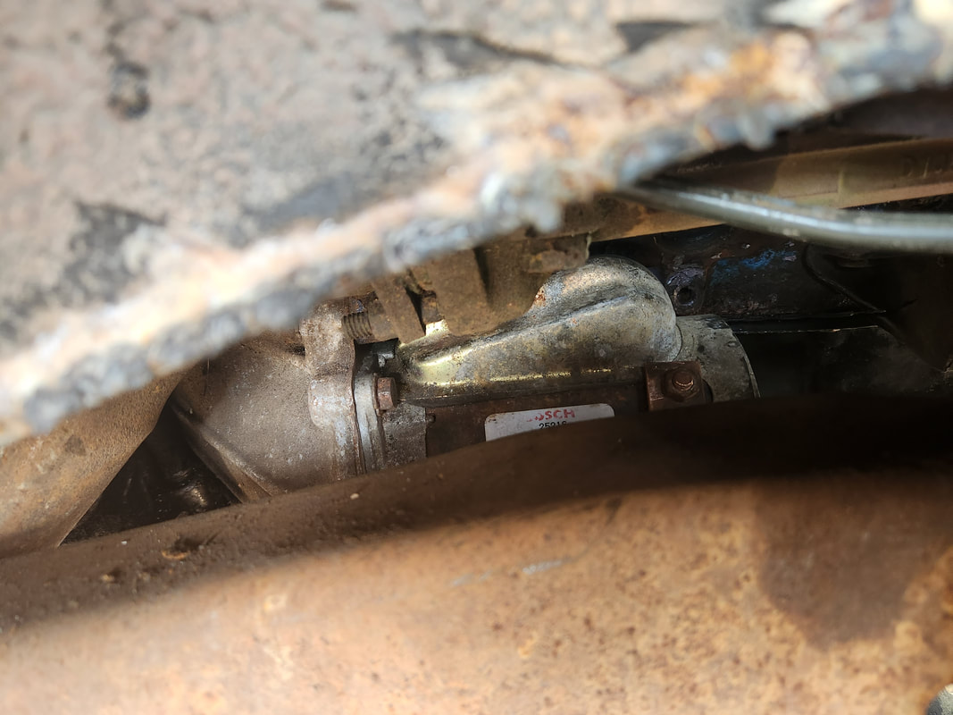 The third starter installed in an attempt to see why this engine is being turned so slow. At this point I turned my attention back to the battery. I swapped out the smaller battery with the slightly larger unit from the FMT, but I had to turn the battery 90 degrees so the terminals wouldn't touch the side walls. The battery wouldn't be sitting in the tray, but it'll be stationary enough that it won't fall into the engine while its running, hopefully. The next several attempts to start the engine were met with failure once again, except for one moment when the engine sputtered and backfired in a brief second. 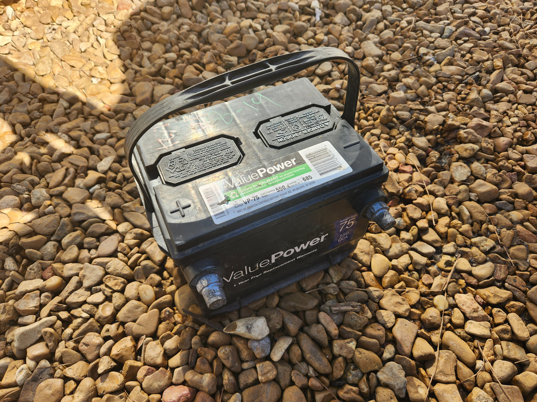 The old side post battery removed due to its not having the CCA to handle the starter on this tight engine. Even though under normal circumstances this battery would've worked, but these are not normal circumstances... 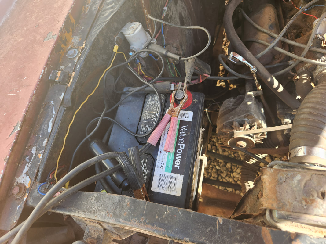 The FMT's top post batter staged side ways to fit well enough so the terminals won't make contact with any metal. At this point I started turning my attention to the ignition system. I set TDC and rearranged the wires again, hoping to see if maybe I was off on the initial timing. That was no good either. I even tried clocking the wires 180 degrees in case I was off during the initial timing, again, something that can be easy to do in this process. That proved to not be the case. So, once more I did another TDC setting then placed the wires back and hooked up the timing light. I wasn't getting any spark. At this point I turned my attention to the aged components of the Duraspark ignition system. 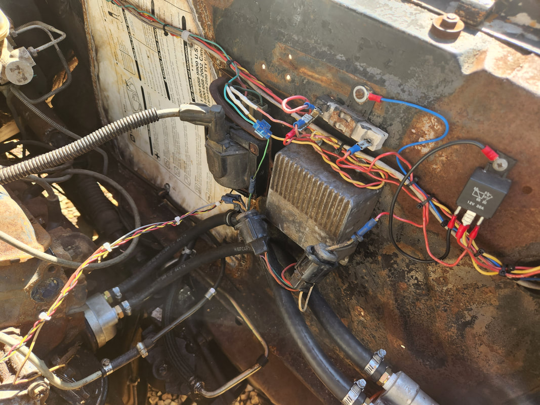 Ignition system components on the side panel, showing the clutter present with this stuff. Once can also understand how the potential for failures is high here. What I ended up noticing after metering everything was that the ignition system was the source of a fair voltage drop on the entire electrical system. The components were rather warm to the touch. With the battery in a weakened state, the ignition system pulled the system voltage down to mid 11's, while the USB dongle in the 12v receptacle, which is independent of the rest of the car's system and goes to the battery, showed 12.1v. Unplugging the line feeding the ballast resistor made the system voltage bounce up to 12v just as well. At this point I changed out the ignition module as I did have one more of those left on hand, and that was the spare in the Rustang's parts box. Another cranking attempt had spark this time, but not for long, after a couple episodes where it looked like the engine might try to do something the engine dragged the battery back down to where it wasn't cranking enough to do anything. Now, I checked the ignition system once again, and I lost spark yep, once again. It was at this point I pretty much came to the conclusion that Duraspark has to go. 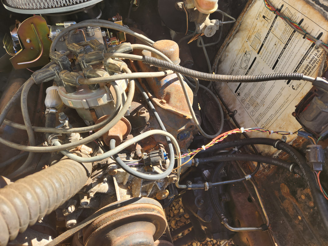 The Duraspark distributor with the wiring harness strung across the engine to the left side wall where the other ignition components are located. What a mess. It's not that I don't like the Duraspark system, I cut my teeth on this system when I migrated from points ignition and would scour junkyards pulling parts from older trucks and cars to source all the parts to assemble whole systems in the Mustangs. But as we fast forward to now, most of this stuff is old, corroded and just blah. Plus with advances in the aftermarket, namely the GM style HEI distributors made for Ford and Chrysler engines, it only makes sense to just upgrade to this distributor. It will completely clean up the engine bay and eliminate all the extra components and wiring that are currently in place. The coil, ballast resistor, ignition module and many feet of wires would all be gone, save for the one power wire feeding power to the cap and another for the tach if I add one. That will mean less junctions for wire terminals to go bad and everything is pretty much readily available, the HEI modules are cheap on line and not too horrifying at the parts store. This is the same system on the FMT and it works just fine. Another issue that has to be noted is the fact that this engine is tight as hell. This engine was rebuilt back in 2006 and only run maybe once or twice for not even a total of an hour's worth of time so for all intents this engine is not even broken in. Add to that the fact the engine sat since then so for over 15 years this engine sat idle. It will take a heavy starter to really crank this thing over enough to get some RPM's going and that also means the battery required will have to be a heavy hitter battery able to deliver the CCA to give the endurance necessary to keep spinning the engine until it starts. Getting an ignition system that will fire hot and true will go a long way as well since even with the slow cranking as long as we can get fire, we can hopefully induce a firing to get the engine to start up and work at loosening itself up. All this means is as we get closer, we still end up being still far off from being done. Never fails. Next step get an HEI distributor.
When we left off, we had an issue getting fuel up to the carburetor to verify that things would be ready to rock and roll on the startup. I ended up pulling the fuel pump from the Dodge and installing it, only to get the same symptoms. I finally checked the last spot I ever thought to check, the short section of fuel line coming from the side wall going up to the carburetor. This piece of metal line is an older piece that I never thought might have a problem, but it did. It had a small dirt clod inside it that was easily cleared with a pick. Once this was done, I immediately got fuel up to the carb in force. Now, the older fuel pump might've been fine if I cleared this plug beforehand, but it's all good, it's not like I'm throwing the pump out, it just went on the shelf with all the other spare parts to be used later. Either way, we have fuel now.
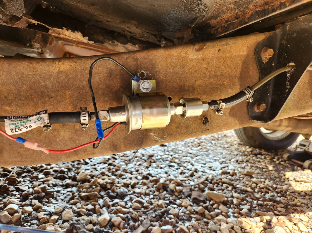
The fuel pump pulled from the dodge, which has an integrated filter, installed in place of the other pump. This type of pump should've been used in the first place to ensure that any garbage pulled from the tank gets caught before it can compromise the pump.
The first attempt to crank had me immediately installing the timing light on the coil wire to check for spark. After seeing there was no spark, I put a meter on all the different points on the ignition system, verifying power, then reseating a few connections on the ignition module and the ballast resistor. After doing this, I had spark at the cap so that was good. Now, it was time to try to start the engine. After a few attempts to crank, it was apparent that the engine wasn't spinning as fast as I've seen SBF V8's spin. I had the battery charger on, with the jump start setting engaged as well. It just seemed that the battery was draining way faster, even with the jumpstart engaged. This could mean a couple of things. One, the battery could just be weak, it is a used junkyard battery and that doesn't say much. The other is the starter might be bad, especially since this thing was on the engine since I last rebuilt it back in 2006, probably before that. So, I installed a load tester on the battery, even though the charger was still engaged. This couldn't possibly be accurate as the juice from the charger was offsetting the load testers draw on the battery, even if the battery was weak. I'll have to check that again later w/o the charger. Instead, I pulled the starter and swapped it out with one of the spare units I had in the Storage Trailer. 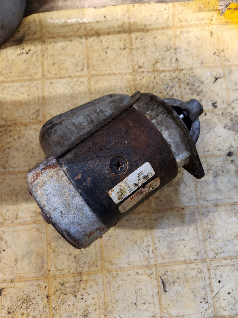
The old starter that was on this engine that is at least 15 years old but more than likely older than that.
After swapping the starters out, I tried again, this time with the same results. The system appeared to not take long before it drew the battery down. At the same time the starter solenoid even started smoking. So, my next move was to replace the solenoid, maybe this unit was old and the contacts inside were rusty or corroded and not conducting at its fullest. I went ahead and swapped this unit out with the last unit I had that was still in plastic, despite it too being old stock, which sometimes doesn't say much. This attempt to start still netted the same result. At some point I did start getting some weak sputters when I had the distributor clocked all the way clockwise as far as it could go. I attempted to clock the wires clockwise to simulate rotating the distributor more, but that didn't work either. I'm still not 100% sure if the distributor is 180 degrees out of time, which is sometimes easy to do when doing the initial timing of the distributor. 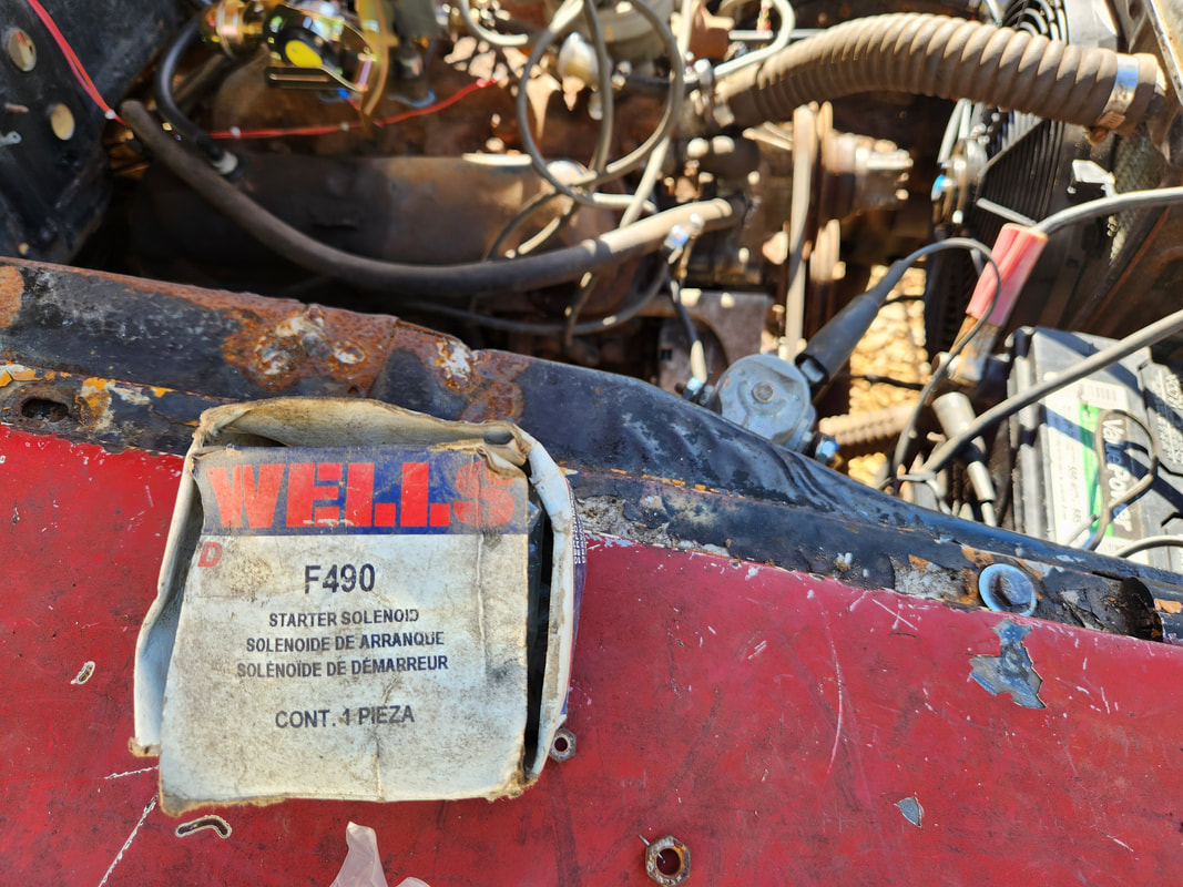
NOS solenoid pulled from inventory to replace the solenoid previously installed on the car.
Even with all these theories, the whole damned problem might be that I'm not getting enough power to the ignition system to even attempt to fire the damned thing. I will have to check the battery one more time and for shits and giggles maybe even take the starters to be checked just to verify they're good or bad. I need to verify these things to determine whether I'll need to source a good hot battery or starter or both, for that matter. This is what we have to deal with when we try to use used garbage, whether NOS or stuff salvaged from another source. In a perfect world, builds like this would be done with all new parts from the smallest pieces all the way up to things like batteries and even to a lesser degree, engines. I've seen guys resurrect engines that have sat for 20+ years and have even been somewhat frozen to some degree so there's no reason this one should not fire. I just have to make sure all conditions are met to ensure startup. More to come...
It seems like the closer you get to getting a project to completion, the more things seem to slow down. All the large stuff that typically gets done in the course of building something like this is all done, and if one isn't sharp, they will end up with a million little bitty bullshit tasks that need to get done before the project can be considered ready to roll in some form or another. This is the case with Truckstang. Technically, everything is ready in order to crank the engine, and even with the driveshaft in, the car can even be engaged to try and see how it acts in motion, even at a walking pace. Of course, to engage the transmission it needs oil. There's only a minor problem, the transmission needs a speedometer cable installed as the large hole on the side of the tail shaft will keep oil from staying where I want it. A quick trip to the junkyard remedied this and, in a few minutes, a new old replacement cable was plugged up to the tranny and gauge panel and bolted in place. One minor thing done.
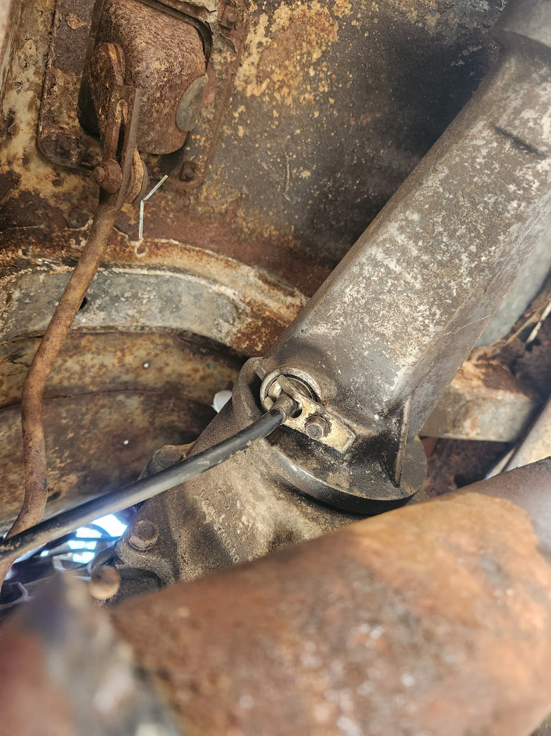
The transmission with the speedometer cable plugged in place, ready to rock and roll.
Next thing I wanted to address was the fact that I needed an oil pressure gauge in place so when I do run the engine, I can at least see if the engine is making oil pressure. This is important as not knowing if the engine is getting oil all about is a quick way to put an end to a project that was moving along pretty fast. The last thing we need to do is spin a bearing or collapse a lifter due to lack of oil. At the same time I got a voltmeter, since the only way to tell what the electrical system was doing was with the USB charger dongle that has a built in voltmeter. This is fine but the 12v receptacle is always powered and for all intents, this is a po' man's way of getting this vital piece of info. So to fill the two open slots on the gauge panel under the dash, we'll be installing a voltmeter and oil pressure meter. 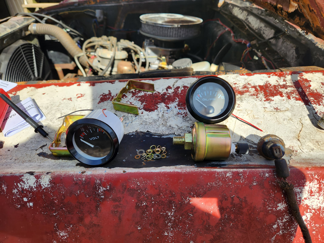
The new oil pressure and volt gauges ordered online to be installed in Truckstang.
I did run into a minor speed bump with the installation of the oil pressure gauge. The sending unit that came with the gauge is fatter than the stock unit that's currently in place. To remedy this I would have to add a pipe nipple, specifically a 1/4" NPT nipple that reaches out from the side of the block. A coupling on the end of the nipple and a 1/4"-1/8" NPT reducer bushing would then be added to screw in the new sending unit, placing it out from the tight quarters of the side of the engine block. At this very moment, the only option is to reuse the old sending unit. The next problem is the resistance of the two sending units. The stock unit ohm'd out at 100 ohms and the new one at near 200 ohms. I decided to add a resistor in series with the wire connecting to the old sending unit, and connecting a length of wire to the other end of that resistor. This wire would go to the meter. The resistance after the added resistor put the circuit at 200 ohms. Now, I'm not sure if this is going to read properly or not, but it's worth a try. And in the worst case scenario, just the idea of seeing movement on the meter is enough to satisfy me that the engine is doing what its supposed to do. If I see a good swing on the psi scale, I can at least be satisfied that the engine is making oil pressure. 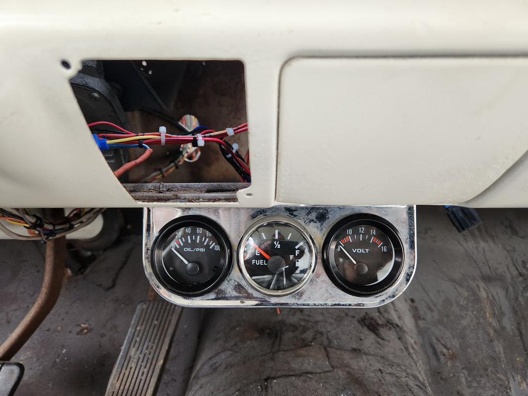
The triple gauge panel completed with all the gauges in place hooked up and ready to rock and roll.
After wiring in the gauges, I applied power to make sure all this garbage worked. Of course with the cooling fan coming on, along with the fuel pump, in standby, the voltage dropped to around 11v. The standby voltage was 12.4 at the moment. Mind you, this is a used battery so I'll have to keep an eye on this and if this proves to be a problem, I'll have to exchange this used old battery at the yard for another one before the warrantee expires. While satisfied that the gauges responded, which means the voltmeter read near 10v, since system voltage dropped, and the fuel gauge read at a level that who knows if its accurate as I mated foreign shit together, and the oil pressure gauge in standby showed 20psi. While this is a little kooky, if when the engine is running the pressure jumps up to 40+ at idle, I'll be very satisfied that the engine is healthy. Another little thing that I took care of just because was removing the power steering pump and bracket. Since I have to have custom hoses made, having the pump in place, even with the belt off, will just add unnecessary clutter in the engine bay. I may have to cap off the ports on the steering gearbox just to keep it from running dry, but if things seem to be manageable without the pump, I will forego the pump for the foreseeable future until I can source the tools and fittings to make my own high pressure/hydraulic hoses versus outsourcing this work. 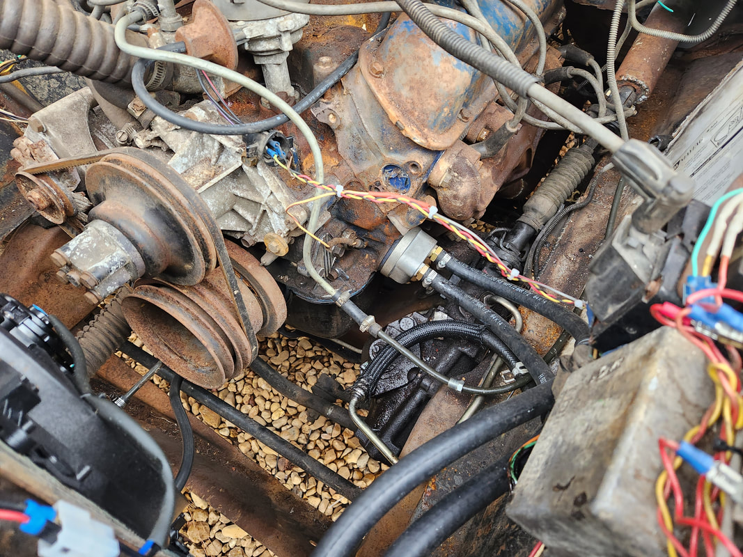
It's a little less cluttered in the engine bay without the power steering pump in place.
One more thing I had to do before I can even think about attempting a startup was to make sure fuel would get to the engine. While turning the system on, I waited for the pump to move fuel to the carb. When nothing happened, I pulled the hoses from the pump, still got nothing. I tried to manually draw fuel from the pump to no avail. I ended up pulling the pickup unit and having to blow out the tube of clogged dirt so fuel would be drawn from the tank. Once that was addressed I tried the circuit again. The next problem that was encountered was the simple fact that the fuel pump I used is a weaksauce pump that really would only work if the pump was right on top of the fuel source, like how my portable fuel source is set up. That pump would only pump fuel in weak spurts, nowhere near enough to push the fuel up to the carb in the volume necessary to run the engine, even with a 2bbl carb. This fuel pump will need to be replaced before I can even move forward. 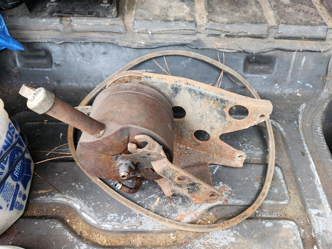
The power steering pump, bracket, and belt tucked away nicely in the Monte Carlo's trunk until I can find a spot on a shelf for this item.
For the time being I plan on pulling the electric pump from the Dodge as its currently not running. That pump is capable of pulling the necessary fuel to do the job. More on the Dodge later. Anyway, once the fuel situation is addressed, then we can attempt to crank the engine and at the same time verify we have spark, which will be indicative of the engine sputtering to life once it picks up fuel. We inch closer and closer...
Its funny how Facebook will pop up things based on your search criteria and the things you like on your timeline. This is true for a notification for a local event involving some old war planes that would be flown in for an exhibition and to offer rides at a cost. The original plan was to fly in a couple bombers, a B29 and B24, along with four other planes, a T6 trainer, a T34 trainer, a Stearman Biplane and a Beech RC45 twin engine utility plane. These planes are owned and operated by what is called the CAF, Commemorative Air Force, an organization that restores to full working condition old warplanes and flies them across the country for exhibitions as well as offering flight tours at a cost, which obviously goes towards the upkeep of the planes. 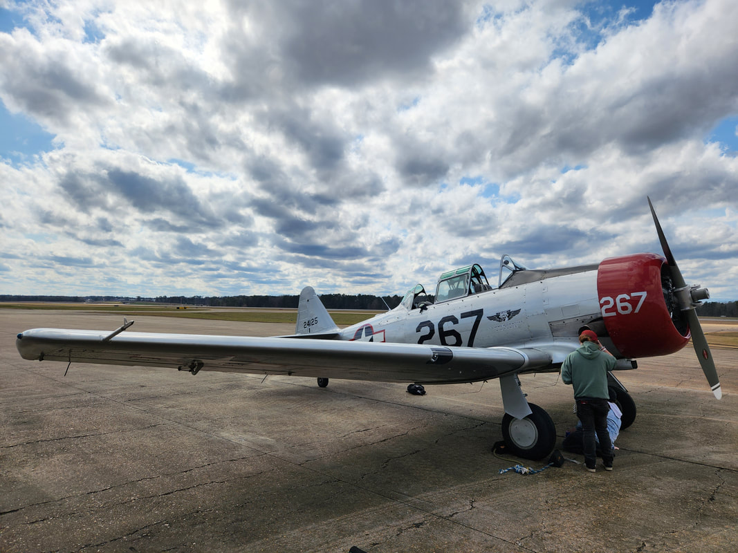 The T-6 Texan trainer aircraft 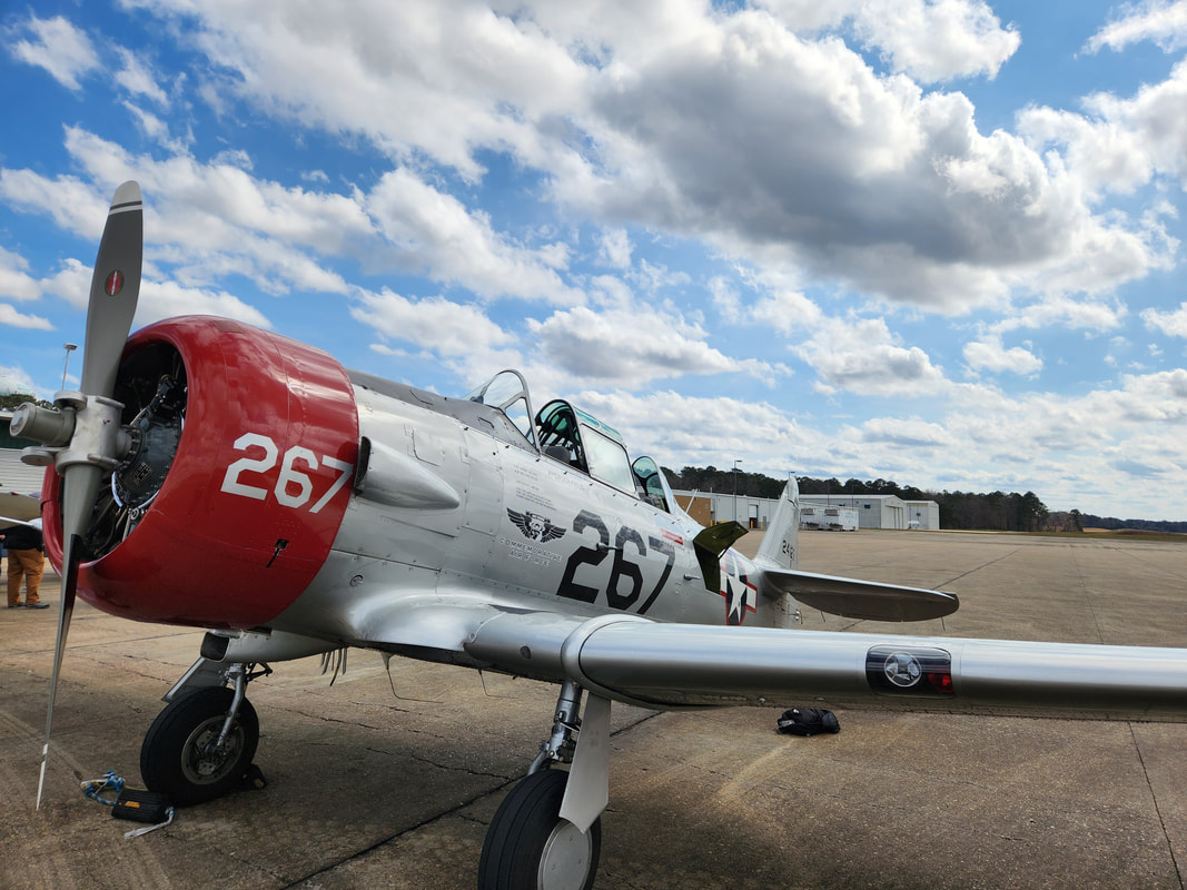 Another angle to the T-6. 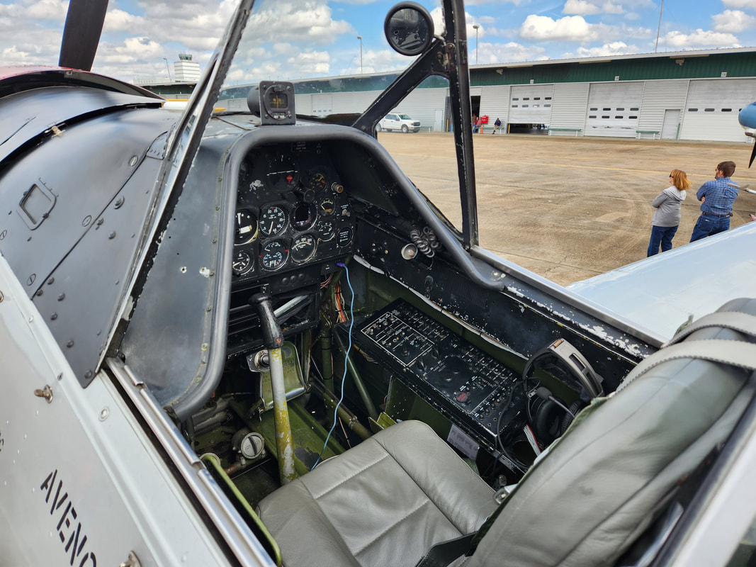 The pilot's seat, pretty simple layout when you compare it to a car, essentially the same thing with the only added gauges pertaining to aircraft, which would be easy to understand by themselves. 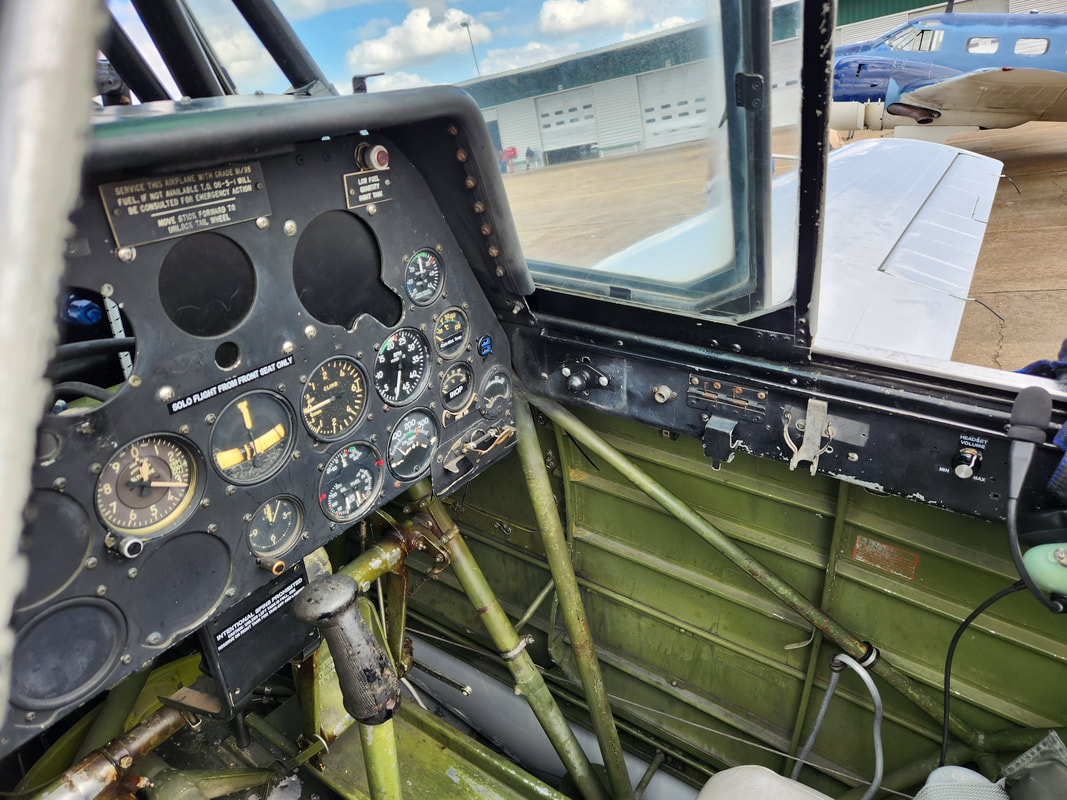 The copilot/trainee/passenger seat, with similar controls to allow the copilot to fly the craft the same way as the pilot would during training exercises. When we showed up at the airport, it was pretty windy already. Unfortunately the two bomber planes didn't make it due to mechanical issues grounding them. This is a good thing since we don't need to see any incidents with these 80+ year old planes going down because of a mechanical issue. That left the four smaller planes. This was fine as any of these planes are always cool to see, especially when they're fully operational. It's always cool to see these planes in museums but to have them fully running is like going into a time machine. 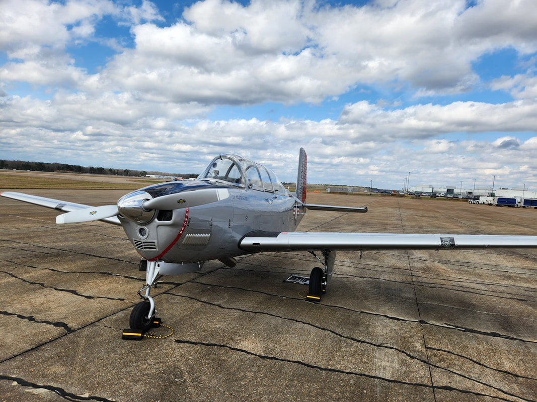 Beechcraft T34 Mentor trainer. 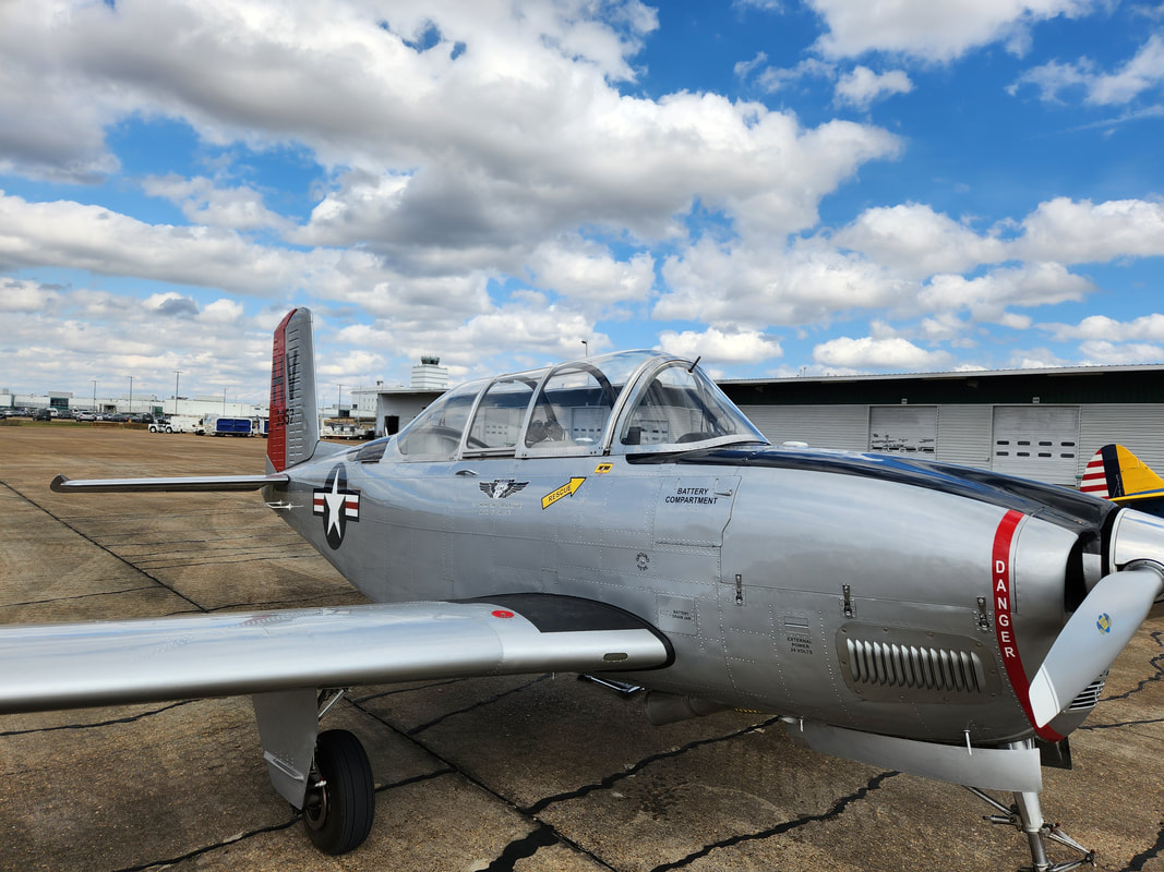 Another angle to the T34 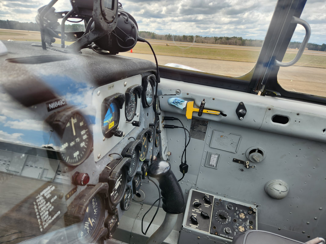 The pilot's seat, the gauges and controls are rather simple. 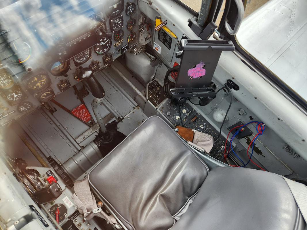 The passenger seat which would've been the trainee's seat, with the ability to fly the aircraft from this position as well during training exercises. Because of the high winds, they were not offering rides in the Stearman biplane as this was an open cockpit plane and besides the nature of the aircraft itself, rides would be rather uncomfortable in those conditions. They only offered rides in the two trainer planes and the RC45 utility plane. After reviewing the costs, we decided to go for it and take a ride. We ended up doing the RC45, as this plane is like an old school private executive plane, with seating for four, plus pilot and copilot. Since the plane was used as a trainer for bombardiers as well as utility, there were window ports on the floor where equipment once sat for bombardier training. Glass inserts in the floor allow one to look straight down to the ground below, even when up in the air. 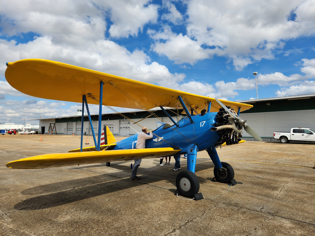 Boeing/Stearman biplane, this particular plane was built in 1944. 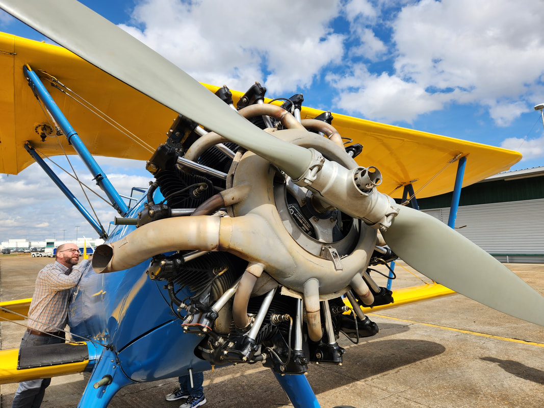 Closeup of the radial engine powering this aircraft. 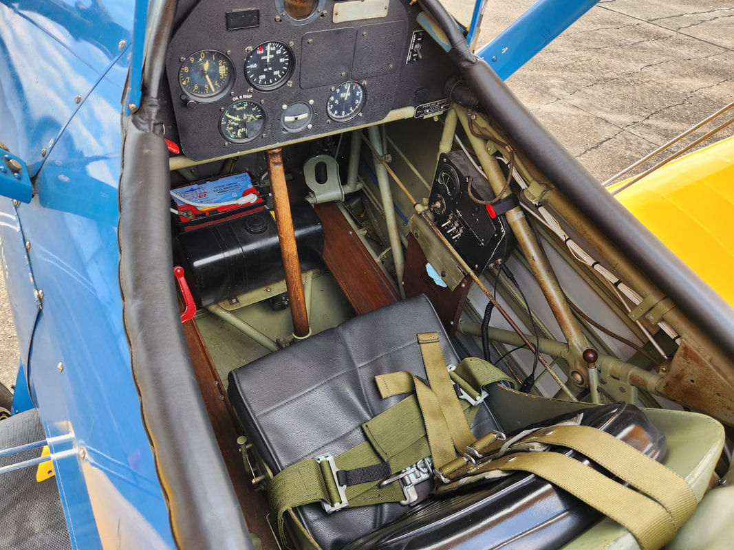 Passenger/copilot's seat. 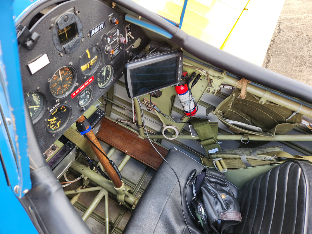 Pilot's seat, with the GPS added to help in navigating when the plane flies across the country. This plane uses a simple stick control and a couple rudder pedals. Not much different from the early WW1 versions of biplanes. 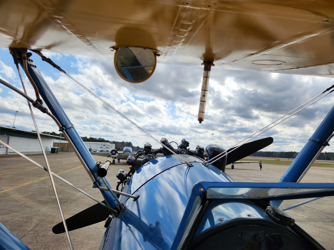 Cockpit view from the Stearman biplane. Once we were in the plane, we were shown how to fasten the seatbelts and safety harness, as was the case with the cockpit seat. Once the pilot was in, he done several pre-flight system checks and prepared the plane for startup, one engine at a time. The simplicity of the system was apparent when he had to operate a priming plunger to push fuel to the engine before hitting the switch to operate the starter, which cranked the engine off pretty fast. Once started, he took a moment to get the engine warmed up and observe the gauges as he worked the engine controls to set the RPM and fuel mixture. Once that was all done, the plane was free to start taxiing down the runway and wait for clearance for takeoff. As we started the takeoff run, picking up speed, the pilot pulled the tail off the ground first, with the plane essentially floating horizontal for a few seconds before he finally working the ailerons to pick the plane up off the ground. It's not like a commercial jet where the plane suddenly darts up to speed then seems to immediately jump up at a 45 degree angle. The plane gradually climbed, fighting the wind as it shimmied around. 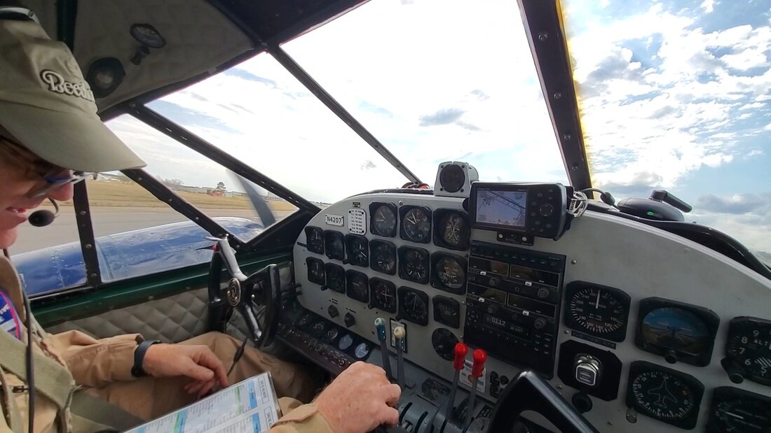 Pilot doing preflight checks before starting up the engines.  Lifting off from the runway to begin our flight. We only climbed to around 2000 ft, not really that high, all things considered, as we only flew maybe 10-15 miles out from the airport, circling around the county, out to the reservoir and around. All the areas that we normally drive through on a daily basis we were able to see from a bird's eye view, seeing how small everything looks. It's totally different compared to flying in a commercial jet, as one really doesn't get to see things from this lower altitude for long before climbing so high that the clouds typically blot out the ground below. We were able to see things from a vantage point that can only be experienced in a plane like this, or maybe from the observation deck of a skyscraper. 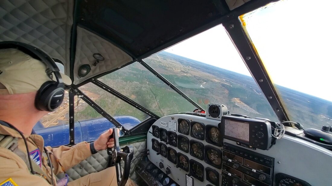 Making a soft banking to the left as we fly over the lanscape. 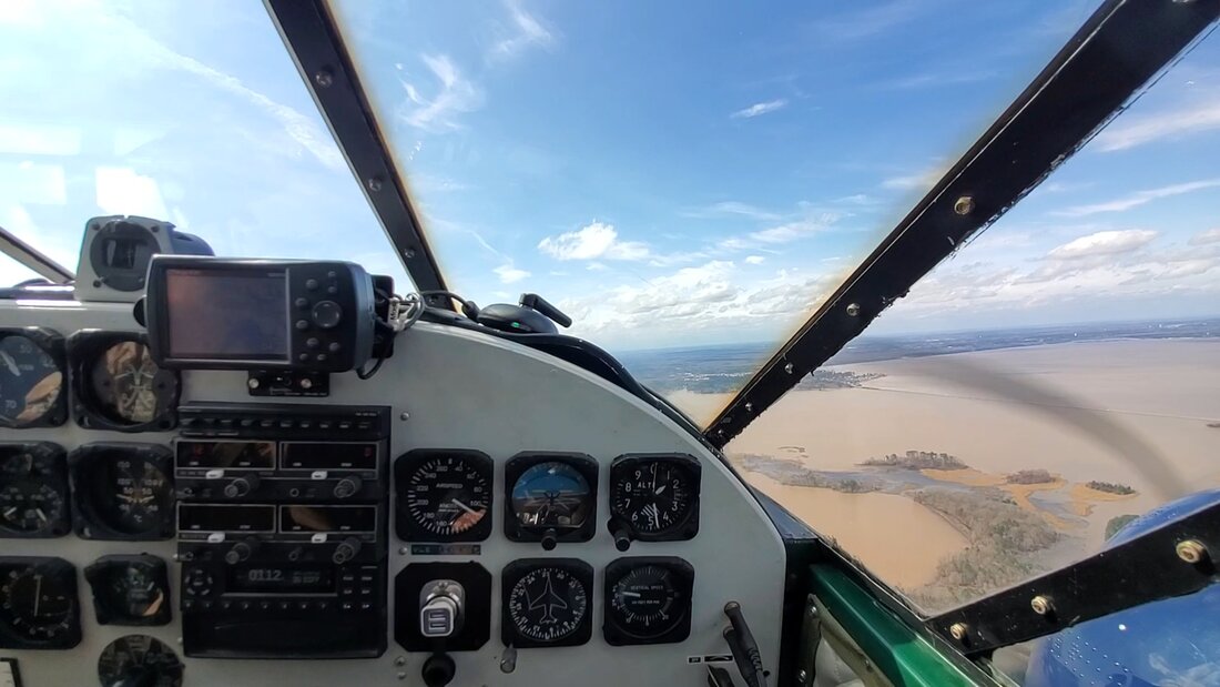 Flying over the reservoir. Of course with a plane like this, one can only imagine that the noise was pretty high. The passengers in the back got earplugs to use, while the pilot and I used noise canceling headsets. These allowed us to communicate with one another while also hearing any radio chatter coming through. The hum of the engines without hearing protection would almost vibrate your soul after a while. It's not a high pitch nor a super low rumble, but more in the middle, leaning towards the low rumble, but highly amplified, if that makes any sense. After around 30 minutes or so flying around, enjoying the chance to ride in this 80 year old plane, we made our way back to the airport, with the pilot carefully staging us and softly touching us down, taking into account the wind and its effects on the small plane. We essentially came in at a slight angle, with the plane touching down with one wheel first and the second right after, then softly letting the tail touch down. 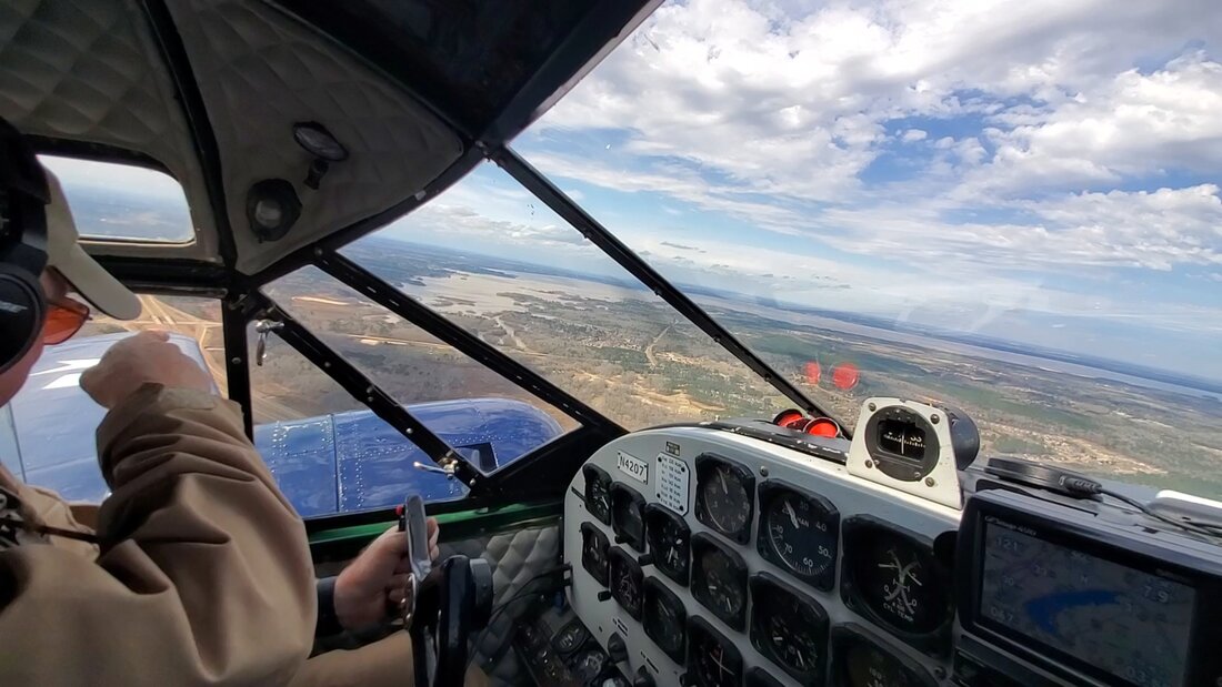 Pilot pointing at a flock of seagulls flying in formation (not visible from here) as we bank towards the reservoir.  On our final approach to the runway. Once fully on the ground, we taxied along a couple long stretches of taxi ways before finally making our way back to the spot where we were parked at, staging the plane as it was before we went for the flight. Once the wheels were choked, the pilot ran the engines dry of fuel and shut the plane down, officially ending the flight. 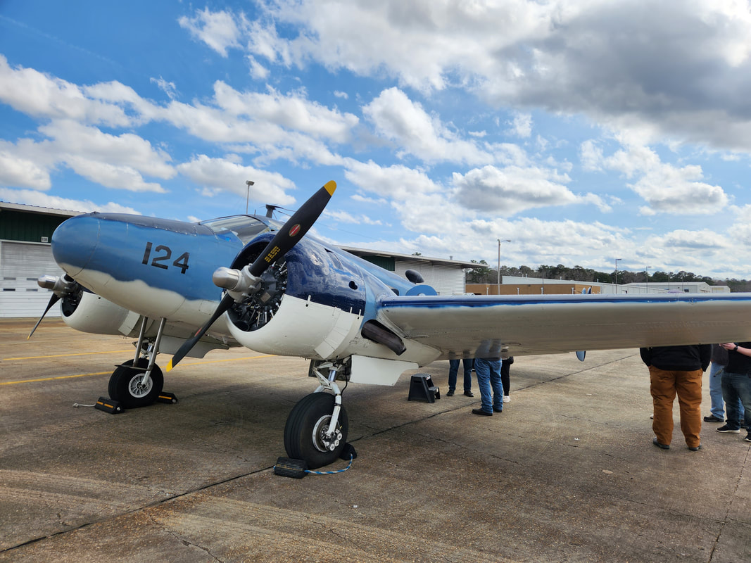 The Beech RC45J utility airplane. 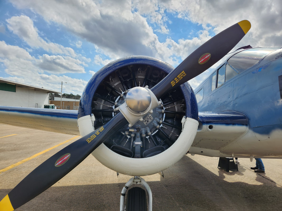 Closeup of the Pratt & Whitney radial engines that power this aircraft. This engine was rebuilt not too long ago according to the pilot. 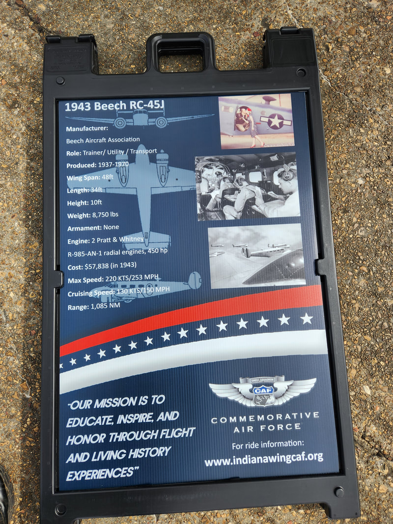 No explanation needed here. Even though we weren't at the airport that long compared to other similar excursions at museums and the like, this was still a cool experience, as we were able to witness these old planes running and flying, as well as being able to actually fly in one of them, something that most people will probably never do or contemplate doing, given some people's mistrust for something like an old airplane. But even if you don't fly in these planes, just being able to climb on them and look at the cockpits and interiors of these planes is something that one wouldn't even be able to do if they were able to see these planes inside a museum setting. With that, we were able to log in another memorable experience that will last a lifetime.
As part of a routine, I went to start up the Monte Carlo, since it hasn't been run in probably a month, give or take. There's other reasons behind this, I wanted to try and start taking steps to get this car back on the road since we're coming into a timeframe where I can drive without the worry of needing heat or AC, as this car has neither. So, when I tried to crank the thing over, I got nothing but cranking. Even with the charger in place, with plenty of juice, I got nothing. Had plenty of fuel, nothing. I threw the timing light on the thing to see if I was getting spark and again nothing. So, now it's troubleshooting time, in the ignition system, specifically at the distributor. The first thing I wanted to check was the coil to verify it was good.
The ignition coil pulled from the distributor cap prior to testing.
To check an HEI coil, I had to ohm out the primary coil and secondary with a multimeter, checking on the Battery and ground terminals for the primary and the carbon button to ground for secondary. Ohm readings should be around 0.1-1 ohm for primary and 6k-30k on secondary. The coil checked out, so the next move was to replace the ignition module, as the cap and rotor were still in decent condition. 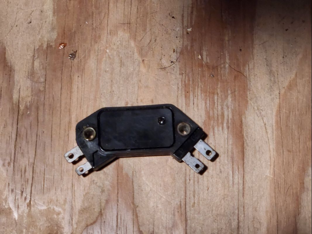
The old ignition module pulled from the Monte's distributor.
With me looking at changing the module, I figured I might as well change the cap and rotor, for shits and giggles. I had a spare HEI distributor, aftermarket of course, that I pulled these parts from, just to test out whether any of these components are bad. The aftermarket cap had an issue fitting on the stock GM distributor body but I was able to get it down, after installing the new ignition module of course. An attempt to start the car was met with failure. Apparently, this aftermarket cap was made where the tolerances were different from that of the stock hardware. It was a smidge narrower than the stock cap, so I had to go back to the stock cap, even though I did use the new rotor. 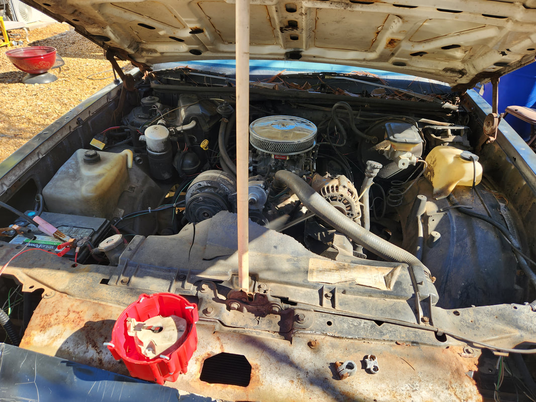
Engine currently running with the aftermarket distributor cap and old rotor sitting on the core support.
An attempt to crank was met with a couple sputters and hesitations, but still no full start. I had to start looking around. While reinstalling the timing light to check if I have spark, I noticed a power wire on the positive terminal was loose. I tightened it up. The next attempt to crank was met with a brief crank then nothing. Checking the ground cable, I found it was loose. Trying to twist it some to get a good grab on the battery post ended up with me breaking the clamp end off of the post end. Well there it is, maybe this battery terminal was the whole problem, enough to crank the starter but dropped the voltage to the distributor too low due to the bad terminal. Either way, I replaced the terminal and cranked the engine again and I guess it had to clear the flooded carb enough before it finally cranked back up. Success! 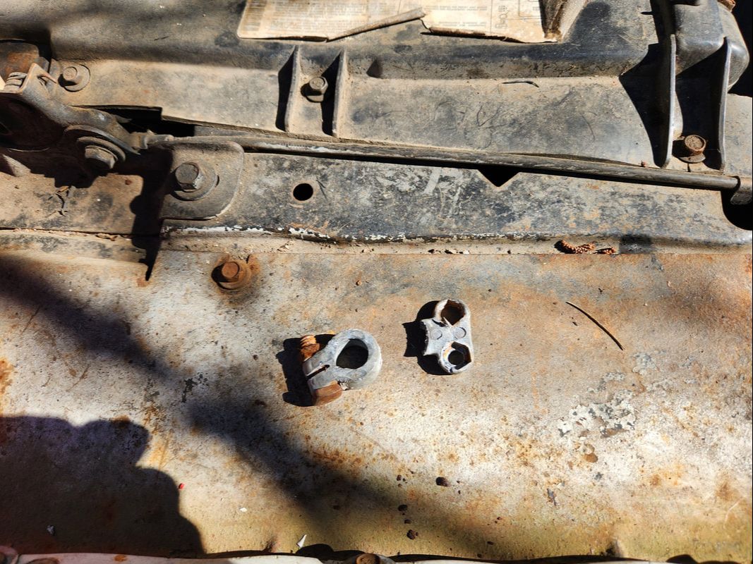
The broken battery terminal that may have been the whole cause to this fiasco.
Now with the Monte back up and running, I can move on to some other mop up work on the car. A check on the front suspension earlier found the wheel bearing was just loose. I do still need to replace the front tires as they're worn. I need to clean the interior and try to remove the moisture from the carpet. I may go ahead and replace the radio too, since it used to give me grief in the past. Other than that, the car should be ready to rock and roll.
After dialing in the rear yoke base on the driveshaft and tacking the thing in place, I pulled the unit down and took it over to a larger more powerful welder in order to do a final weld that would overshadow anything the flux core could ever do. I did have to grind down the shitty flux welds in order to finish off the areas with strong welds. Afterward I ground down all the way around the weld bead in order to ensure the bead was even and uniform so I can have a remove chance of maintaining balance. 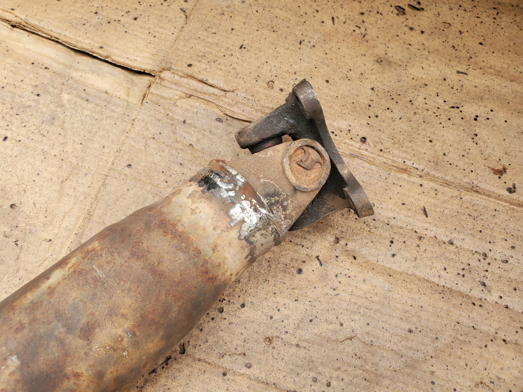 The weld on the driveshaft yoke base, ground down all the way around to ensure an even bead all the way around. With the weld all done, I reinstalled the driveshaft on the car. This is not where it ends though. I still have to balance the thing, if that's even possible on this shaft, due to the fact that it does have some dents in it (junkyard junk). The process of balancing the shaft involves jacking up the drive wheels, having someone engage the driveline then run it up to the point that vibrations are evident. The unlucky soul (me) goes under the car with a piece of chalk or something similar to mark the shaft as it wobbles, I place the chalk just close enough that as the shaft wobbles outward as far as it goes, it touches the chalk, leaving a mark, hopefully in the same spot every time it rotates. The same is done at the front and back. Next, I take hose clamps and install them on the shaft at the marks, setting the screw/clamp body at a point opposite the chalk marks to hopefully offset the imbalance. The driveline is engaged once again and as vibrations are noted, the clamps are clocked from one end to the other in an attempt to eliminate the vibrations as much as possible. It will be this point that determines whether the job was either done correctly or if it was possibly doomed from the start due to variables outside of my control. 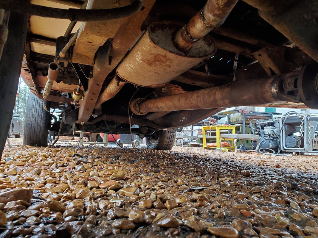 The driveshaft installed back in the Truckstang, balancing is the next stage of the driveshaft build. On a side note, I managed to do some serious land clearing along the northeast corner of the whole clearing around the shooting range area, cutting up weed trees and fallen branches along with blackberry briars and other trash. All of this detritus was stacked on several occasions and burnt. The next thing I'll have to do is come back over the area with the zero turn to grind down all the blackberry stumps and other trash that is littering the ground, as most of this smaller stuff was cut with the hedge trimmer versus cut whole and staged on the burn pile. As these areas are cleared hard, I may come back over these areas with gravel, as the intent to this area clearing was to open the area to allow vehicular traffic to move around the north fence line and into the east clearing, same as on the south fence line, which is wide open enough for anything to come through, save for the fact the ground is soft as hell. 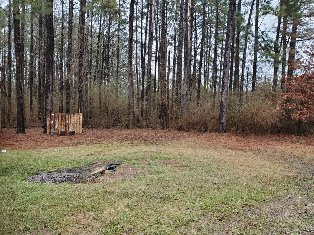 The northeast area of the east clearing, around the shooting range, cleared up to and into the tree line, of all brush and weed trees and other trash. Speaking of the soft ground along the south fence line, the gravel path is making progress towards the southeast corner. However, just like in the early days of spreading gravel in the Midway, I will have to come back over most of this area with more gravel as I drive over the gravel covered soft ground, mashing the gravel into the mud. More gravel will have to be laid until the ground can't absorb any more and I can be able to drive over the ground comfortably with the largest vehicles and rolling stock, which is obviously the point of this little path, since all rolling stock is staged in the east clearing area. 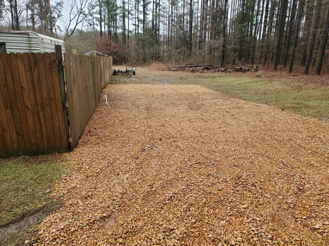 The gravel path as it leads its way further east. Note the tire tracks from past movements of the F250 as I went in further to lay gravel. This area will have to be covered more afterward until the ground can absorb no more gravel. Little by little I get closer to getting Truckstang complete, its technically able to be started now, just need fuel. I still need to add an oil pressure sensor and gauge set so I can at least know that vital status of the engine while trying to run and tune the thing. Once I do get the engine running and dialed in, I can move on to checking the driveshaft to see if my work was good or if I'd have to go back to the drawing board. As for the landscaping, I cleared enough area that I'm happy, just gotta wait for the ground to harden so I can safely run the zero turn over the ground to grind up everything. As for the gravel spreading, well, I'll be doing that for the foreseeable future...
As part of a new plan to wrest a little more control over the costs that can be involved with building a car, especially something of this nature, I decided to take a stab at shortening the driveshaft I picked up for Truckstang from the junkyard. Prepping the shaft is the easy part, but this is where the simplicity ends. Once the yoke is separated and the tube shortened, the next phase is to reassemble the yoke to the tube then check the runout on the driveshaft using a dial indicator tool. This tool has a plunger that rests against the tube on the driveshaft and as you rotate the driveshaft, the amount of wobble is translated to a reading on the scale of the indicator. If the yoke isn't true in the shaft tube, the runout or wobble will be excessive and show on the indicator and would even be visible to the naked eye.
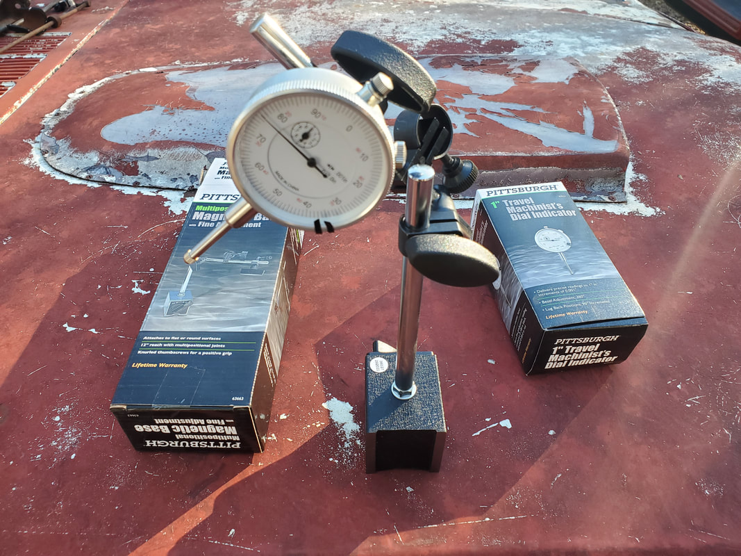
The dial indicator and magnetic base, two separate tools that make up the set that is required for performing the runout measurements on a driveshaft.
Part of the dial indicator set is the magnetic mount that holds the actual gauge. This mount hangs or rests at some point under the car and has a couple arms that can be adjusted to place the indicator gauge at the desired point on the driveshaft (or other rotational device) so it will be stationary as the driveshaft is rotated. 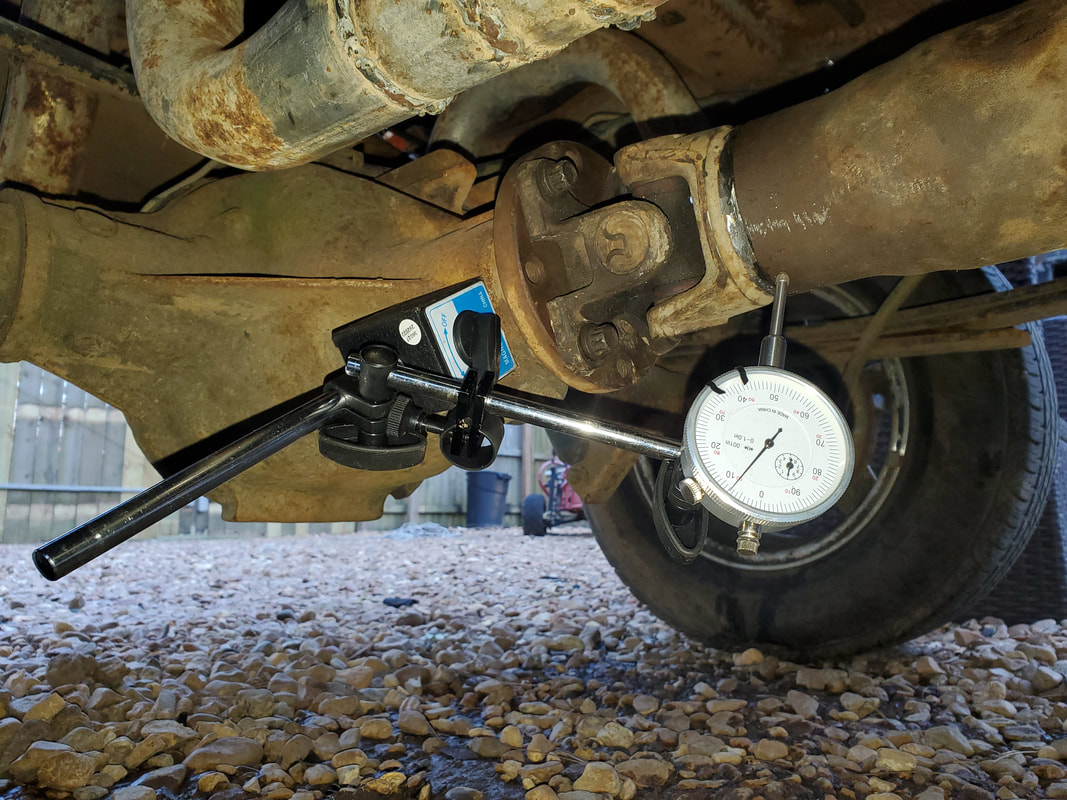
The dial indicator and magnetic base in place on the rear end and against the driveshaft tube, prior to performing our measurements.
With the gauge situated in a spot that was satisfactory, which had the magnetic mount stuck on the front part of the differential body, the gauge was in position. When in the standby position, it doesn't read zero, but will require a light pressure on the plunger to get to the zero point. This way, the variations can be read below and above the zero point. If the gauge bottomed out at zero, if the shaft rotated away from the gauge, it would end up losing contact for a brief moment, giving an inaccurate reading. So with that bit of info, the gauge had to be pressed against the surface of the driveshaft tube to get as close to zero as possible. It doesn't have to be exactly at zero as simple math can help one figure out the variations in gauge needle movement to give the readings needed. At this point, I jacked up the right tire and put the transmission in neutral to rotate the tire and hence, the driveshaft. As I rotated the shaft, when the shaft rotated to the point where it had maximum pressure against the indicator plunger, I tapped the yoke lightly to try and "work" it a little, watching the gauge change. I then rotated the shaft again, checking the variation and repeating the same thing until the variations were small enough to put the reading within tolerance. Researching different sites had the runout at anywhere from 0.010" to 0.020". I had a runout variation of around 0.012", which was a middle ground compared to what others have stated. With that, I pulled out the welder and added four shitty tacks equidistant from one another around the shaft and yoke to hold things stationary. I checked the runout once again to confirm that nothing changed. Once I confirmed this, I pulled the shaft so I can do a finish weld with a more powerful welder. The little flux core is not the kind of welder that needs to be used for making this kind of weld as this thing needs to have a super clean and solid weld that can't be delivered with the flux core machine. Even after I weld the yoke in place I'll have to grind the weld slag to even everything out as any excess slag in any one spot can throw the shaft off balance more than it may already be. 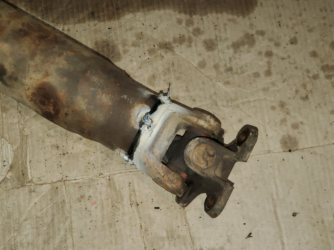
The rear yoke base of the driveshaft with the wack tacks in place to hold the base in place prior to the final welding.
Once the welding is done on the shaft and the slag ground down and the shaft reinstalled, there's a matter of balancing. Now, this can go a couple ways. The common denominator here is that old heads would use hose clamps as the weights for setting the balance. Now, the more in depth method is jacking up the rear end and safely mounting the car so it can be put in gear and accelerated to highway speed or something close to it, or otherwise to the point that vibrations are noticed. One then takes a piece of chalk and holds it just close enough as the shaft wobbles to allow the shaft to knick the chalk. These marks are the points where the shaft is wobbling to the maximum point in that direction. This is done at the front and back of the shaft. The hose clamps are placed 180 degrees opposite from the chalk marks then rotated slightly as the driveline is run up to speed, doing this stop and go method several times until the driveline can be run with a minimum of vibration. Only then can the shaft be considered balanced. If this cannot be achieved then its likely something else is off. Maybe the U-joints are out of phase or the tube is bent. Either way, it would mean starting over from scratch. Hopefully we have everything true. I did read of other bootleg methods shadetrees used. One of my favorites is where one would drill a hole in the shaft, and inject oil into the shaft then plug the shaft. The oil provides a form of internal fluid balancing that may very well have to be utilized if our efforts at balancing fail.
|
