|
After taking initial measurements and cutting the driveshaft tube in order to get the length I needed, I verified the alignment to the best of my eye and tapped in the U-joint/yoke base with the U-joint end lining up with the other end on the front base. Once that was all done, it was a matter of remounting the driveshaft in the car as it would be in its final state. 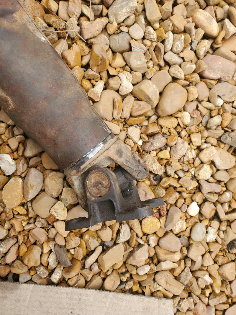 The yoke base tapped back into the end of the shaft tube after trimming the tube down. The point of remounting the driveshaft is so I can install/set up a dial indicator tool on the end of the driveshaft tube. Once this is done I'll have to jack up the rear end so I can rotate the driveshaft, which in turn will turn the wheels. With the driveshaft free spinning, the dial indicator will be able to show me the amount of runout, allowing me to tap on the U-joint end in order to try to get the runout as low as possible. Once this is done I can tack weld the base to the tube in a few spots, then check the same runout number again to verify its still true. Afterward I can pull the driveshaft and fully weld the unit with a high powered welder in order to ensure a good even weld all around. Once that's done, I will then be able to attempt road tests when the car is made operable in order to see if I need to attempt a balancing act with a worm clamp, an old school shade tree method of balancing a driveshaft by attaching a worm clamp in place and rotating it, with the mass of the screw tensioner serving as the weight for balancing. More on that when the time comes. 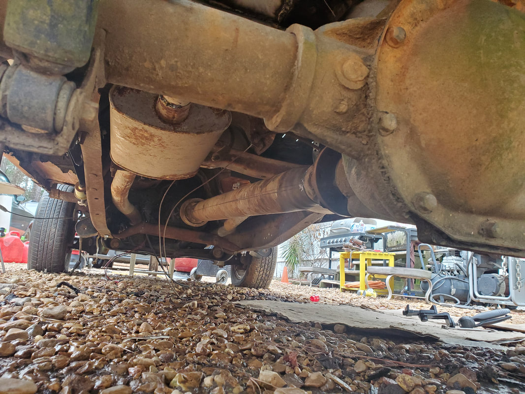 Driveshaft installed back under car pending installation of dial indicator gauge to find the shaft runout in order to tap the yoke base to make it true. On a lighter note, I did conclude the day with some more landscaping, with the idea of continuing to clear out a large area around where the shooting range is at, trying to clear the grounds up to the tree line. As I've done in the year past, I want to try and maintain this cleared tree line so we can have free use of the yard grounds outside the fenced in compound for various uses. Allowing brush to grow back will prevent me from being able to maintain the grounds with the zero turn mower so I need to stay on top of this, even for aesthetics. 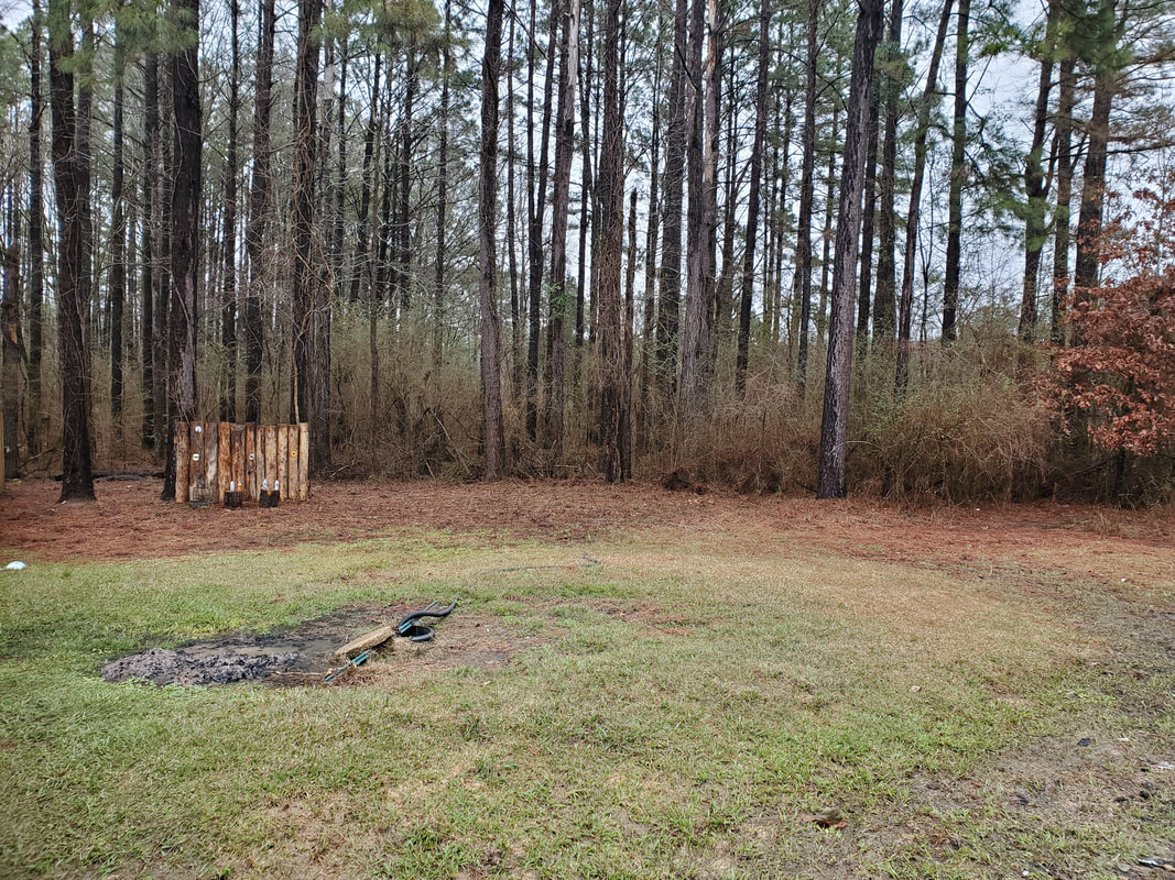 The greater yard area cleared after several consecutive episodes of brush cutting and burning. I will be getting a dial indicator next so I can get the party started on the driveshaft. Once the shaft's done, nothing is stopping me from getting Truckstang running and ultimately driving. Everything is in place, other than adding some fuel. I will still need to add an oil pressure sensor and voltmeter to be able to read those vitals, even though I already have the USB voltmeter in the 12v receptacle. These gauges would fill the slots on the gauge panel I mounted a little while back. These gauges aren't stopping me from running the car, but oil pressure is an important vital I need to be able to read if I'm to run the engine for long.
0 Comments
One of the things that is slowing me down from really just finishing Truckstang and getting into testing is the fact I need a driveshaft for the car. Now, it's nothing to take the driveshaft to the driveline shop and have them shorten it, as I've done many times before with other driveshafts. Problem is, it's a little pricey and at this moment, finances aren't really allowing us to just drop the money needed to get a driveshaft shortened. What's the other option? Well, shorten it myself of course. However, there's more to this job than just cutting and welding the yoke/U-joint end back in place. Proper balance needs to be maintained or taken into account. There's a couple ways this is done. 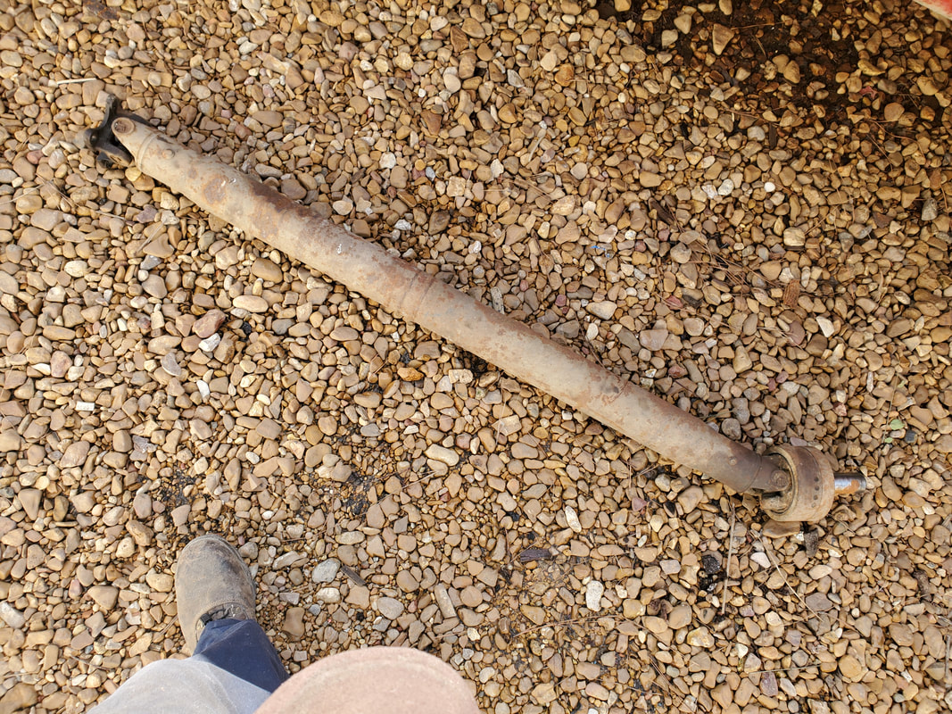 The Ranger driveshaft, sourced from a short bed/cab truck at the junkyard. The first thing that needs to be taken into account is maintaining the alignment of both U-joint bases. If you look at any driveshaft, both U-joint bases will be at the exact same spots, front to back. When cutting off one of the bases, that proper alignment must be noted to achieve proper reassembly so both bases are in line with one another. 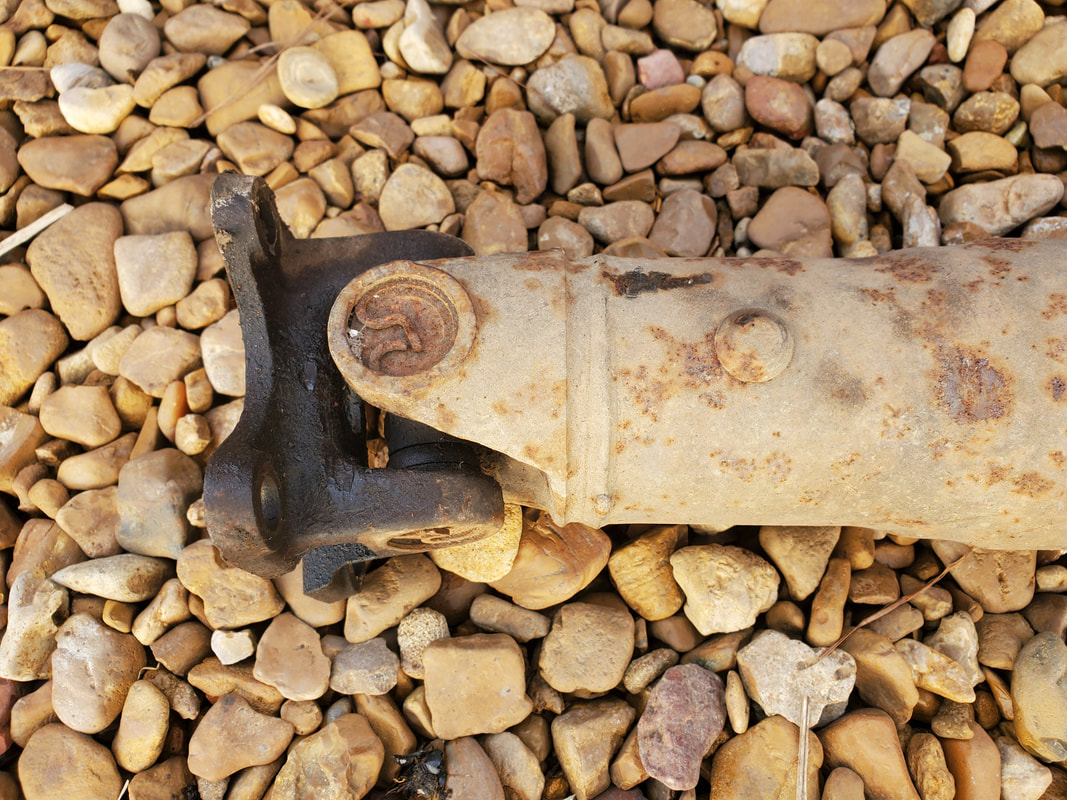 The rear U-joint base and rear end yoke. The weld will be ground out, then the base tapped out to remove the base. It's easier and safer to do the shortening work at the rear versus the front. 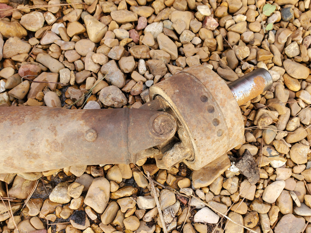 The front U-joint base and yoke, this will not be cut. All work will be done on the rear. For safety reasons it's better for any failures to occur on the rear of the driveshaft. A driveshaft break at the rear will just result in a shaft flopping around. A break at the front will cause the front to nose down, possibly wiping out the car. With that one thing noted, I will have to grind out the weld that holds the base to the driveshaft tube. This is relatively simple, carefully grinding out the weld slag until I'm able to hammer out the base. Welding the base back in has to be done evenly as well, too much slag in any one spot will throw the shaft off balance just as well. I will have to do my best to maintain an even weld and even then, be ready to grind excess slag off.  The rear U-joint base cut free from the driveshaft. The next thing is measuring to see how much of the driveshaft tube to cut off. The easiest way I figured out to do this was to mount the rear base to the rear end base, then insert the yoke into the transmission tail. Afterward, I'd line the rear of the cut end with the rear U-joint base, marking the spot on the driveshaft with a marker. I don't have to have a perfect circle drawn on the tube, just marked. Reason being, when I cut the tube, I have to try to maintain as straight a cut as possible with no real angle. Otherwise, the U-joint base will go in crooked and will never be in line with the rest of the shaft. 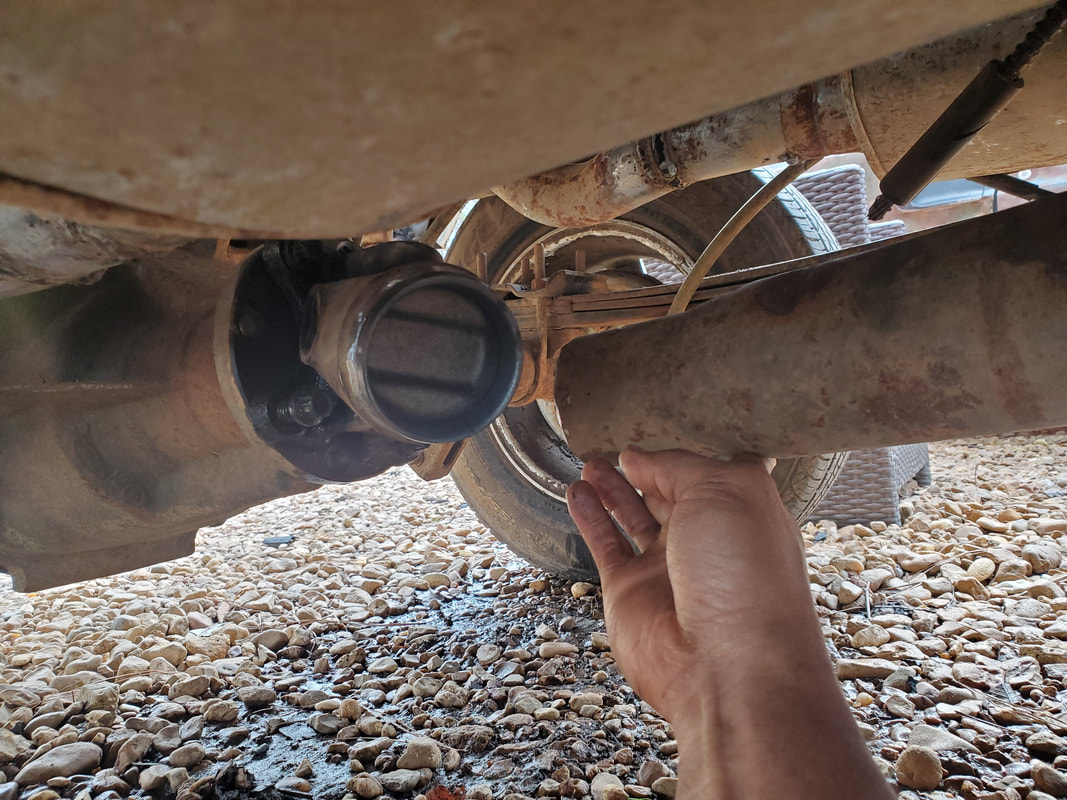 Lining up the cut end of the driveshaft tube with the rear U-joint base to get the point that I'll need to mark for cutting the excess tube. I'll use a belt saw to cut the tube, using a base to hold the shaft, and a level to make sure both the saw body and the driveshaft tube is level. I'll adjust the pedestal base to achieve this leveling. Once the tube is cut shorter, I'll tap in the rear U-joint base, taking into account the alignment of both front and rear bases. I will need to source a dial indicator with a base so I can do a measurement called shaft runout. This measures how much "wobble" the shaft has as its rotating. The amount of movement is probably not enough to be seen with the naked eye, but the indicator will see it. The indicator is mounted to a stationary point under the car and the measurement shaft is placed against the surface of the driveshaft. A wheel on the end allows the shaft to just rotate against the wheel without moving the indicator gauge. When the rear U-joint base is tapped back in the driveshaft tube, it won't be welded in, in order to make adjustments for runout. As I rotate the driveshaft and note the runout measurements, I can tap the base accordingly to straighten out the piece in the tube, until rotation gives me a runout number within tolerance. Once that's done, I can tack weld the base, take the measurements again to verify the runout is still in tolerance, then remove the piece for final welding. Afterward I can then test the car, noting any potential vibration that may call for some weight to be added. That will be another procedure discussed when we get to that step in the project.
When one comes so close to the end of a large project such as this one, it becomes more known all the small odds and ends that need to be addressed to wrap up things. After installing things like engines, fuel tanks, whole interiors and the like, there's all the small things like small hoses, fittings for hoses, brackets for gauges, wiring to different components, even the final routing of wires once everything has been fully established. In our case at this moment, once the carburetor was installed and hooked up, there were a couple things I still needed to address in that circuit. I still needed to install the PCV valve and hose that would connect to the carburetor, and while I was at it, a length of hose between the vacuum hose manifold and brake booster. These couple little hoses would further complete the fuel/air system. Other than a stud for the air cleaner, the fuel/air system is complete.
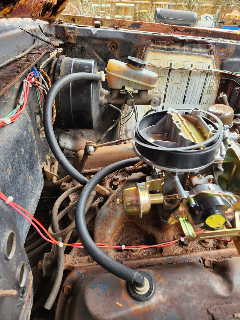
PCV valve in place with hose along with hose for brake booster connected to vacuum hose manifold at rear of intake.
Another thing that I had to address was the mounting of the fuel gauge. I needed to get a bracket that holds these universal gauges and drill a couple holes to secure the bracket in place. On a little trip to the junkyard to search for parts for another vehicle, I managed to stumble upon a triple gauge bracket that had a temp gauge still installed. Unfortunately that gauge was defunct but the bracket was more than usable. While I only have the one gauge in place, I still need to add an oil pressure gauge, and since I have another spot open, I chose to install a volt meter to complete the triple gauge bracket, since the only working voltmeter in place is a little USB charger that plugs in the cigarette lighter socket and reads the voltage at the socket. Rather than use this method of reading the system voltage, I'll just add a dedicated voltmeter. 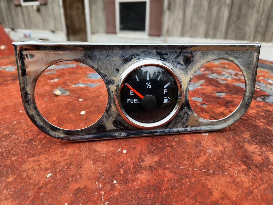
Fuel gauge mounted in the middle hole on the bracket.
After drilling the holes under the dash at a central point over the old transmission hump, I mounted the bracket, with the fuel gauge mounted in the center hole, in place. With the gauge plugged back up, even before I add the other gauges, I can at least see this gauge's installation as complete. Another thing that I managed to get my hands on while at the junkyard was a battery. 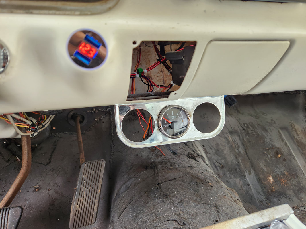
Gauge bracket mounted in place with the fuel gauge mounted in place under the dash.
When I welded up the battery tray, I made the mistake of not sizing up the typical battery that I would use to determine if I would need to add some extra metal to make the battery tray. Even though I didn't have any extra metal on site, it would've been nice to have the battery tray set up to be able to accommodate a series 24 battery, which is typical of what I use in most of the vehicles around here. Because of this little mistake, in order to hook up a 24 battery, I had to rest the thing on the edge of the battery tray, hardly a permanent setup. I determined that I would have to use the GM style side post battery, which surprisingly was optimized for this battery tray set up. The positive terminal would be well away from the side panel and still in range of the cables. So, while at the junkyard, I grabbed a side post battery (don't know what class number it is since we don't typically use them). I installed this battery, confirming that this class battery was perfect for this setup. 
The side post battery resting nicely on the battery tray wiht the cables connected. Note how the positive terminal is safely away from the side wall.
With the battery fully installed and ready to go, we can technically write off the electrical system just as well, since we're not doing this temporary bootleg setup with whatever battery we had available. Other than the couple gauges previously mentioned, and the heater box, the only big thing left is the driveshaft. The driveshaft is a spectre that I want to get started on and completed but have many reservations about doing due to the fact that there are things that have to be taken into account all the way through the process of cutting the old shaft and getting to where I'm doing final welds on the "remade" shaft. Its very important to heed to every step in this process, otherwise the driveshaft will end up vibrating itself to death, taking the transmission and possible the rear end and undercarriage of the car with it. Now, if I had a few hundred bucks disposable money I could just bite the bullet and have the shop do it and get it out the way...
One of the things that I had to do on Truckstang to remedy a minor issue with the fuel system was repositioning the sending unit so the float would be in the opposite position when the tank is empty. It was a simple matter by just clocking the unit so the angle of the unit would have the arm swing to the other end of the unit when in the empty position. I would also have to bend the wire holding the float since the new position of the sending unit would have the float hit the side of the tank. This simple matter of bending the wire rod a little at a time and test fitting the unit until the float was in the right position to have free movement when mounted. I'll have to fill the tank to fully test the thing but the arm on the sending unit did sit on the opposite end of its swing when mounted. Things should work based on how the unit moved. I applied some gasket maker to the rubber gasket since I was only able to screw down two out of the five screws on the base. Hopefully this thing will seal good otherwise I'll have to drill some extra holes or widen the existing holes to get the thing to fully mount down where it will seal.

The sending unit from the LUV fuel tank, with the float rod twisted to allow for free movement after clocking the unit around to allow the lever to fall to the opposite side when the tank is in the empty position.
On a lighter note, I had a little task I had to tend to on the F250. The truck was beginning to act funny at times, with the idle dropping down to the point of stalling unless I hit the accelerator some. I attempted to remedy the problem by swapping out the idle air solenoid (IAS), which didn't solve the problem. I ended up tweaking the throttle idle screw to give the engine a little higher idle than normal. This sorta worked but the engine would still have some episodes of erratic behavior, where sometimes the throttle response was not quite right. Sometimes the truck would be fine, sometimes it would take some finessing of the throttle to get the engine to ramp up, especially under load. This lead me to believe the throttle position center (TPS) was faulty. I ordered a replacement unit online and had been putting off the replacement of the unit, due to the fact I would have to pull the throttle body. 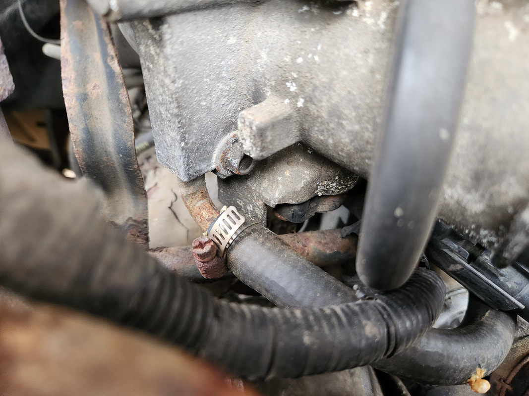
The TPS is located at the bottom of the throttle body, dead center in the picture. The throttle body would have to be removed to replace this piece.
There are four bolts holding the throttle body in place. First the air intake tubes come off, then the two throttle linkages are removed. Only two devices are plugged up, the TPS and IAS. A couple coolant hoses are hooked up that circulate coolant through the throttle body to preheat the incoming air. After those two hoses come off, one vacuum hose is left to remove. With that, the throttle body was off. Surprisngly, the gasket didn't split so I wouldn't have to replace it. I would still apply gasket maker when I reassembled everything for safe measure. 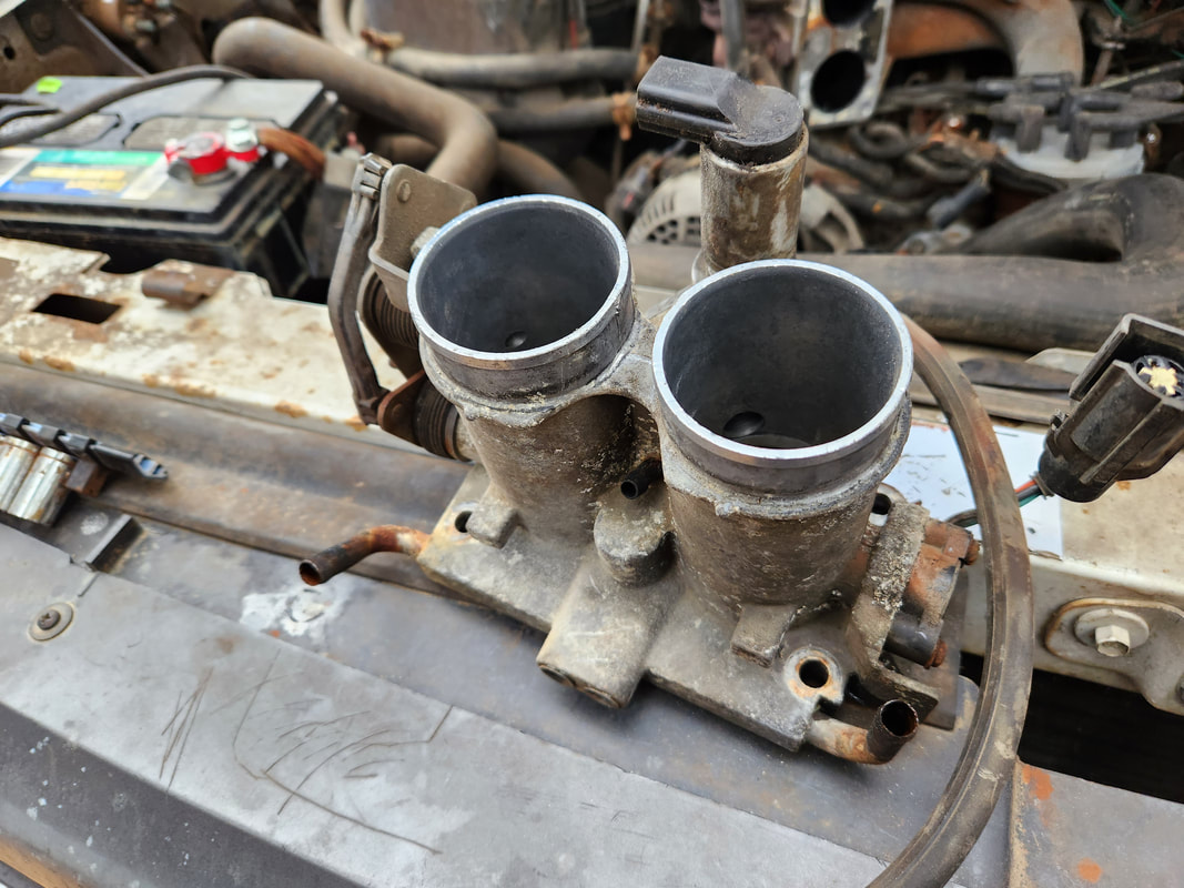
The throttle body removed from the upper intake plenum. This thing was nasty and will warrant a cleanout at some point in the future, along with a new gasket.
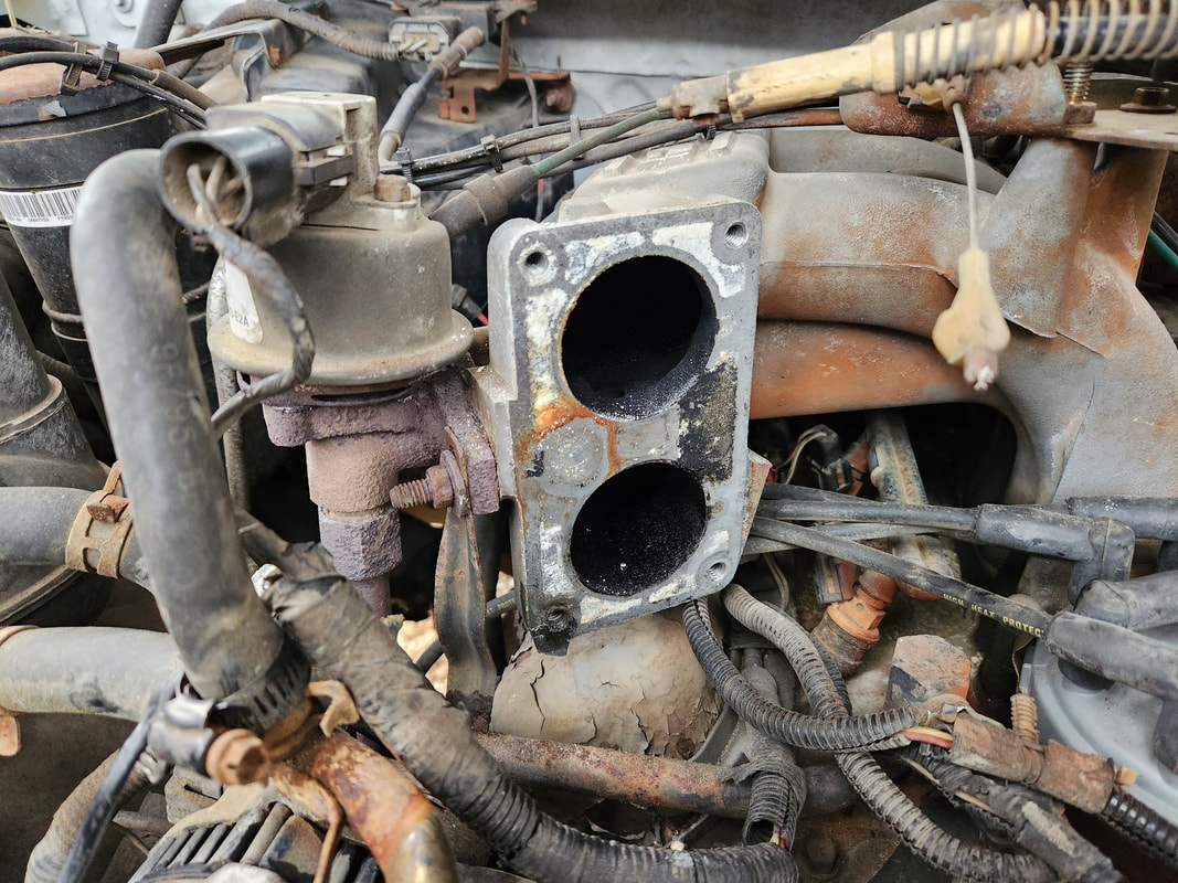
The surface of the upper intake plenum after removing the throttle body. The surface will be scraped clean and gasket maker applied before reassembly.
Two screws hold the TPS in place. These screws appeared to have been in with thread locker, so this TPS was probably never replaced. After pulling the screws, the old TPS was out. I wet the screws down so they would go back in without fanfare. The new TPS was lined up with the shaft of the throttle plate and bolted back down. Gasket maker was applied and the throttle body bolted back down. 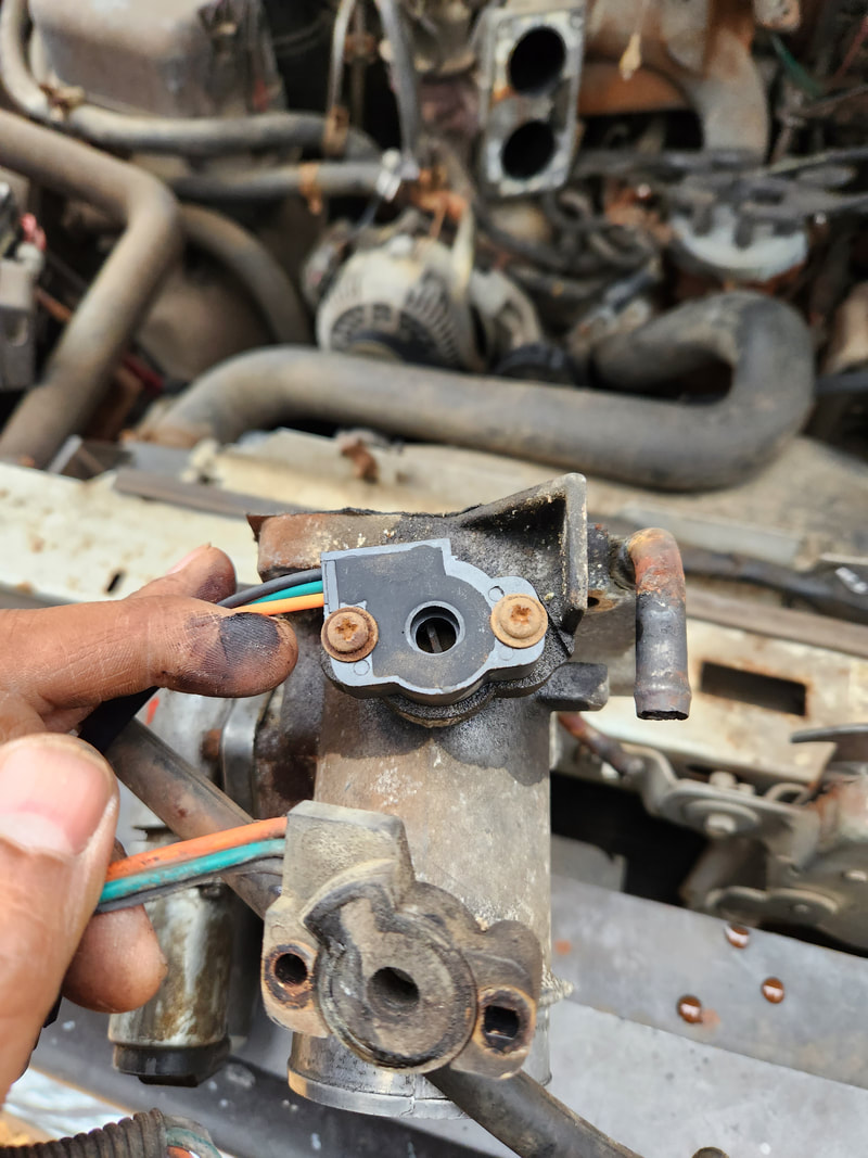
The new TPS is in place on the throttle body, with the old TPS underneath for comparison.
Surprisngly, after reassembling the throttle body and everything associated with it, the truck started up quick and easy like it was brand new. At first the throttle response was a little spotty, not ramping up seamlessly from idle to WOT but it wasn't bad. I adjusted the idle screw to get it back to where it was originally. As the engine warmed back up, the throttle response got better and better. Even in gear the throttle response was good and became smoother. I let the truck run a while just to see if it would do any of the sporadic behavior it did before. The truck continued to idle like normal with no issues. I was satisfied that things might be fine, so I shut the truck down, happy to have this one issue resolved. I still have to troubleshoot the braking system to see where I'm losing brake oil. From the way the truck acts when the oil gets low, I'm believing a rear wheel cylinder may be bad. I also need to check the front suspension to see how the ball joints are, along with the tie rod ends. It's about time I get things straight with this truck so if I need to make a long haul, I can do it confidently, knowing the truck will make it back home in one piece.
|
