|
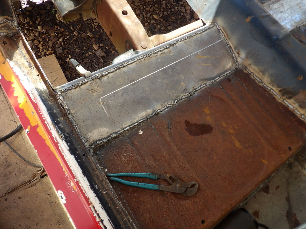
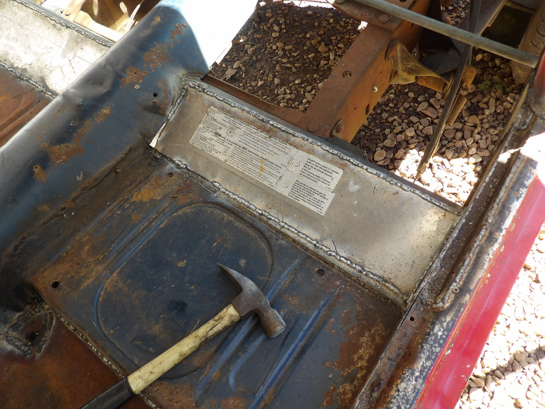
With the body panel secured in place slightly with a few tack welds, I had to verify the fitment of a couple of brackets that go on the inside where the taillight panels are connected to the panel. This bracket also holds a mounting point for the two rear interior panels that cover the corners of the rear of the body. After a little manipulating of the taillight panel sections of the body, I managed to get the brackets to bolt in place where they needed to be. From here I focused on getting the taillight panels situated where things would be lined up as best as possible. Everything needs to be working together so the taillights, bumper pieces and hatch all fit together as best as possible. 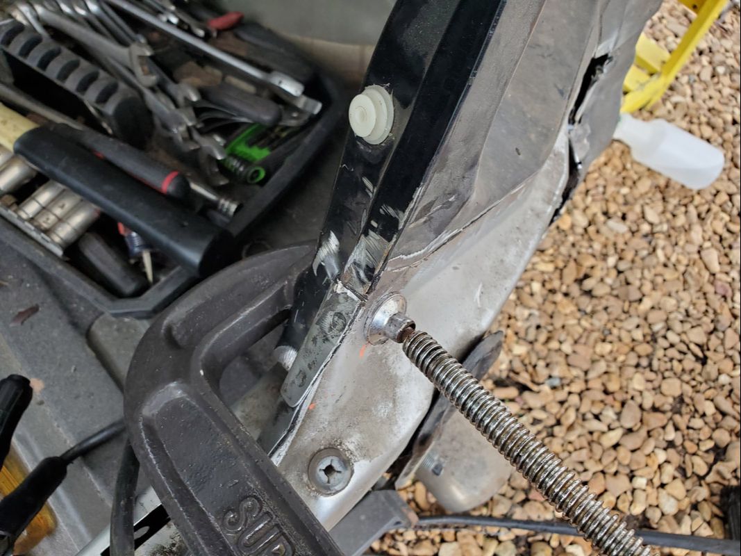 Right taillight panel stretched in place and held with a C clamp to hold its position prior to welding. 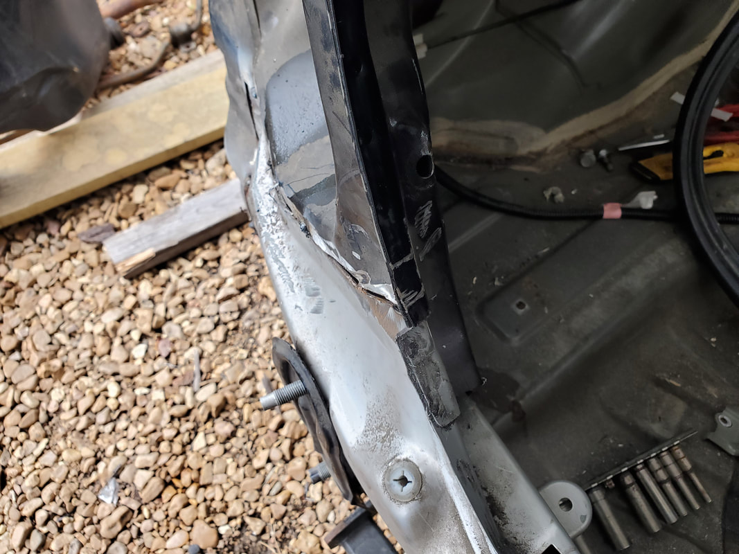 Left side taillight panel didn't need much manipulation to get it to line up with the body panel. 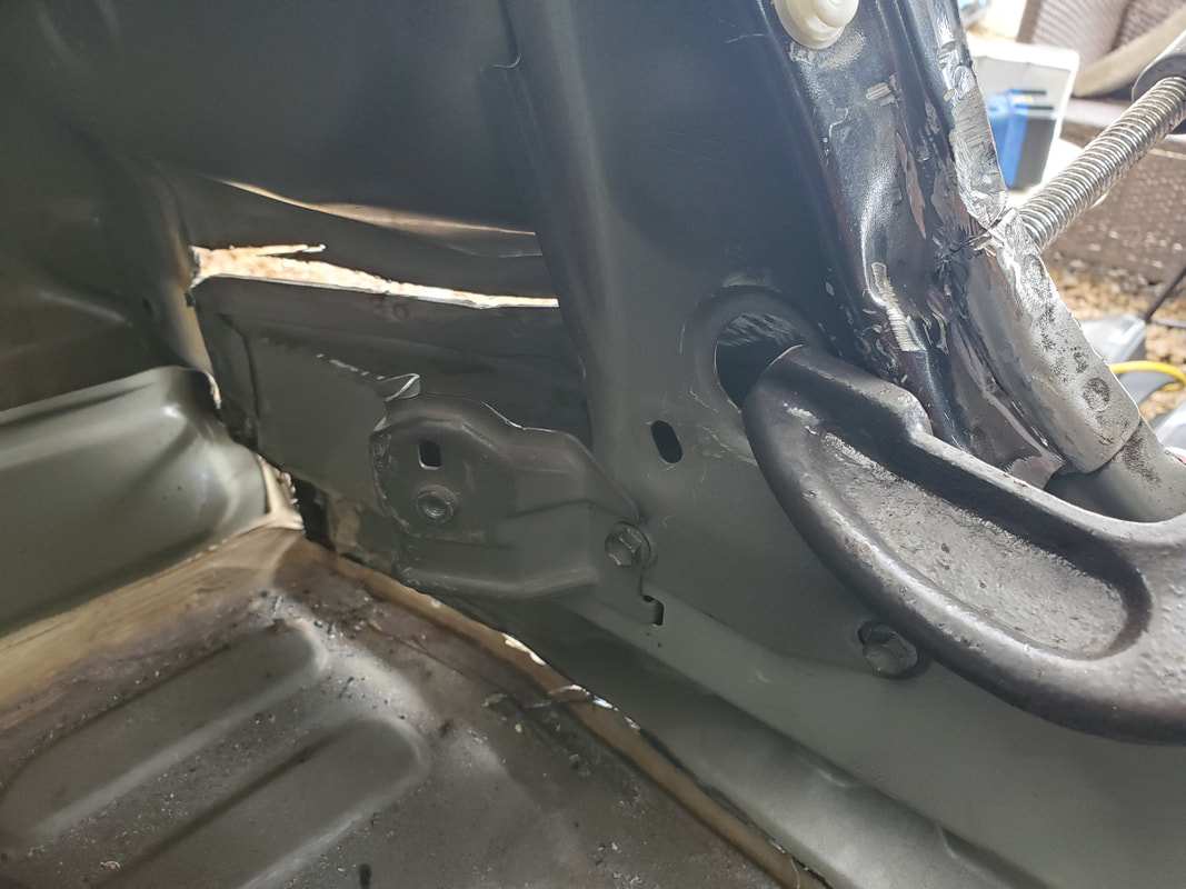 Right side bracket that holds taillight panel to lower body panel. 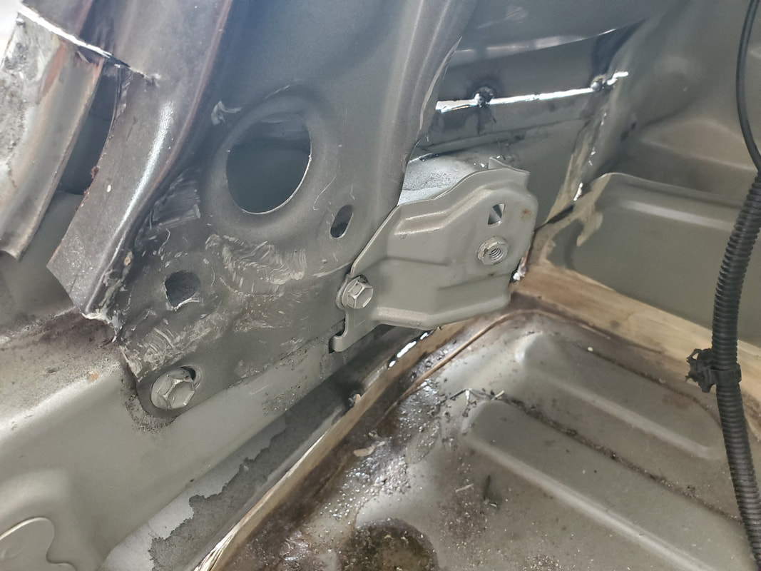 Bracket in place on left side holding taillight panel bottom in place. With the taillight panels in place where I wanted, I applied some weld to those joints to get to the point where I could actually do a temporary assembly of all the bumper parts to see how things line up. I wanted to do this before I do the final welding so I can at least be sure things line up all around since the last thing I would've wanted to do is cut through fresh welds just to realign the panels. 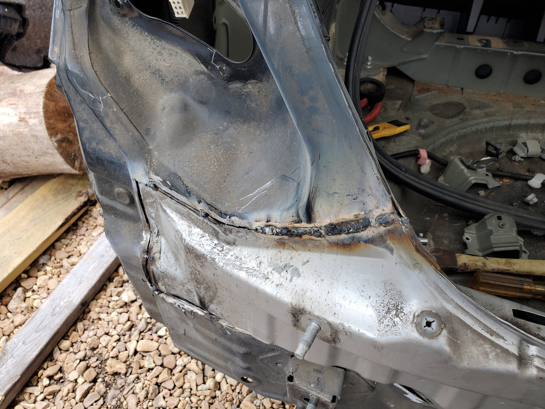 Weld seam applied to left taillight panel joint to hold it in place. 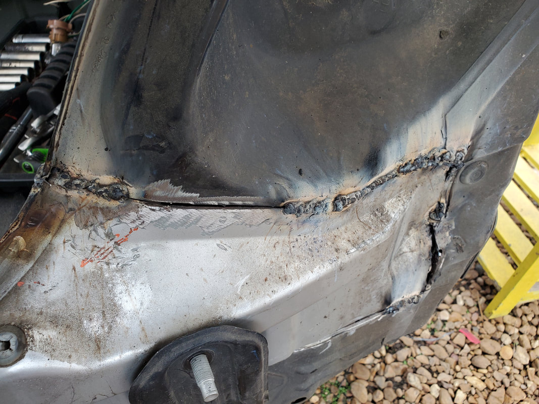 Right side weld seams on taillight panel. At this point I put the taillights in place then put the inner bumper bar in place. I only used two nuts to hold the bumper bar in order to keep it from shifting around. I applied the foam pad then the bumper skin and from there closed the hatch. Everything looked pretty good so far, even though I should've fully bolted down the taillights to ensure the units fit flush against the body as later I'd find there was a minor mis-fitment once everything was secured. With everything looking good I pulled the bumpers and taillights apart and started welding everything together, having to apply some extra metal in spots where the seams had more gaps than I could work with in the welding. 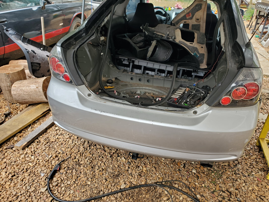 Taillights, bumper bar and skin all fitted in place to test the alignment of all the panels. 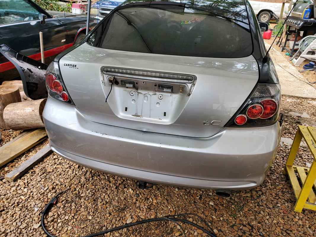 The hatch closes pretty good on the rear, not really leaving any noticeable gaps. 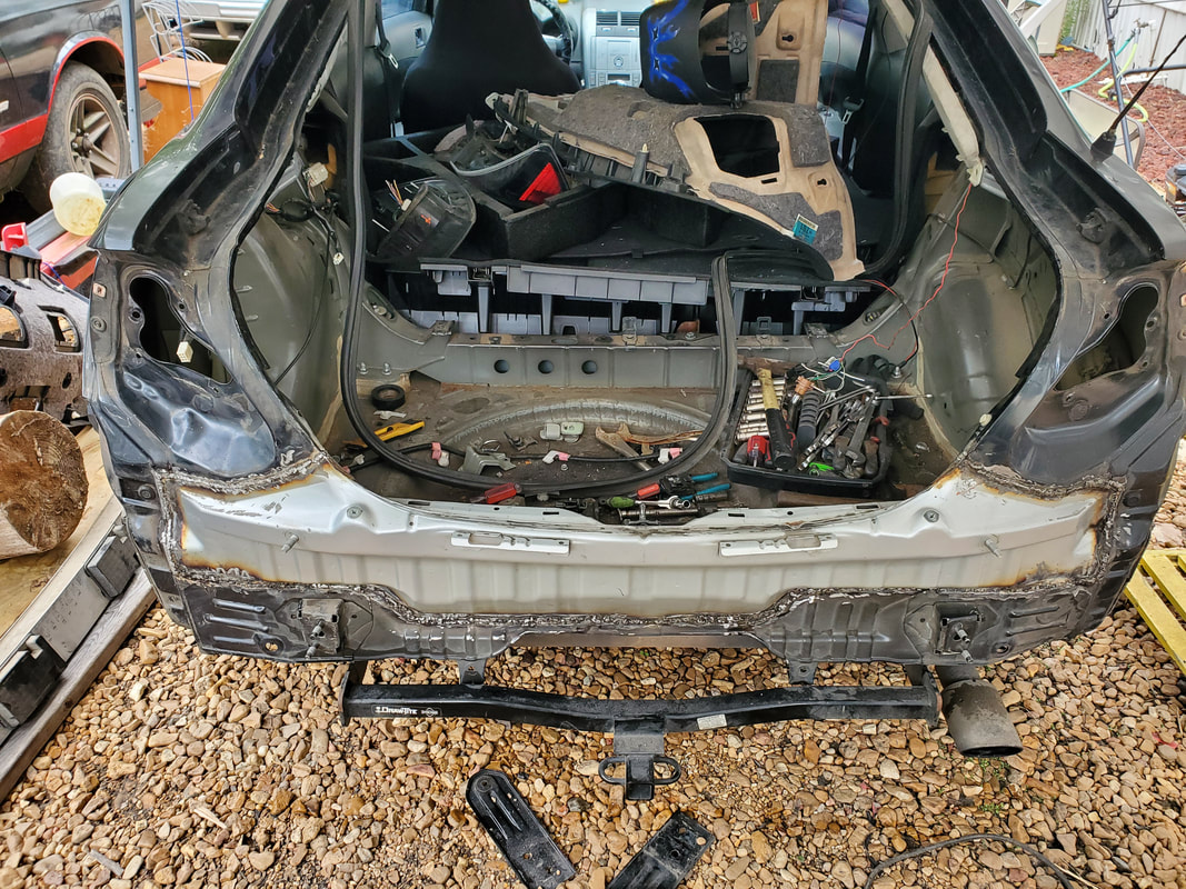 With everything removed once again, the replacement panel is fully welded in place. With the panel fully welded in place, I decided that it would only be right to paint the metal since there are a lot of bare metal joints in the form of weld beads and the ground down surfaces that were prepped before the welding. I spray painted the panel and the surrounding areas inside and out so we can at least preserve these metal surfaces from rust that would compromise the rear of the body in the long run. 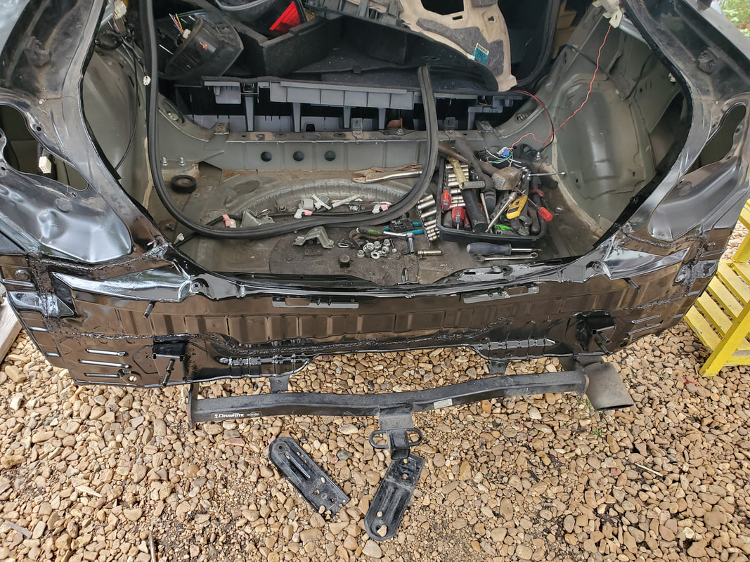 Body panel spray painted along with the surrounding area to protect the metal from rusting in the future. With the body panel all painted, the next move was to assemble everything. When I fully secured the taillights, I did find that they sat in a way where there was a minor gap at the top front of the taillights, due in part to the taillight panel not being perfectly lined up where everything would sit evenly all around. Its not for the lack of trying that this alignment couldn't be achieved, the pulling and hammering wasn't really enough to get the parts of the body to sit how they needed to sit to ensure this alignment. The impact distorted all the metal around the rear to where it is difficult to achieve this perfect arrangement of parts as they would need to be to be 100%. Anyway, I just started masking off the rear to spray some paint over the gray surfaces of the hatch and the bumper skin. I masked off the taillights, window and the other body surfaces in order just paint only the surfaces that need painting, for right now anyway. Once the paint was dried, I opened the hatch and sprayed paint around the inner edges that would be exposed after putting the interior panels in place. This would at least make things look less tacky. It would not look right with black surfaces on the outside and gray surfaces on the inside. I also took the time to install the switch panel from the old hatch as well as the third brake light and license plate lights, which I removed prior to spraying the hatch, as it would've been less to mask off. 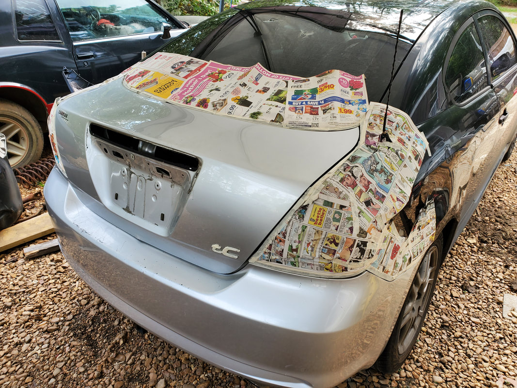 Body rear masked off prior to spray painting with some semi gloss from the rattle can. 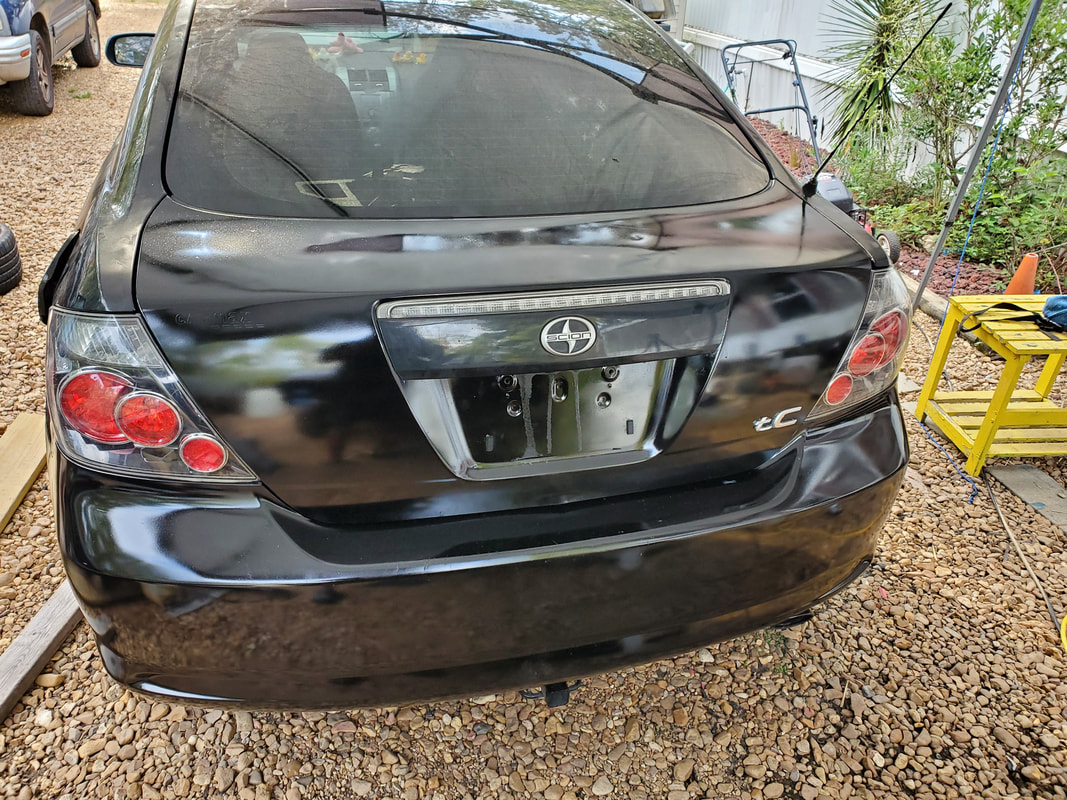 Rear after finishing the spray down with two good coats. Masking and paper are removed. With the rear done, all that's left is to install the spoiler from the old hatch, along with the backup camera that I installed a long time ago, then put all the interior panels back in place and clean everything up to complete the project. I might look at the taillights again later, removing them to see for shits and giggles if there is any possible way of straightening them out to close in those previously mentioned minor gaps. I won't be trying to hammer anything since I painted all the surfaces and I don't really want to compromise any of the metal any more than it already is by even trying to hammer anything - the same reason I really didn't go too much further in the beginning. These stamped steel components were already compromised and trying to do too much to straighten them out could've pushed me into the opposite direction where things would've been unable to line up because the metal was distorted to the outside instead of the inside from the original impact.
0 Comments
With the batch of junkyard parts in hand, the work can now begin to start reversing the damage caused on the Scion. The first area I have to target is the hinges for the hatch. Since they were distorted, I would have to first start off with straightening the mounting points out and hopefully be able to get the new hatch to set as intended. I tapped the bent up mounting points with a hammer and attempted to bolt the hatch down to see how things fit. 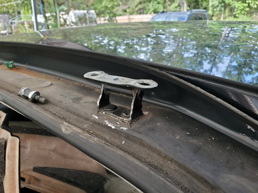 Right side hinge after a crude attempt to straighten out the top portion of the hinge. 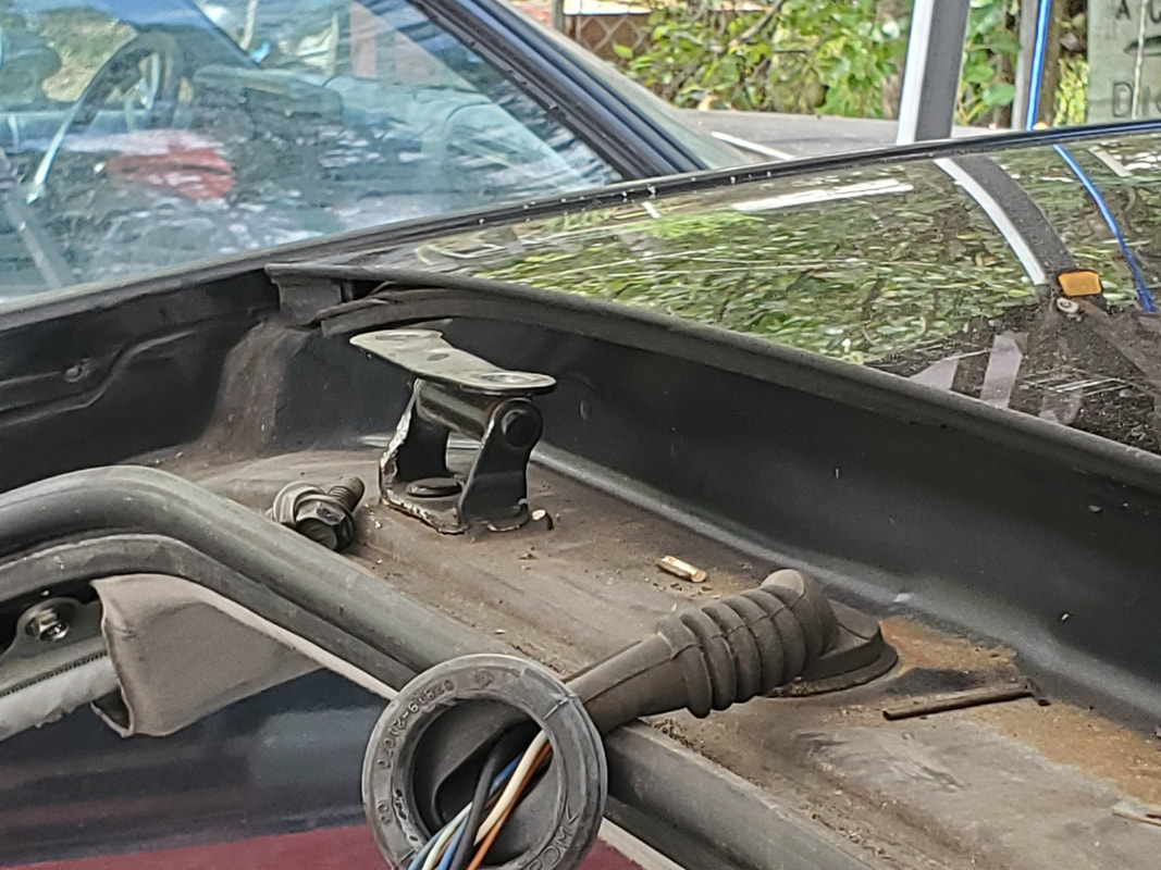 The same went for the left side, I don't see this working out all to well... The first attempt turned out to fail miserably. The front of the hatch sat too high, not even sitting flush with the sides, much less sitting at the right height to allow the hatch to open or close without making contact with the intermediate glass. This was no good. My next option was to take the hinges off and tap the bottom portion of each hinge, where it mounts to the car's body to try and straighten that part out. 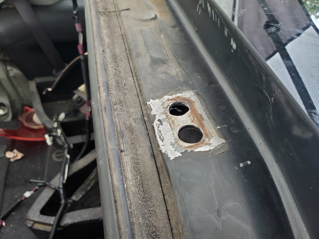 The holes in the top of the body where the hinges mount. At first I didn't know that the hinge was removable and had initially tried to straighten out the hinge by tapping the bottom portion with a large flathead screwdriver and a hammer. The way the hinge looked it made me think that it was welded in place but when I did some more investigating I found that the hinges were indeed removable. After straightening out the bottom portion of the hinges I reassembled everything and tried again. And again, it was a failure. The front of the hatch still sat too high and made contact with the intermediate glass. At first I wished I knew this when we were at the junkyard as I could've gotten the hinges from the junk car but after thinking about it, even those hinges might've sat wrong on this car since there were probably minute distortions present, even in the body, that would've made a different set of hinges not work. I had to come up with another option. That option would be to cut the bottom part of the hinges, trim the legs of the hinge to a shorter length then weld the bottom part back on. This would hopefully make the front of the hatch sit at a lower point on the body where it will clear the intermediate glass as well as sit flush along the sides as well as the front and back. 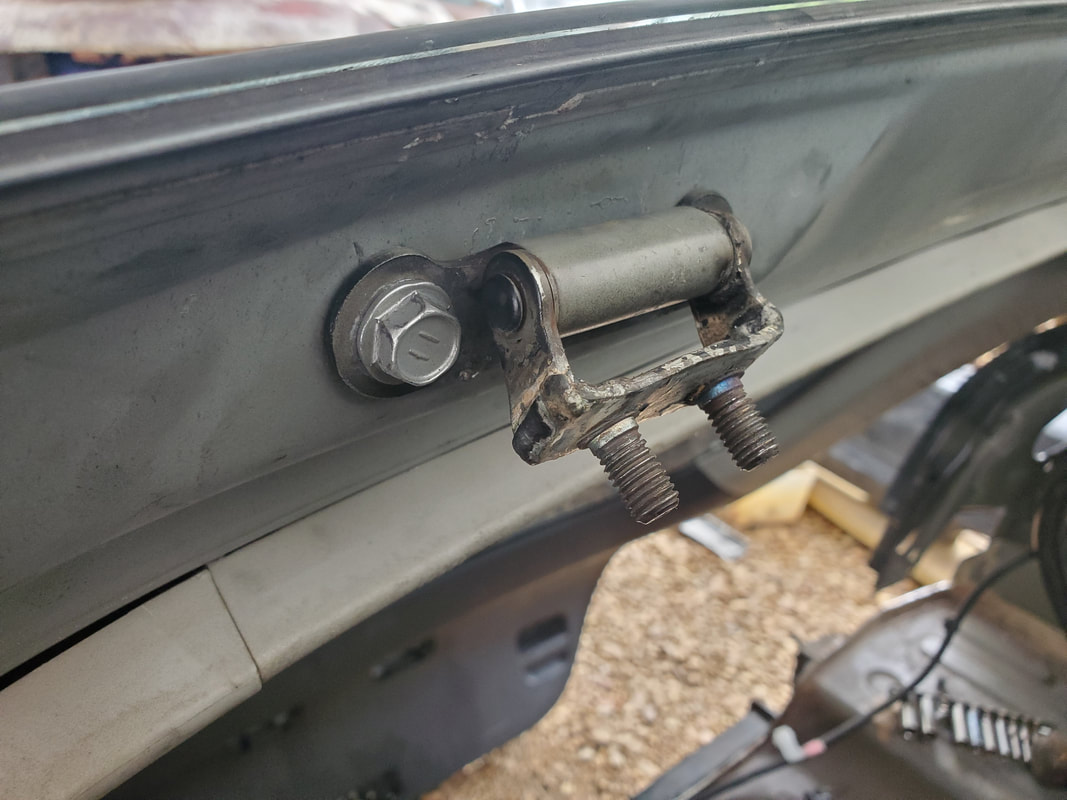 The hinge after cutting and shortening the piece and welding it back together. This turned out to be a success to a greater degree. The front of the hatch cleared the intermediate glass only slightly when the retaining nuts were half tight but once they were fully tight they still had some light interference. The last ditch effort I had was to remove the hinges once more, along with the hatch, and elongate the mounting holes on the body, with the emphasis on removing material going back, allowing the hinges to be mounted just a fraction of an inch to the rear. This move having me set the hinges back ever so slightly, was enough to allow the hatch to clear the intermediate glass as well as sit flush all around the sides and front of the hatch and the opening on the body. With this success finally in hand I can now move forward with the rest of the project. Widened holes where hatch hinges will go. This allows me to move the hatch back about 1/4" to allow the front of the hatch to clear the back of the sunroof glass. The first thing that I wanted to do was remove the section of wire harness that sits inside the interior trim panels of the hatch and connects to the taillights and hatch release. Since the car's wiring going to the hatch is all part of the greater wiring, I had to remove the section of wiring from the old hatch. On the junkyard hatch I just cut the wires at the hatch so I wouldn't have to pull everything apart while in the junkyard. Now I do have to pull the panels off on the junkyard hatch to pull the cut wiring section out and reinstall the old wiring on this new hatch. 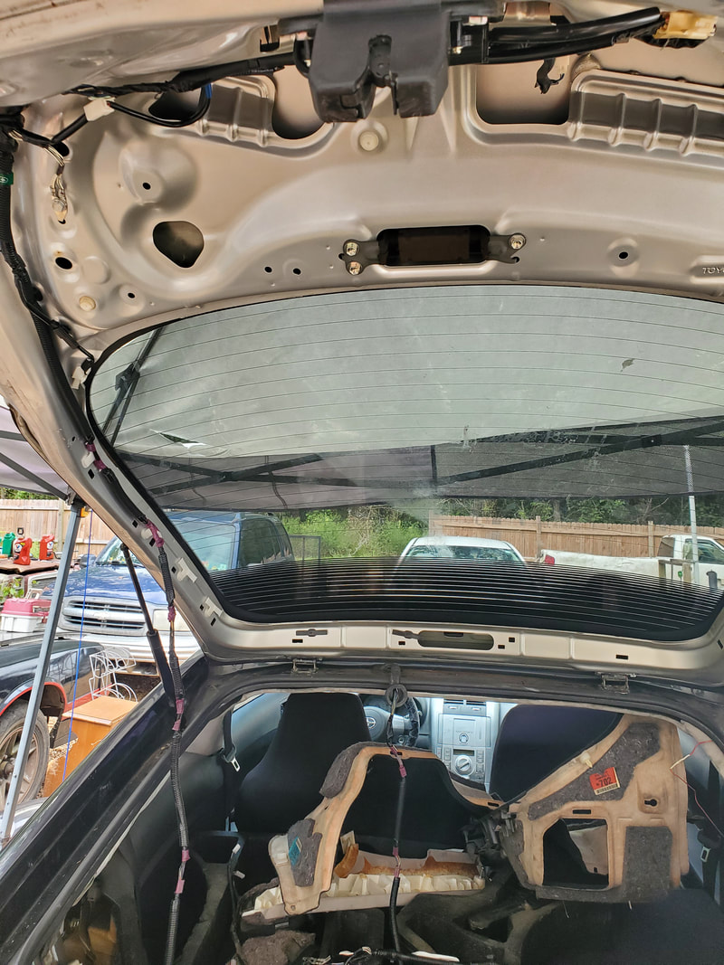 The old wiring harness that was left on the hatch after cutting the wiring to facilitate the hatch's removal. The wiring runs along the left side of the hatch, already partially removed. I took the time to snap all the retaining clips from the junkyard hatch to get the wiring harness completely removed. Once that was done, I took the car's original wiring, strung it through the opening at the front of the hatch then snapped the connectors in place along the left side of the hatch going up to the rear of the piece. Once there I was able to plug everything up and secure the ground strap. Since the new hatch is missing the cover that contains the hatch release switch, I left the covers off so when I pull the switch cover from the old hatch, I can install the piece on our new hatch. In the meantime, I can move on to starting the fitting of the body panel. 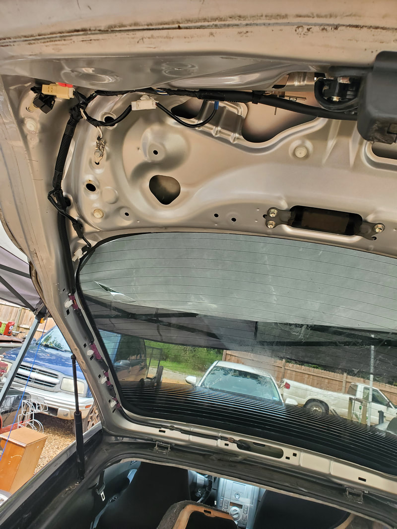 Car's original wiring routed through the new hatch and pegged in place along the left side of the hatch body and plugged to respective loads. I had to trim some of the excess metal from the edges of the panel piece as I test fitted the piece in place. Once I got enough metal trimmed off, I made a few tack welds to hold the piece in place while I tested out how the hatch closed on the piece, since this piece holds the loop that catches the latch on the hatch. The first attempt had the hatch close pretty good but the latch loop was a little to the right, causing the hatch to sit just a little high at the right rear of the piece. I ended up having to cut the tack welds then trim a little material to allow me to reweld the panel in place just a fraction of an inch to the left. Once this was done, the hatch closed smoothly and sat nice and flush. 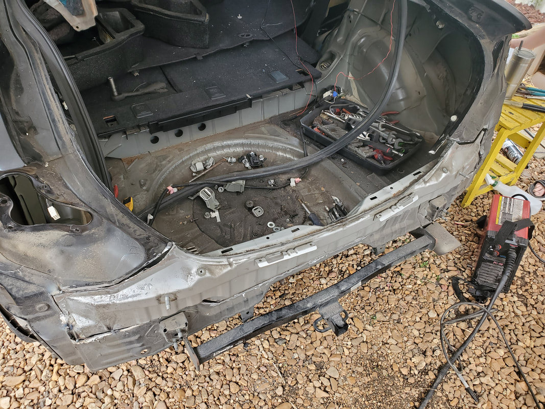 The patch panel tack welded in place to test fit it and the hatch before doing a full weld to the piece to seal it in. With the panel in place there's a couple mounting brackets that help secure the bottom ends of the taillight mount panel to the body panel. I have to check to see if these bracket pieces will line up where they can be fully bolted back in place. If that goes well, I can then further straighten out the bottom parts of the taillight panels where they will line up evenly with the top of the patch panel. I'll do a few more tack welds to hold these seams then test fit the taillights. Once that's all said and done we can fully weld everything up and finish up the assembly of the rear, which includes the bumper components and the interior panels that were pulled free to allow me to disassemble the body in the beginning. This repair is moving pretty fast so far.
With the Scion stripped down in the rear and our game plan laid out, the time came to hit the junkyard. Battery tools were packed and more than enough hand tools were packed to ensure an effortless chop job on the unfortunate yard car we hope to run across. Our first order of business was to get the hatch off. As with the old hatch, this required the both of us to do safely so my own members don't get damaged in case of an accident. Once the hatch was off, to give this hatch and its huge glass window a good chance of making it home in one piece, I used moving blankets, a bath towel and some old automotive carpet we took from the yard to cushion the trailer when we strapped down the hatch.
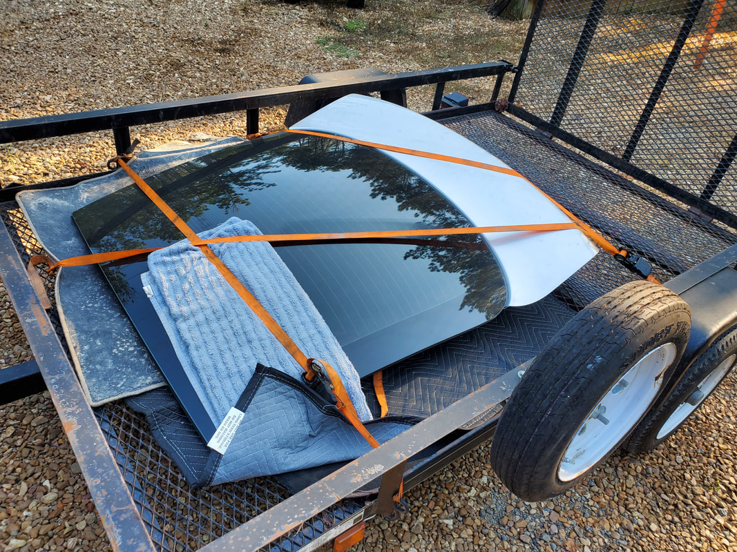
The new junkyard hatch, strapped down to the trailer with moving blankets, carpeting and even a bath towel to help cushion the piece to keep the glass from being shattered.
Unfortunately, the junkyard hatch was missing the panel that contains the switch that is used to release the latch mechanism. While this isn't that big of a deal and really something that couldn't be factored in given the fact that it was the only hatch available at the yard, I was able to rest easy with the idea that the old hatch's switch panel was still intact. I'll be able to pull this piece and install it on the new hatch, along with the spoiler I installed on our old hatch a while back. 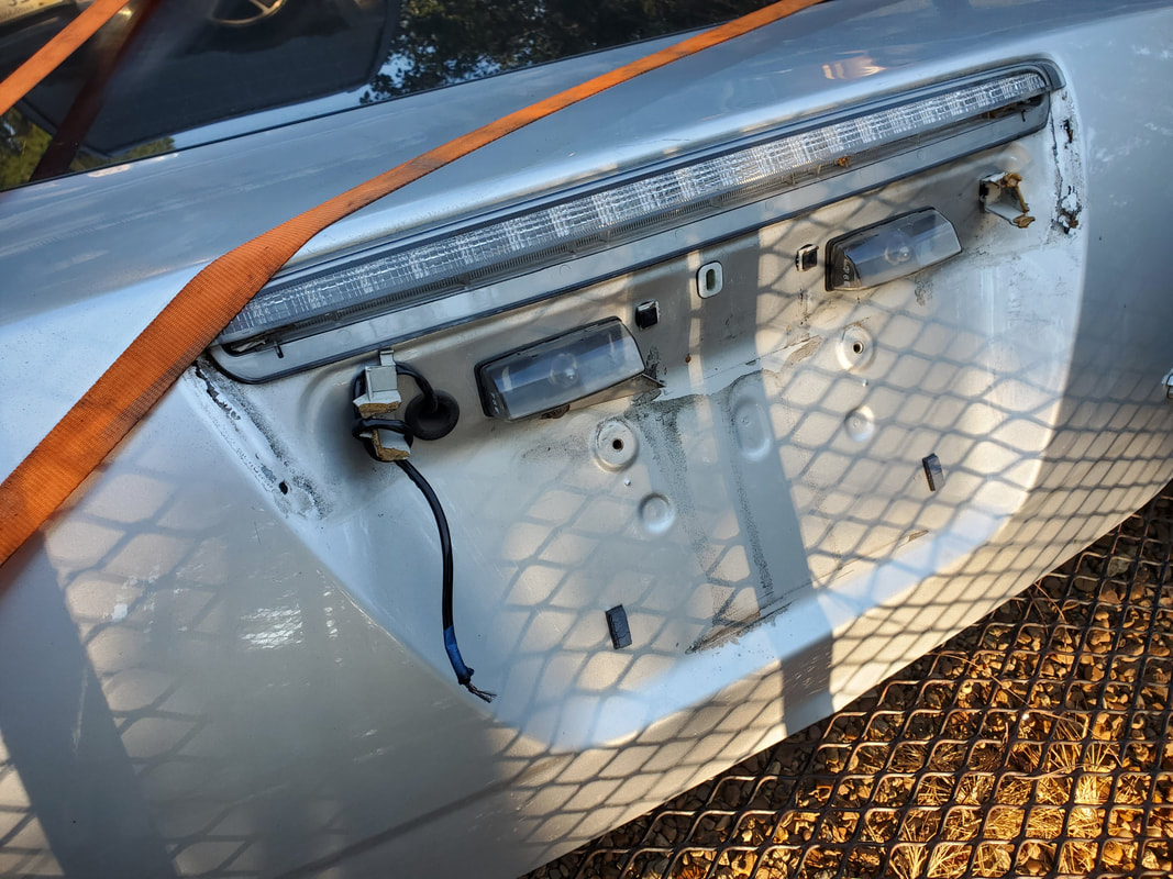
The switch panel was missing from this hatch but will be replaced with the unit from the old hatch that was surprisingly not damaged.
We also got lucky in the fact that the taillights on the car were also not damaged, save for one of the units having broken tabs at the bottom where they hook under the bumper skin. The main thing was the three studs that hold the piece to the body, those were still intact and should be sufficient to hold the light housing in place. The skin of both housings were intact and looked almost new. These may have been aftermarket housings used to dress up the car they came off of. Now they will help dress this car up. 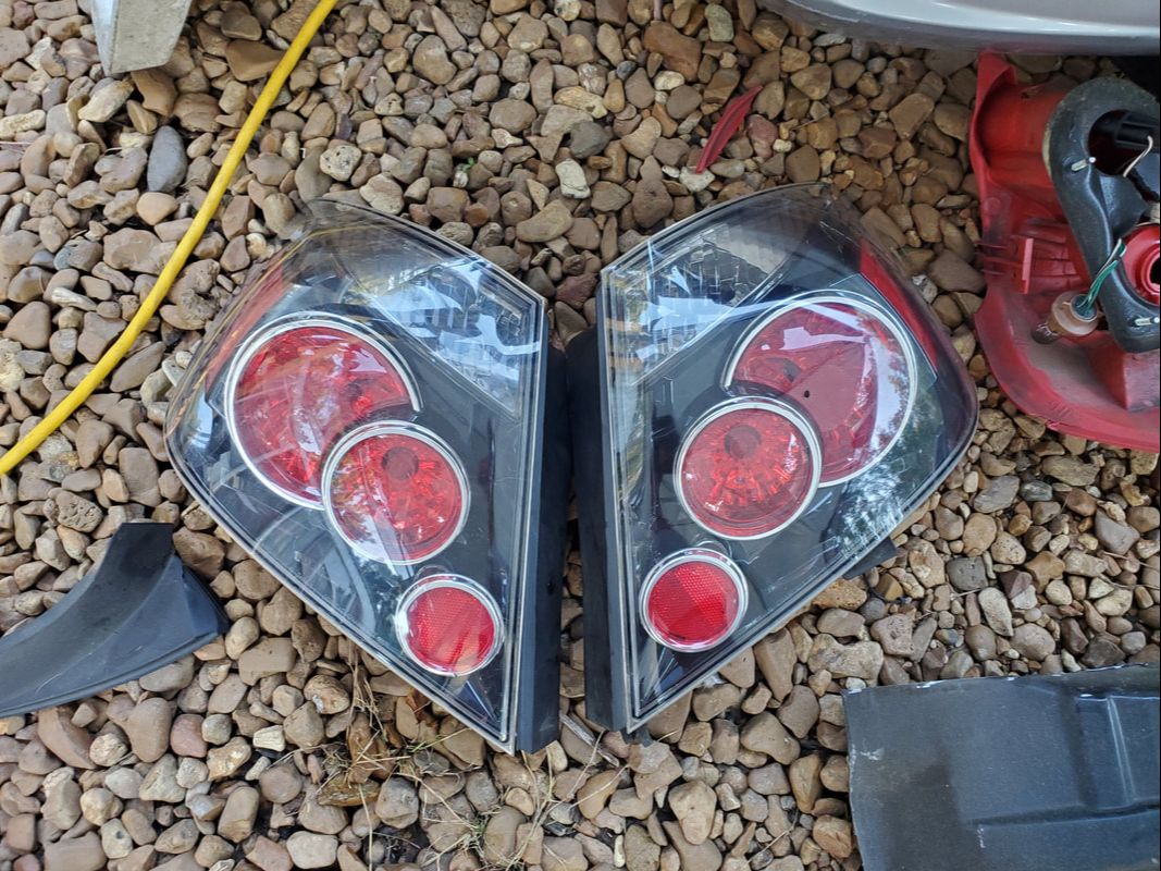
The set of replacement taillights pulled from the junkyard car.
We pulled the bumper skin, which was a light gray, so we'll have to spray this piece down to get it to at least sort of match the rest of the body. This will be accomplished with some rattle can paint, at least until I do other body repairs that would facilitate a full paint job, where I can then address the po' man's paint that will be done to the bumper skin as well as the hatch. In the meantime, along with the bumper skin, we got a foam pad that was still solid, save for one of the mounting nipples that protrudes from the pad and inserts into the metal bumper member. While this will make the foam piece unable to sit snugly on the metal bumper, I will just have to improvise to hold the foam pad in place so it doesn't have any play even under the bumper skin. I didn't need the metal member since our old unit was intact, but the member still had to come off in order for me to cut out the inner body panel section. 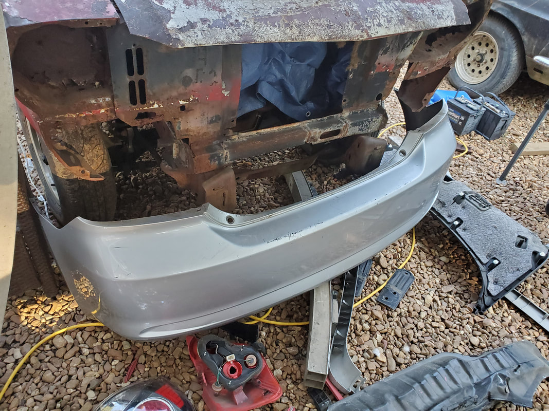
The replacement bumper skin removed from the junkyard car. This piece was in way better shape than our old piece.
The foam pad pulled from the junkyard car, note the two nipples at the top of the piece and the missing one opposite these at the bottom in the picture.
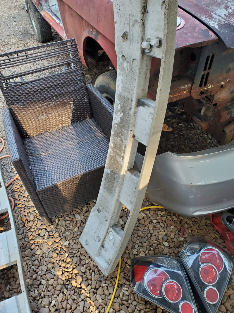
As with the old, damaged body member on the car, the junkyard car got the same treatment with the angle grinder and reciprocating saw, with me cutting the section of rear body out, taking the time to cut out a little further from the same lines I cut on the old panel. I wanted to make sure that there was enough metal available so I can make adjustments as needed and trim only what's necessary to ensure that the new panel fits exactly as I need it to so when its welded in, the hatch will close properly and all the other body components will fit as they're supposed to. 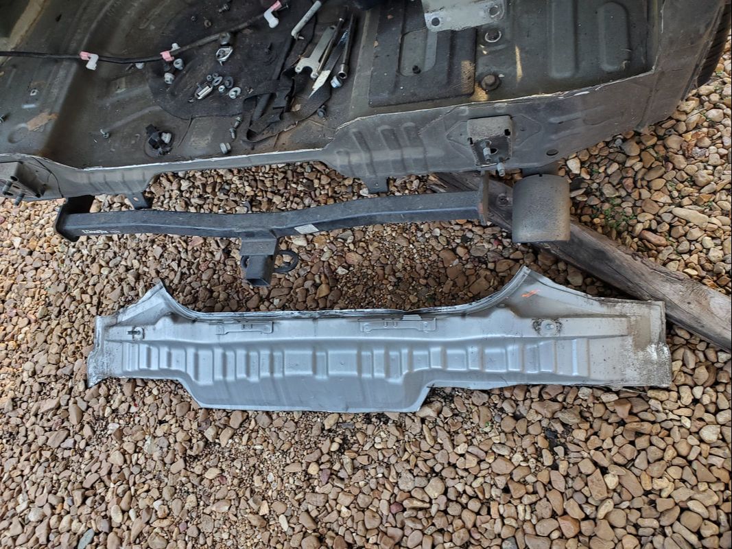
The replacement body member cut from the junkyard car and staged behind the Scion pending the installation.
With everything we need for the repair sourced from a single car at the junkyard, we can move on to getting this repair done and getting this car back on the road since this is a money making car and our time with the rental is limited. Once that goes back, the Tracker would end up having to be the money maker if my repair work takes longer than I anticipate, which it shouldn't since this appears to be a pretty simple job, all things considered. We'll get it done.
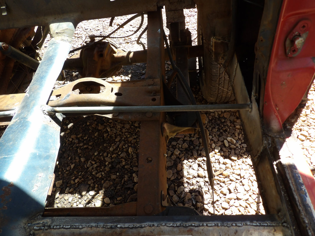
Well if trying to bring old cars back from the dead isn't bad enough, there's the matter of the occasional accident that occurs and takes an otherwise good car and turn it into something that also needs to be brought back. In our case, the Scion literally took one up the ass at a traffic light, causing damage to the rear hatch and the body member where the hatch latch is located. The taillights were destroyed just the same and the rear bumper and foam pad underneath were damaged. Surprisingly the glass that makes up 2/3 of the rear hatch wasn't shattered. The hinges for the hatch were distorted some. After all was said and done, we got the car back after the insurance people did their part since this thing's got a new engine among other things. I'm not giving money away like that. So while the lawyer people do their part, its time for me to get to work doing what we do around here, this time with the Scion. 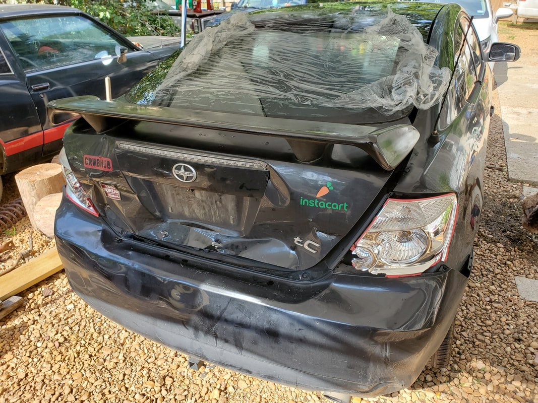 The damage to the rear of the car is pretty obvious here with the hatch and taillights taking the brunt of the damage. 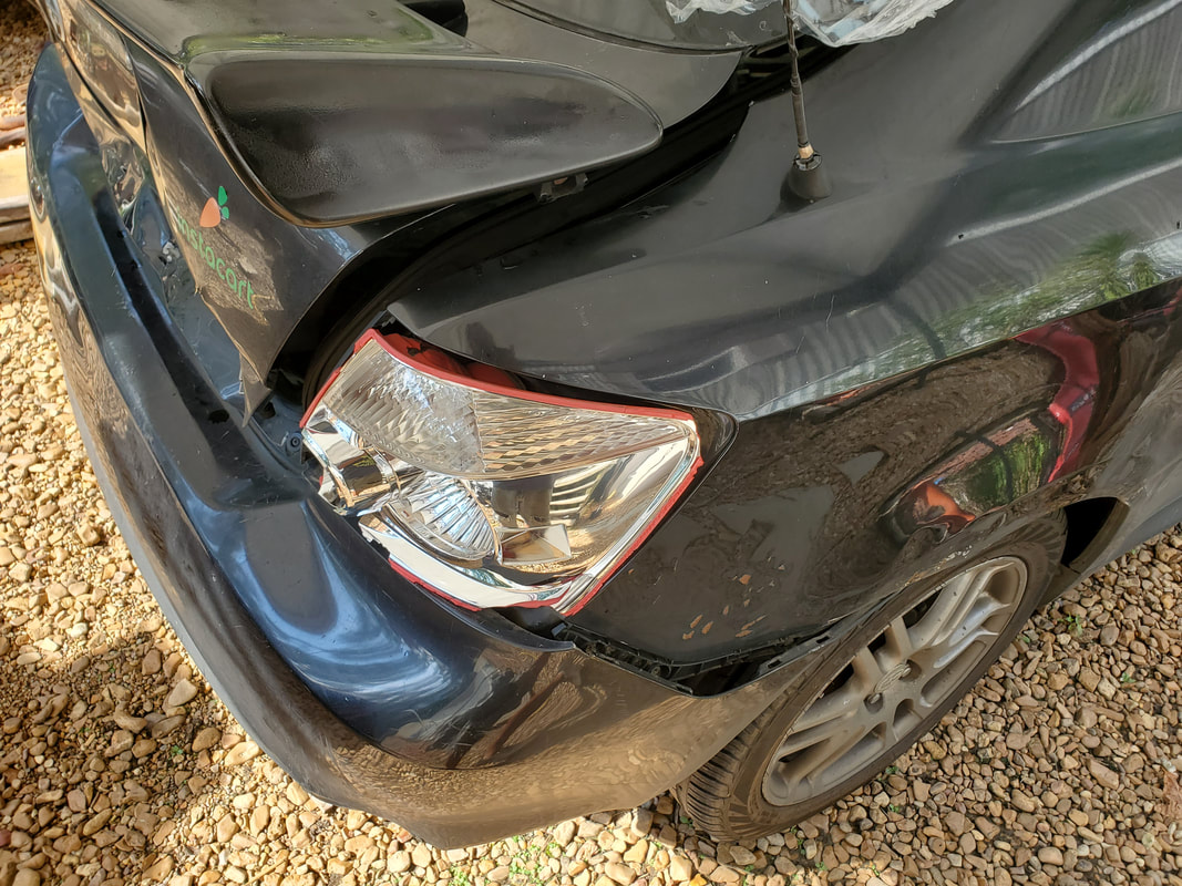 The right side showing the taillight and the way the bumper skin is distorted as a result. 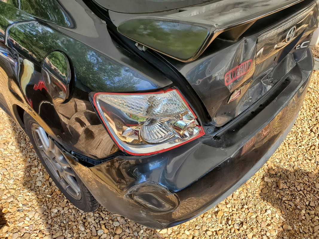 The left taillight didn't fare much better as did the bumper on this side. Surprisingly the subframe and floor didn't take any damage. The first thing I have to do is disassemble everything so I can get a good idea of what I'm working with. I had to start off with removing the hatch since this is the single most dangerous thing to deal with. If the shocks fail, this heavy piece will fall down and crush anything in its way. This of course took the both of us to do safely as I had to pop the shocks from the hatch then have my fingers under the pinch point that exists at the hinge area while removing the four bolts holding the hatch in place. It is here I found the hinges were damaged some. Hopefully I'll be able to just tap them back straight again without having to do anything else extra. I also had to pull the interior skin from the hatch so I could remove the entire wire harness from the hatch body, which was hardwired into the rest of the wiring. The hatch didn't have a removable wire harness so this is a dumb design in the electrical system. Once I pulled the wiring from the hatch we were able to completely remove the hatch from the car. 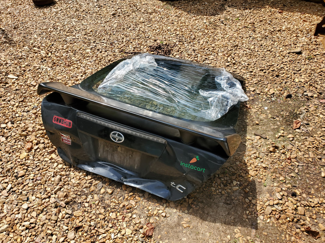 The damaged hatch completely removed from the car and taken out of the way. 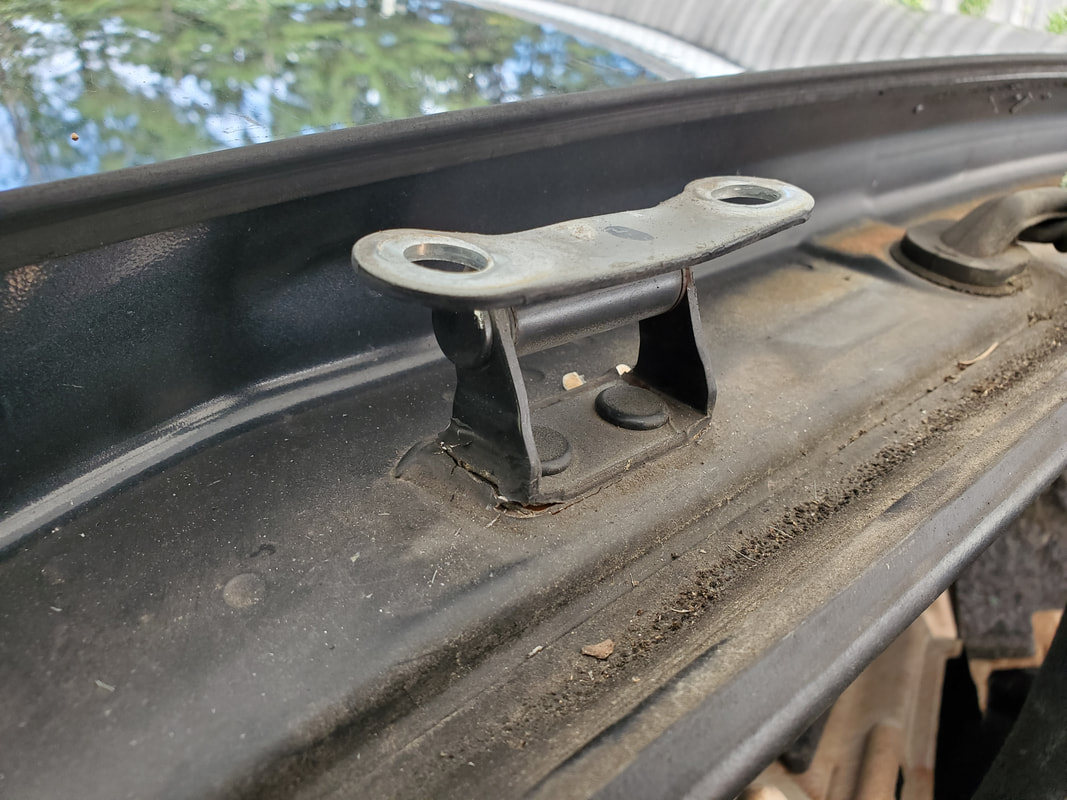 One of the hatch hinges that were distorted from the jarring of the impact, note how the portion welded to the body was pulled up some. 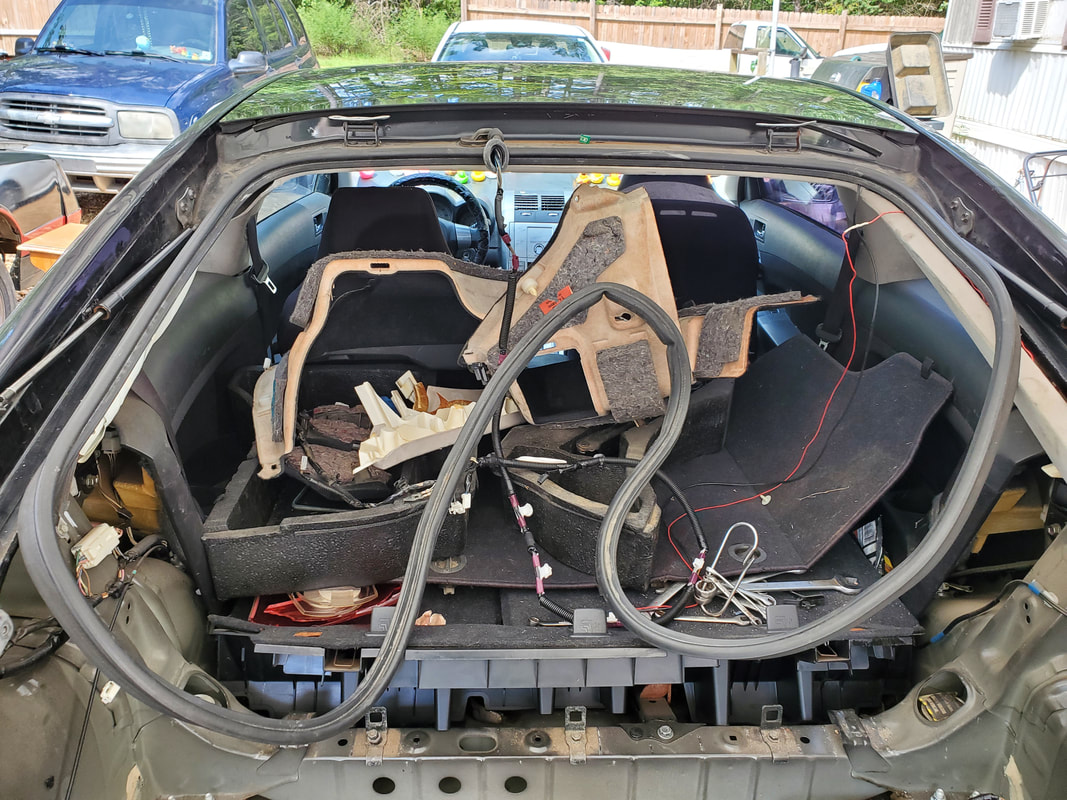 The interior full of panels and other crap removed to facilitate the removal of the bad components of the body. The next order of business was to remove the destroyed taillights. These are completely unsalvageable so once they came out they will be going straight to the trash. With that taken care of along with the two rear most interior panels that had to come free to allow me to access the studs on the taillights, I moved on to the bumper skin, bumper pad and the metal bumper member. 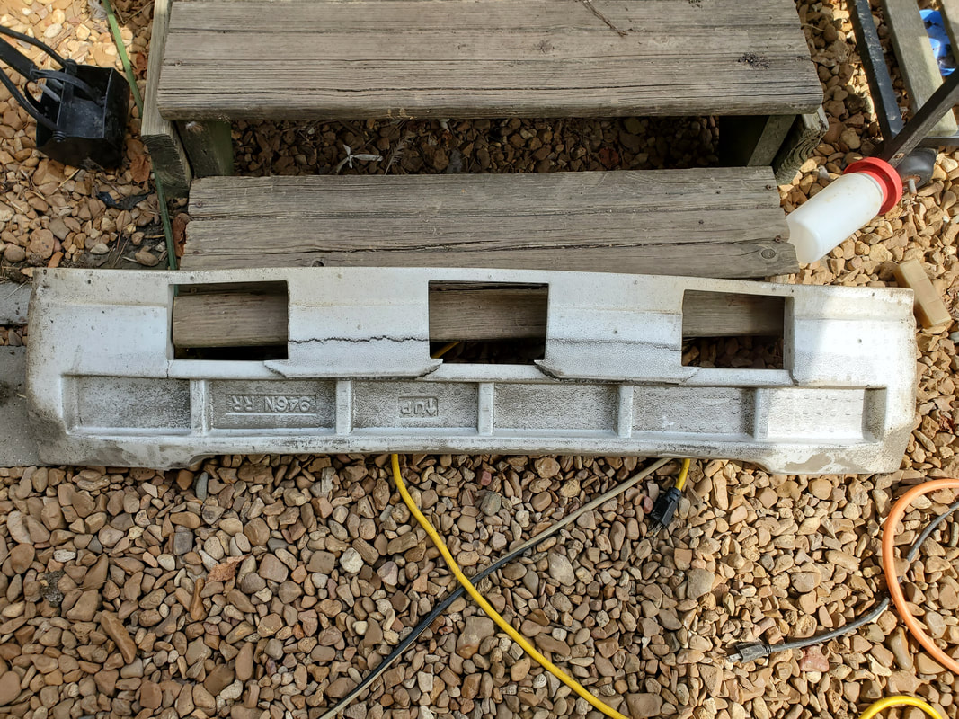 The bumper pad that took some of the shock of the impact. This foam piece helped cushion some of the blow enough that it didn't distort the metal member it was attached to. The bumper skin wasn't really damaged for the most part, the plastic clips and protrusions that hook to the body to hold the piece in place were still intact. This bumper was already compromised from a previous impact but since we're making repairs, it's only fitting to just go ahead and replace this mess so we aren't sitting here trying to use a heat gun to work out the dented plastic. After pulling the foam pad I removed the metal inner bumper that actually can be considered a bumper in the old terminology. This member was intact and not distorted in any way, which is good, one less component we'll have to source. 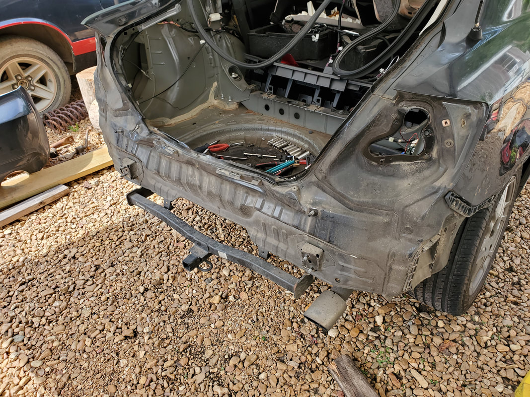 With all the bumper components removed, I can survey the scope of the damage to the rear body panel and determine what I want to do. After looking at the rear inner body panel that was exposed once the bumper components were removed, I determined that it would actually be easier to just cut out the section of the inner body along the seams where the components were spot welded together and cut the same section of body out from a junkyard car and weld this metal back in place. This is the same thing I had to do to the Tracker a year ago when that car was damaged. Since the body members were made in a way to allow me to use the grinder to cut out a large section of the rear pretty quickly, this was a more viable option than trying to hammer out the old body member and hope to have it be straight enough that everything would go back together properly.  The rear after cutting out the inner body member that was damaged. 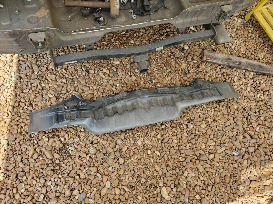 The section of crinkled metal body member that was cut out and will be replaced by a similar piece of metal cut from a junkyard car. With everything removed that I needed to remove, the next move will be to hit the junkyard and try to source all the parts we'll need to make the repairs to the car and bring it back to the state it was in before the accident. I may even feel compelled to do some other repairs to the rear quarters with these extra repairs being done since I would have to restore all of this area before we could ever consider getting a rebuilder's title for this car again. We'll see how that works out to determine if that's even an option later. In the meantime we need to hit the junkyard. Since a lot of modification was made with the floors in the body, the concern was always at the back of my mind about how the interior panels and rear seats would fit in the body. Since the floor for the most part rides a lot higher than the old floors, I already figured that I would have to do some modification to the two side panels that grace either side of the rear seat in order to make them fit. Now, some would cringe at the thought of cutting up a set of vintage interior panels versus just making some kind of improvised panel but the intent is to try and restore as much of the car as possible and this includes the interior panels. So hacking it is. 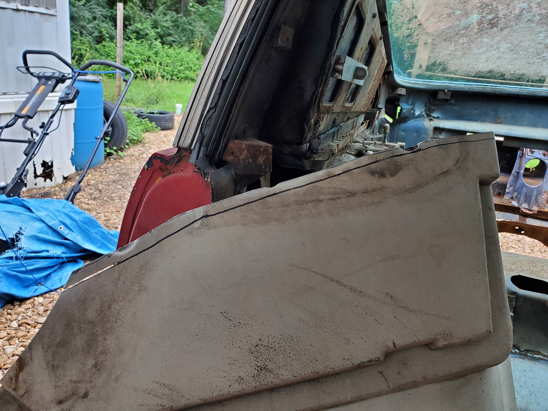 Marks made on where cuts need to be made to trim enough of the bottom of the panel to allow it to fit. 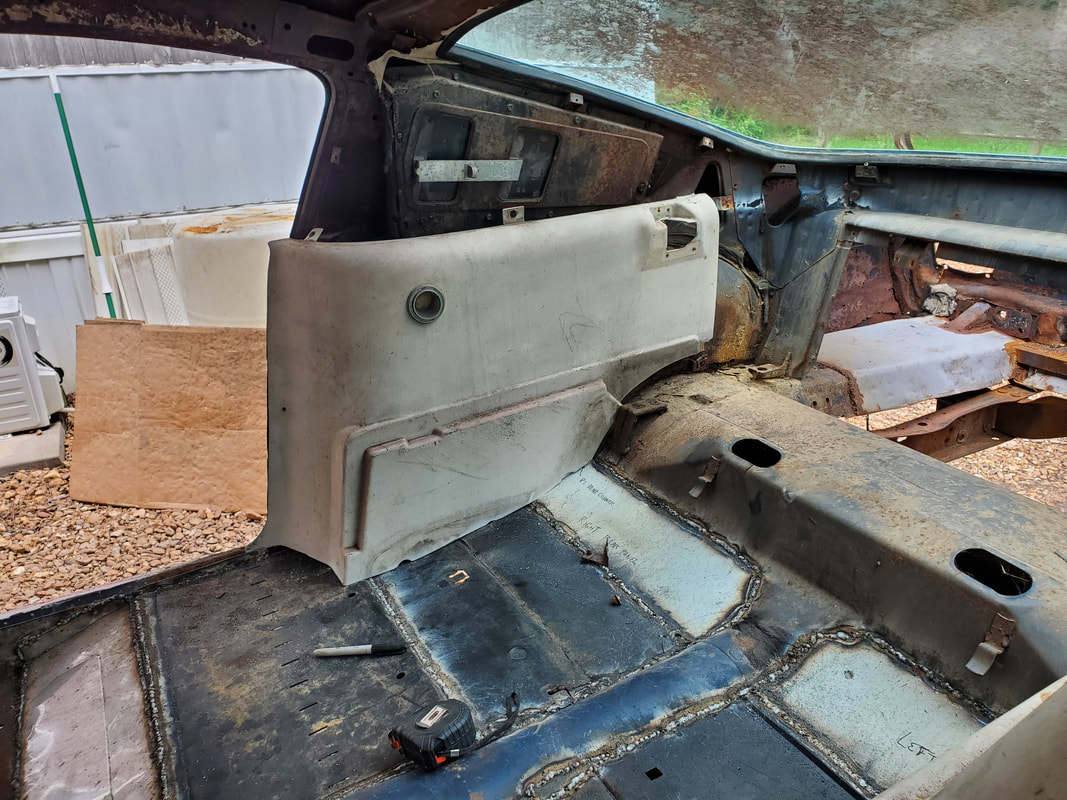 During the first fitting after making the initial cut of the bottom of the panel. Note how the top is setting higher than where it needs to go. I had already eyeballed where I would need to start and even measured from one of the screw holes at the top of the panel down to where the new floors are at to get an idea of where to trace a new line along the bottom. I cut out some of the plastic and did some test fitting, then from that point on did a series of small trims, eyeballing where the bottom was making contact with the floor so I can trim out just that small amount of material. I didn't want to just cut out a bunch of material then find out I cut too much plastic. Doing that would have the panel fitting where there's huge gaps along the bottom, which would just look tacky as hell. Once I finally got the panel where it was actually fitting good along the bottom as well as lined up with the top screw holes, I was able to move on to finalizing the mounting of the panel. 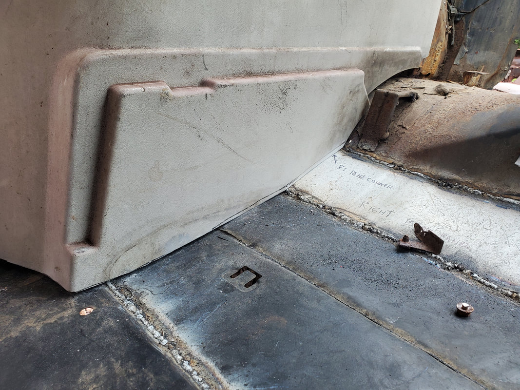 Closeup of the bottom of the interior panel as I did the final fitting before securing in place. One thing I also took time to address is the interior light in the panel. These lights always gave a warm white glow when they were activated and it would be cool to restore operation of these lights, even if I upgrade to LED bulbs. The terminals used the male/female bullet plugs which rather than try to use, I just cut those ends off and spliced a pair of wires to the wires for the light sockets, then strung the wires down to the bottom front of the panel so when I rewire the car I can splice into these wires for the interior light circuit. 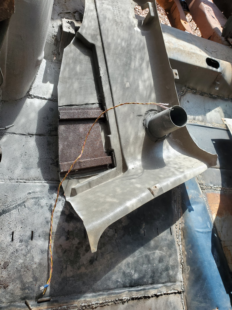 Light socket with pair of wires spliced to ends on socket so the piece can be wired up later when the car is rewired. 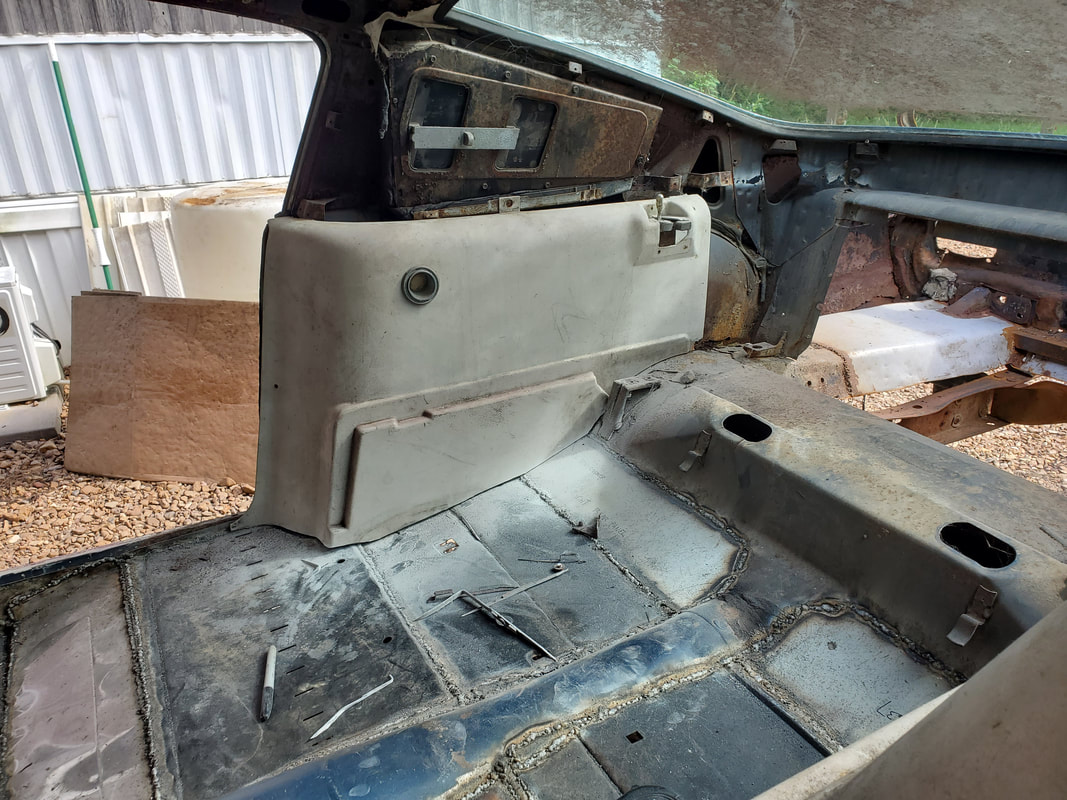 Panel as it will sit when fully secured in place on the side. With the light wired up, I added the screws where there were still mounting points. Along the bottom though, since the mounting points were all cut off during the trimming of the bottom of the panel, I had to come up with another idea. I took a small angle brace and drilled a hole on the bottom of the panel. I used a small nut and bolt to hold the brace to the bottom of the panel. I then drilled a hole on the floor so the brace can be secured using a sheet metal screw, effectively holding the bottom of the panel on the floor. With the right side interior panel done, I moved to the left side to do the same. 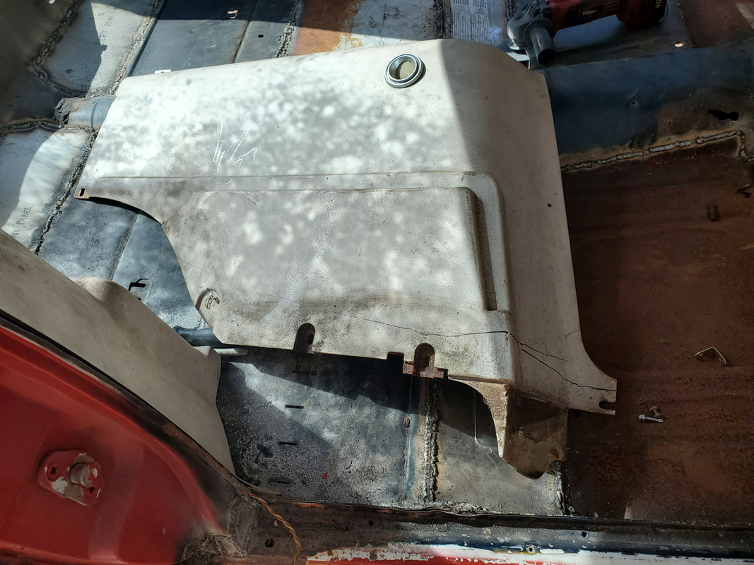 Left side interior panel in its original form before cutting. Note the marks made for where the first cuts will start. After doing the right side I had a good idea on where to start with the trimming. I started off with a line marking where my first cut would be and did the chop. After fitting the panel I only had to do a couple small trims before I had the panel right where I needed it to be. I was able to secure the angle brace in place, splice the wires and mount the panel in place as I did on the right side. 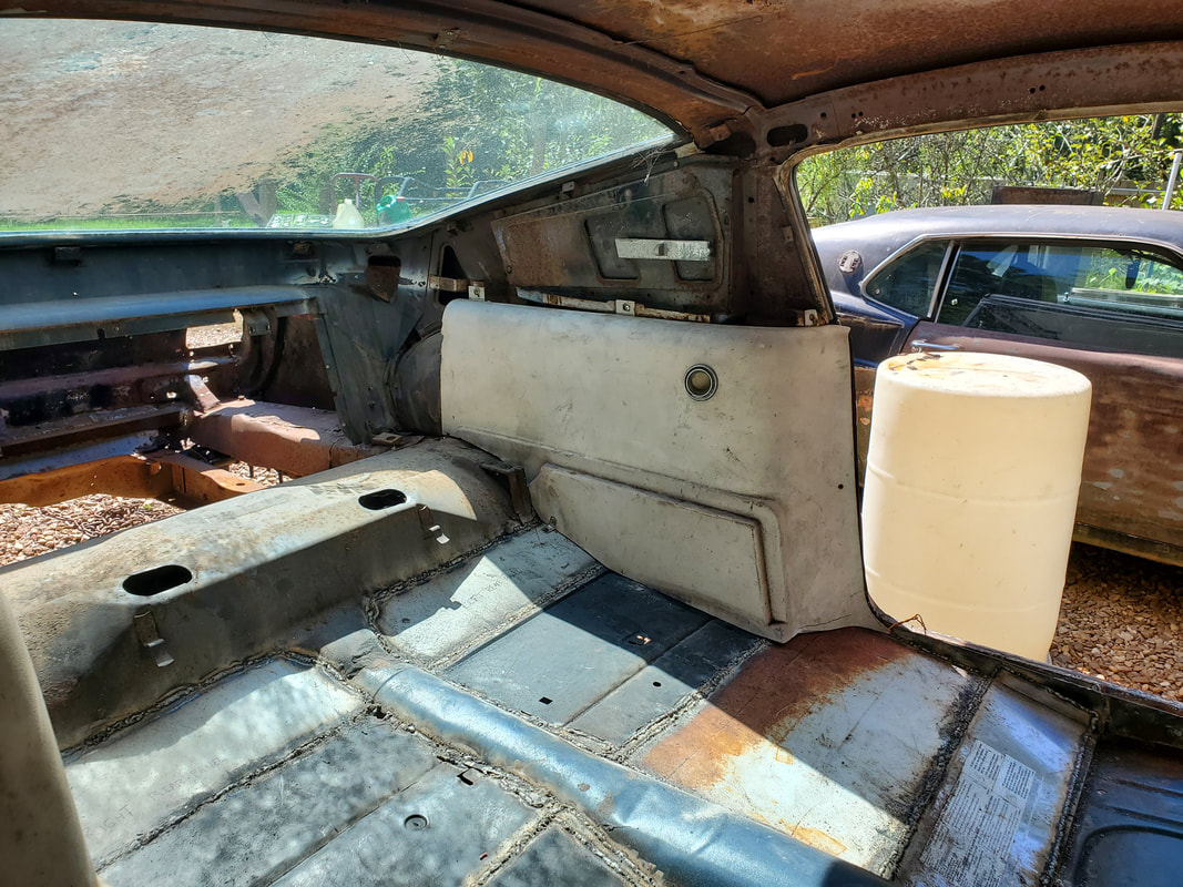 Left side interior panel installed on the body with the small angle brace at the bottom rear to hold it in place, same as the right side. With the two interior panels mounted on the inside, I eliminated a concern I had about fitting some parts that I had to reuse but would not be able to use in their original form. I could go further off on a tangent and assemble the rest of the interior around these panels but to try and stay on script I'll be moving back to the outside and continue assembling the body. We have several parts that make up the "front clip", which I really want to try and make one piece if possible. Here I will probably find myself doing more modification to these parts to allow me to connect them to each other in a way that will allow me to mount the whole assembly as one piece versus having to put the pieces on one at a time in a sequence.
With the front third of the floor done and the angle iron supports and final set of body mounts taken care of, its time to start coming around the bend to the finish line with the completion of the Mustang's floor. Just as was done with the angle iron for support with the sheet metal, I decided to add some supports in the form of old conduits that will aid in supporting the sheet metal when its added. The first thing I did before this though was close in the narrow middle section of floor between the two angle iron supports. This section is a 7" gap between the two angle iron supports, easily filled in with pieces of scrap sheet metal.
Small piece of sheet metal welded in place between the angle iron supports on the passenger side.
Small section of sheet metal welded in place between the angle iron supports on the driver's side.
With the smaller pieces of sheet metal completely welded in, fully closing in the angle iron supports, I dug out some conduits and mapped out the spots where I want to weld them in place. I prepped the metal with the grind down to bare metal then cut the lengths of conduit I needed. I started off with the first set of conduits, about a foot back from the angle iron supports, welding them in place just in front of one of the crossmembers of the Ranger frame. The placement of these conduits will allow the sheet metal to rest just above the Ranger frame rails and crossmembers. 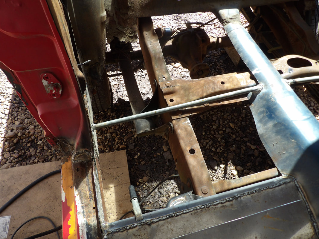
Passenger side conduit welded in place just in front of the Ranger frame crossmember.
Driver's side conduit welded in place just in front of the Ranger frame crossmember.
With the two pieces of conduit welded in place, I moved on to the last set of conduits to go across the rear section of floor space. Because of how the driveshaft hump is cut pretty small in the rear area, I decided to just make the conduit support extend across and under the hump to the other side. To make this happen easily, I took a piece of 1/2" conduit and 3/4" conduit and slid the smaller into the larger and welded the set of pipes in place between the tire wells. I welded the center of the pipes to the driveshaft hump then finished up with a weld where the pipes slide into one another to complete the whole set. 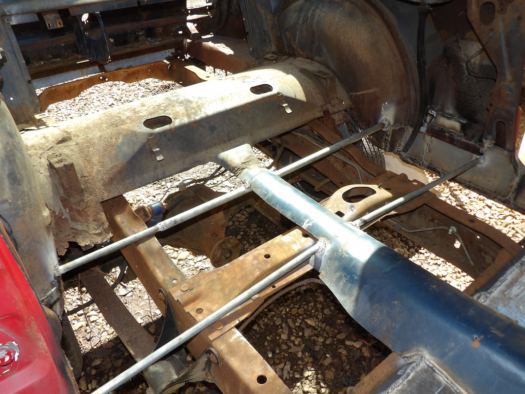
Rear most conduits made up of two different sized pipes slid into one another and welded in place across the floor and under the driveshaft hump.
With the conduits all in place, I did some final grinding of the surfaces where I'll be welding the sheet metal for the flooring. Going around the tire wells and the edges of the old flooring I got the old paint and rust ground away. I just need to cut some pieces of sheet metal scrap to fit into these sections so I can start welding metal in place. It'll be easier to split the flooring into smaller sections, much like a sidewalk being split into slabs so the floor won't flex and make noise in the cab, plus the extra welds on the conduits will add to the overall support of the floors. I did bring the two interior panels that go in the back seat area and size them up to see what modifications I'd have to make. I did find that I'll only have to trim the bottom 6 inches of the panels off to fit them in place after the new floors are done, which isn't too bad. As for the back seat, it's not really looking too good but then again who knows, things sometimes have a weird way of working themselves out in the end....
With the crude body repair taken care of and the internal structural repair done on the inner rocker panel area, I was finally able to add the angle iron supports that I intended to add. I needed the inner rocker panel metal in place to give me a surface with which to weld the angle iron to. Since I couldn't get any angle iron that was long enough to span the gap from one side to the other and go through the driveshaft hump, I ended up just using 2 ft long pieces that would be welded to the outside of the driveshaft hump and the inner rocker panel metal. The first set of angle iron pieces were welded directly to the rear of the seat mount panels to aid in reinforcing those panels so when the seats are in place, the panels won't flex excessively. The second set of angle iron supports would go over the last set of body mounts on the Ranger frame. Before I could fully weld in the last set of irons, I had to line up where the bolt that would pass through the body mount needed to go on each angle iron piece. 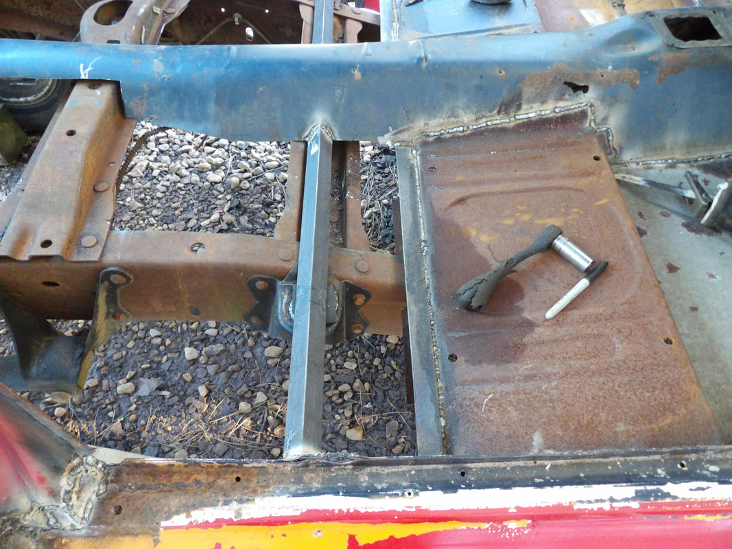 Passenger side pair of angle iron supports welded in place against the driveshaft hump, seat mount panel and inner rocker panel. To make the angle iron be able to go in place without it interfering too much with the floor pans that will also go in afterward, I situated the irons in an A position with the corner pointing up. I ended up welding in a washer to the spot over the body mount, then welding the bolt to the washer. Once this was done I welded a large washer to the body mount bracket. I was able to position the angle iron piece over the body mount, using a piece of cut rubber radiator hose to serve as a washer/cushion between the angle iron and the body mount. I welded the angle iron in place and secured the bolt with a washer and nut to complete the attachment to the Ranger frame body mount.  Closeup of the rubber washer/cushion placed between the angle iron and body mount to separate the two metal members. 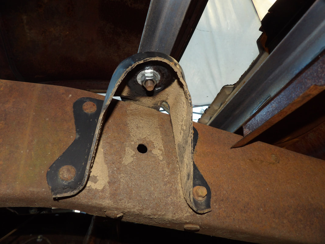 Nut and washer attached to the bolt that's welded under the angle iron support piece. The large washer is also noticeable under the body mount. Both sides were done in the same way with the angle iron so with that the last set of body mounts were addressed, along with the reinforcement of the seat mount panels on the body. This section being centrally located, will add to the reinforcement of the body and its attachment to the truck frame while also giving the front seats the added support they'll need to be safer to use compared to if the seats just sat on the seat mount panels by themselves. A short piece of sheet metal will be welded between the angle iron supports to close in this section of flooring. The smaller pieces of sheet metal will eliminate the flexing issue that has been a concern of mine with the floor repairs on this body. 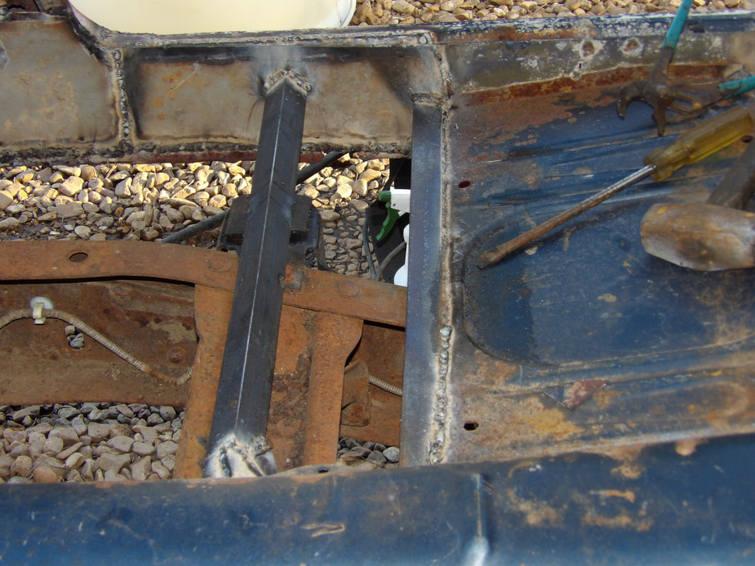 Driver's side angle iron supports welded in place to the inner rocker panel metal and the rear of the seat mount panel. Also note the body mount with the rubber cushion in place. 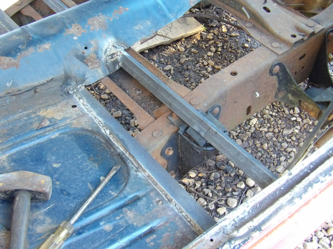 Shot of driver's side angle iron supports where they weld to the driveshaft hump. I needed to add a little piece of metal on the rear most angle iron piece to fill a gap on the cut that was made to accommodate the angle iron piece. Once the sheet metal is welded in place between the angle iron supports, I can start figuring out how I'll get the final section of flooring done going into the rear seat area. I'll probably end up welding in some supports to divide the open space into sections so instead of one huge piece of sheet metal going in place over the open space, it'll be a set of smaller panels going in, each attaching to the supports on either end. This will lessen the likelihood or severity of the flexing issue and the resulting noise while giving the floor of the car the strength it needs to be able to support our weight while either sitting in the car or crawling around in the rear to move things around. I'll have to bring out the interior panels that mount on the sides where the rear seat goes in order to see how much of these panels I'd have to trim off to accommodate the higher floors in the rear. Hopefully I won't have to trim too much material from these. I also still have to see if its possible to use the rear seats... In order to add the angle iron on the left side behind the front seat floor pans I will have to repair or more accurately, replace the metal that makes up the inner rocker panel (or whatever the hell this particular structural member is called) metal. The left side is worse off than the right side with a large majority of the metal just gone from rust. I had a couple large pieces of rigid sheet metal that were perfect for this application due to their being stiff enough to almost make a good frame repair patch. I cut a couple pieces of the metal to span the length of the rocker panel area going from just about behind the front seat floor pans all the way back to the rear quarter tire well. 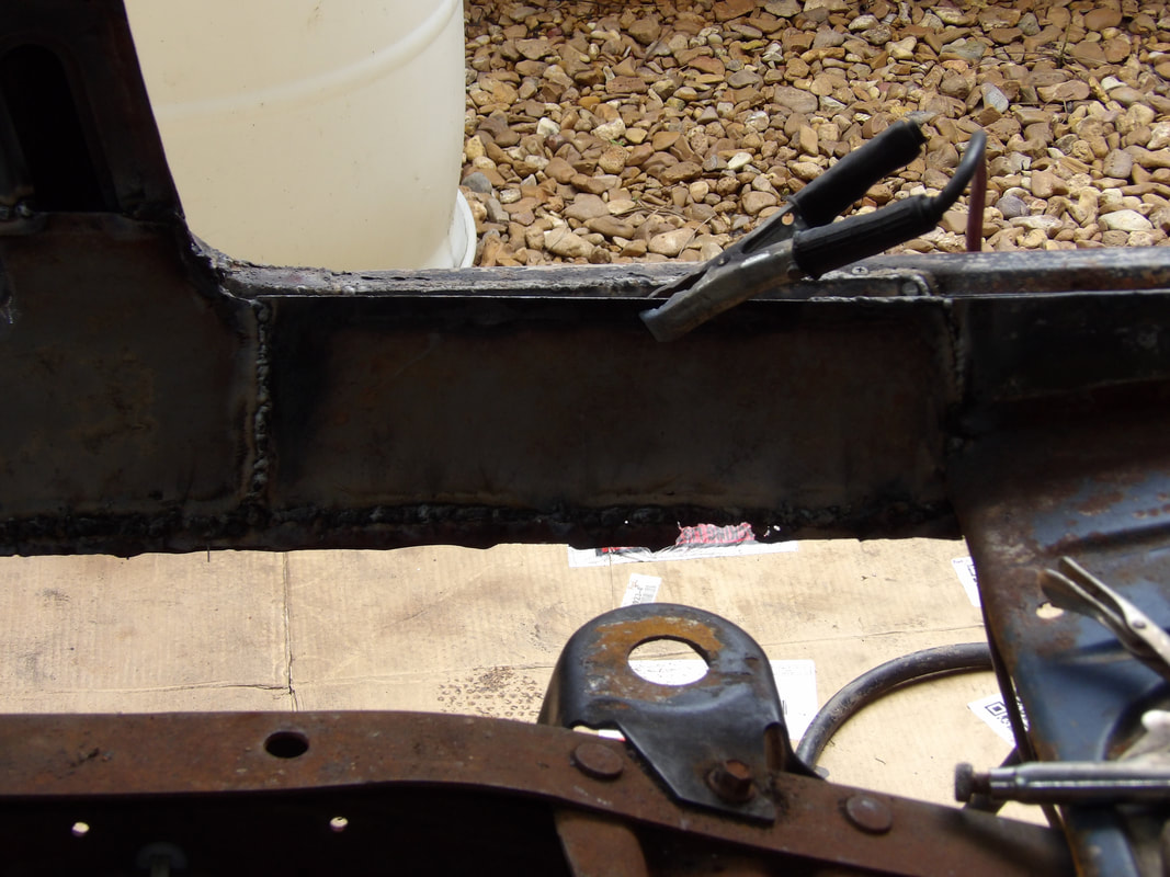 First piece of rigid sheet metal welded in place just behind the front seat floor pan to fill in these rotted areas. This stiff metal will provide a solid surface to weld the angle iron to in order to further strengthen the central floor area as well as fill in the areas that were vacated by the rusted metal. Connecting the new metal to the old metal also gave the added bonus of adding restored strength to the rear quarter/tire well/rocker panel junction, which will need some extensive repairs due to extreme rust and degradation from previous body repair, which incorporated a heavy use of body filler, all of which is pretty degraded due to the moisture and rust. 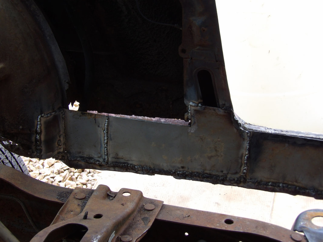 The second section of metal welded in place to connect the inner rocker panel area to the tire well and the door jamb section going upwards. Another area that I had to address was the little wire channel that goes along the top of the rocker panel area. The narrow molding chrome piece that sets on this area covers this channel. A section of this channel was rusted out as well and needed to be replaced with some more scrap metal. I welded in the replacement channel piece and some other metal at the rear of the corner of the door jamb. With this metal all done, I did another detour to the bottom of the rear quarter. This area is a train wreck just as well. 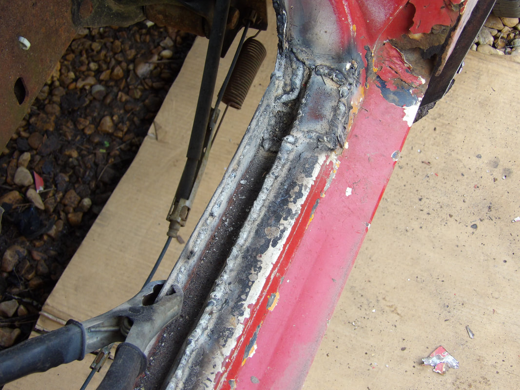 Scrap metal welded in place in the wire channel portion of the body. Note the rot along the door jamb working its way up. The rocker panel to rear quarter area is extremely rotted out. Now normally this would've been replaced with a whole new rear quarter but this isn't a viable option at the moment so the next best thing is to weld in some sheet metal then fill the area with body filler to smooth everything out. I had to grind out some old body filler and rust to prep the area then cut a piece of sheet metal that I would install behind the rear quarter. I did a series of light welds on the lowest setting so as to not vaporize the thin metal. Of course as I super heat the metal, the body filler got even weaker, allowing me to peel a lot away, exposing more area that will have to be covered up afterward. To further reinforce the metal patch inside the quarter panel, I did a series of welds along the surface to have more anchor points. As I peeled away filler plugs, I exposed more area that'll require more metal patches on the inside. Of course when its all said and done, the inside of the quarter will look like a patchwork just like the floors. Of course the body filler will cover all this fuckery up to make things look at least somewhat decent from the outside. 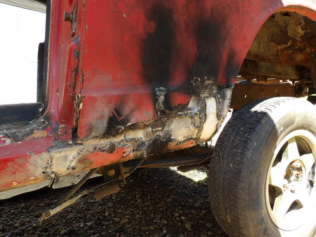 The crude sheet metal patchwork done on the rusty once bondo covered quarter panel, forward of the tire. All of the weld slag will be ground down as flush as possible in order to apply new bondo to hopefully make the area smooth again and looking somewhat decent. 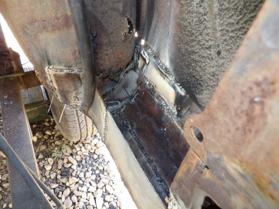 Inside of the quarter panel showing how the sheet metal patching was welded on the inside in order to make the patches be recessed so when bondo is applied, it can be smoothed down easier. 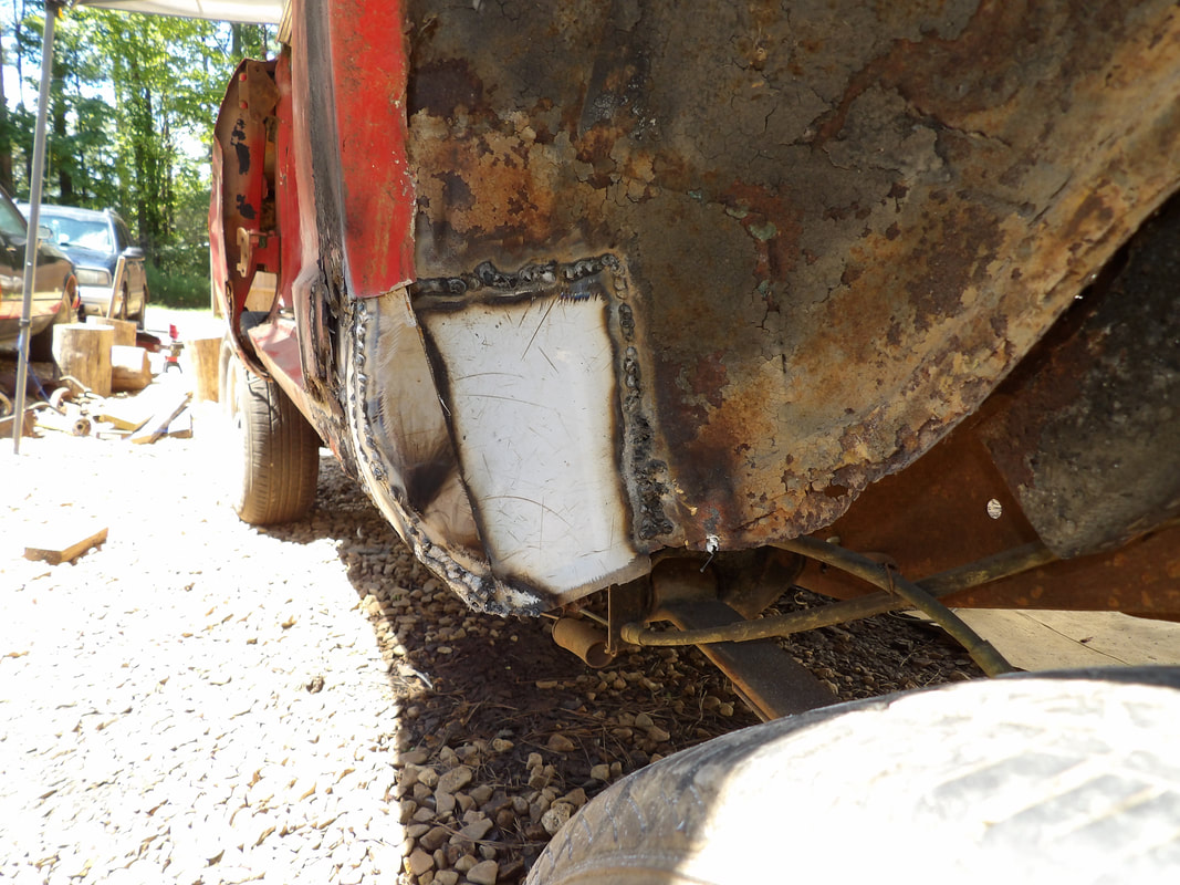 Small patch made on the tire well near the front of the quarter panel. Note the piece of meta welded in place on the fender lip to complete the lip going to the bottom of the quarter panel. With the left side quarter panel all patched up on the front side of the tire well, I moved on to the right side. Of course this side was just as jacked up and needed all the bondo cut out and areas prepped up in order to weld in the patch sheet metal. I also took a minute to patch up the inside of the tire well, having to do the same thing with the prep work of grinding the metal down to give me some bare metal to weld to. I only managed to patch up the front of the rear quarter panel on both sides since I was in the mindset of trying to finish up all of the interior patching. I would get to the rest of the patching of the quarters and even the fenders and other body areas when I got to the exclusive work on the body later on. 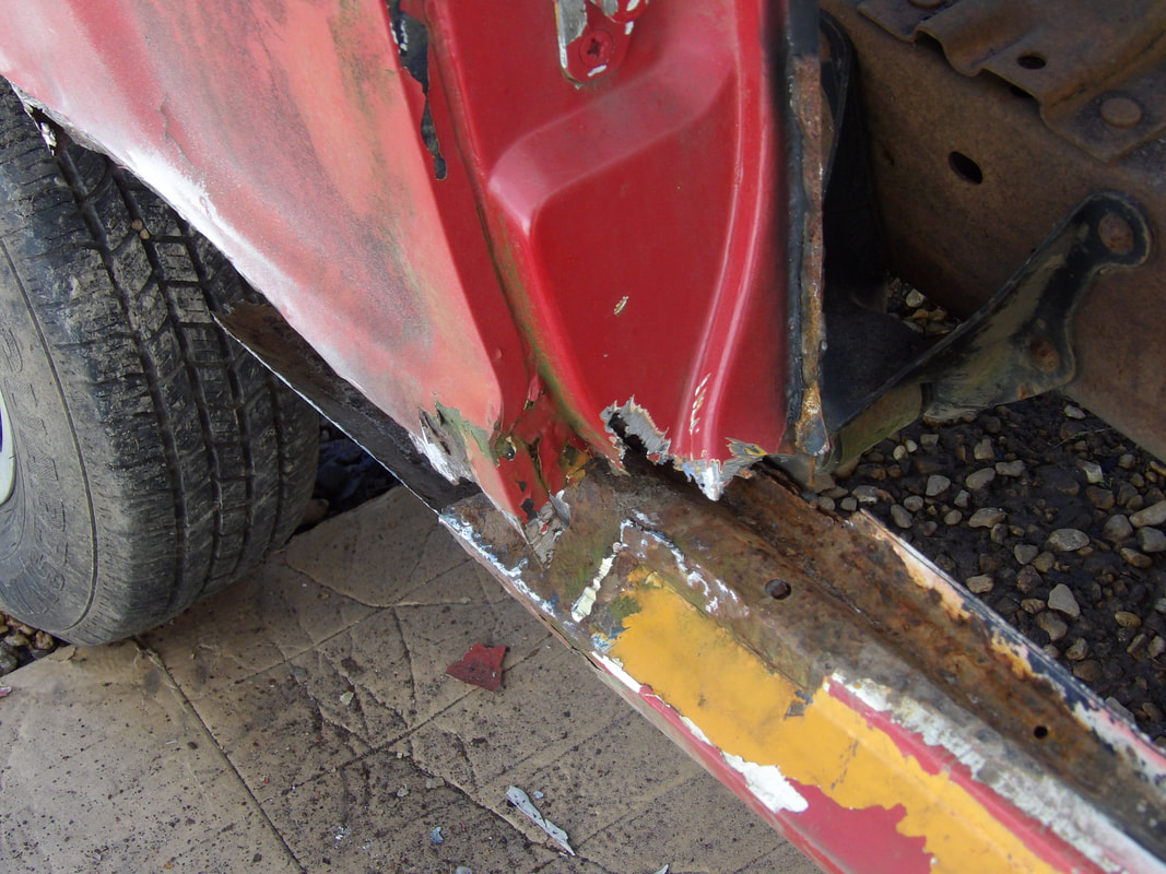 Rotted area of right side door jamb that is ground down in preparation to weld patch metal in place. 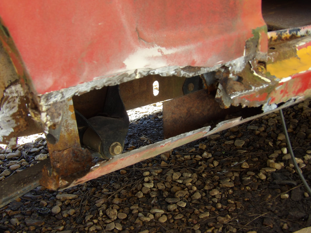 Front side of right quarter panel with rotted metal and bondo cut and ground away to leave a prepared surface for welding the patch metal in place. 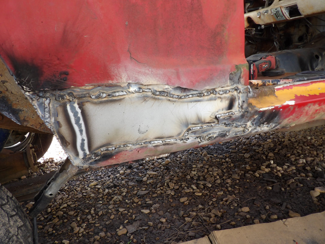 Patch sheet metal welded in the hole on the quarter panel. 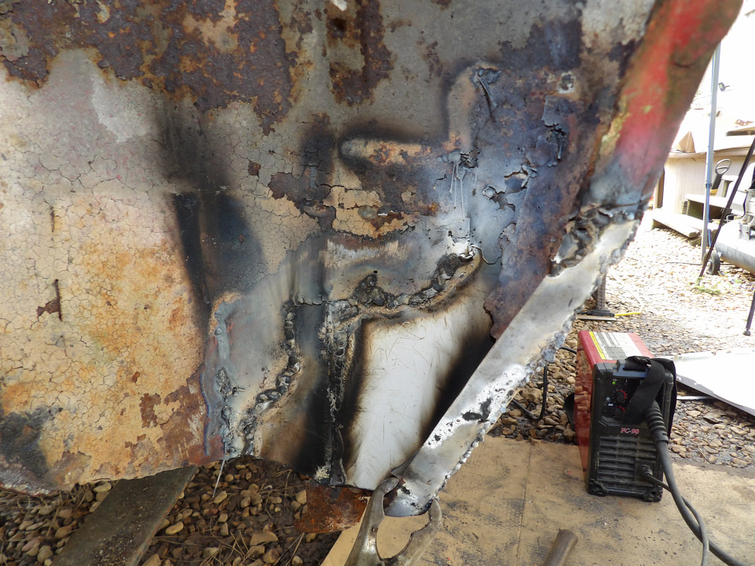 Tire well patch metal along with fender lip patch welded in place at the bottom of the tire well. With the patchwork done, I can now get back to the interior and getting the rest of the floor made. I still have to make support members that hold the bolts that would be used to complete the final set of body mounts, in the interior of the body, near the middle. We're at about the halfway point on the interior/floor patching. With my floor pans prepped and ready to go, I started off this session with the welding of the front seat floor pan. Once I got both ends welded in good I was able to do the final fitting of the intermediate floor pan. I started off with tack welds in random spots to get the pan where I wanted it to be before doing the longer welds to close the whole pan in. Unlike the left side intermediate floor pan that is an actual replacement floor pan, this piece of scrap sheet metal is thinner and by default, more flexible. 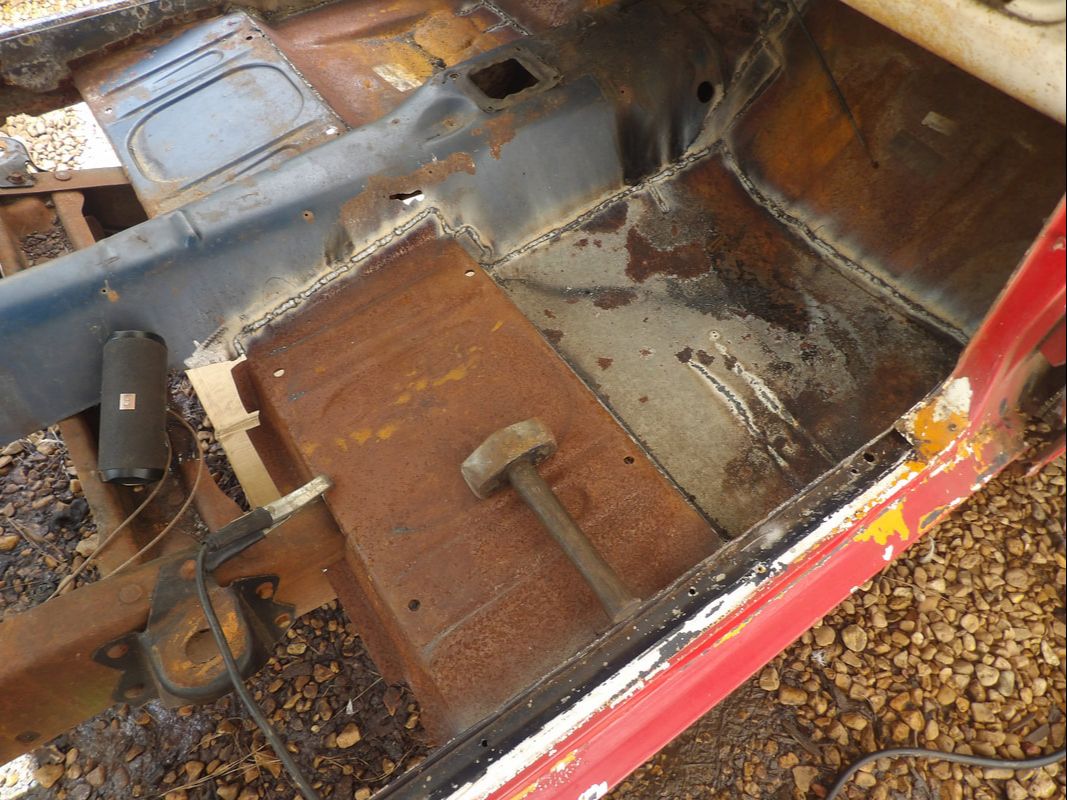 Shot of the front seat floor pan and intermediate floor pan welded in place. More on the flexibility in a moment. With the cuts of metal that I did, and the minor cuts at different points on the scrap piece, I was able to weld the entire piece in place almost seamlessly, with no need to add any extra pieces of metal to fill any gaps. On the outer front corner the metal wasn't perfectly ground down so the welds were a little shitty in comparison to the other areas so we ended up with more of the dreaded popcorn welds. Of course this problem is more prevalent with flux core welders but we have to work with what we have. 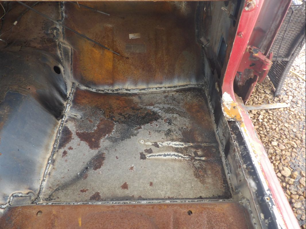 A shot of the intermediate floor pan made from the scrap piece of sheet metal showing the welds that were made without having to add any extra metal. Now about that flexibility. Because of the thin sheet metal, the intermediate floor pan has the issue of flexibility, with the pan acting in the same way a speaker cone acts when it resonates sound. If unchecked, this pan would vibrate excessively, making the interior of the car noisy, which is already going to be an "issue" with the engine and exhaust system. I had to come up with a crude solution to this problem. My solution was to cut a piece of flat stock iron and weld it across the middle of the floor pan from the driveshaft/transmission hump across to the inner rocker panel metal. I would then weld the flat stock to the underside of the sheet metal to attach said sheet metal to the flat stock. This would help keep the sheet metal from being able to flex like it did before. 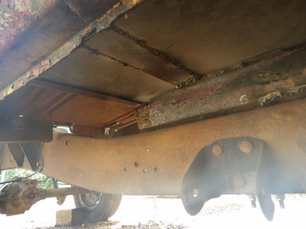 Piece of flat stock iron welded in place across the bottom of the sheet metal floor pan to help stiffen the pan so it won't flex. With this section of flooring done, our next move is going to be to weld in some angle iron across the backs of the front seat floor pans, going from the inner rocker panel metal across to the driveshaft humps. I was going to use a single piece of angle iron but was unable to find a piece long enough to span the gap across the body so I had to settle for a 4 ft piece of angle iron cut in half, with each half to be welded from the inner rocker panel across to and slightly under the remainder of the driveshaft hump. This will help in strengthening the front seat floor pans as well as add to the overall rigidity of the floors in the car. I also plan to add a couple more 2 ft pieces about a foot back from the front seat pans. These pieces of angle iron will sit over the last two body mounts with an added bolt welded to them to hold the body down at this central point on the floor. An appropriate name for this car would be the TruckStang, only because its a Mustang body on a truck frame. Anyway, when we left off we were "modifying" an extra front firewall to floor pan to "fit" in place on the section of floor between that pan and the front seat floor pan. I had to cut everything up to bend things in order to fit the pan as best as possible, which also involved some light tack welds to hold the pan where it needed to be so I can further manipulate the pan in order to fit as best as possible. Of course in the process I had to add pieces of metal in spots to fill little gaps and holes that were created in the process of making something fit that didn't belong in this application. 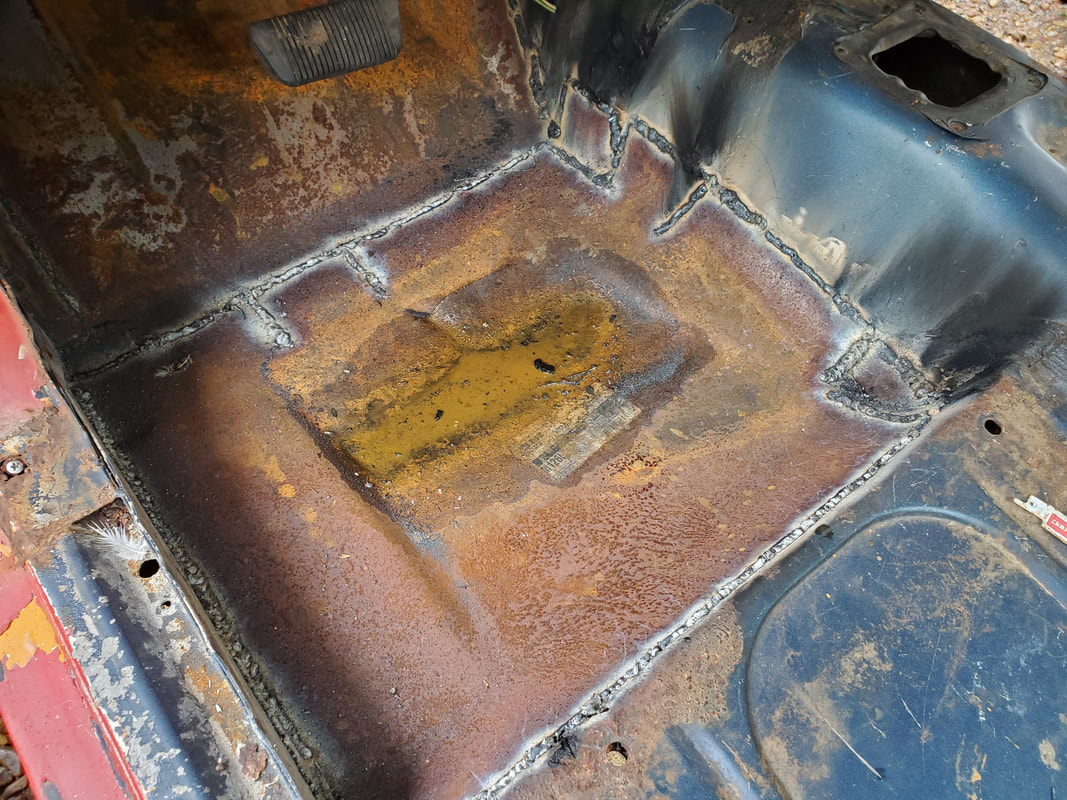 Intermediate floor pan after finishing the welding. Note the extra metal and welding on the inner rear corner to fill some gaps that were present after modifying the pan. Once the necessary tacks were made and the final fitment of the pan was satisfactory, I started making fuller welds in different spots to hold the pan in place. As stated before, I did have to cut little pieces of metal to fit in spots where there were larger gaps, such as the inner rear corner on the pan, or along the outer edge, on the inner rocker panel area. Once the pan was fully welded all around, I took a peek under the car to see if there was any possibility of maybe welding the rear subframe rail to the bottom of the floor pan for added strength. 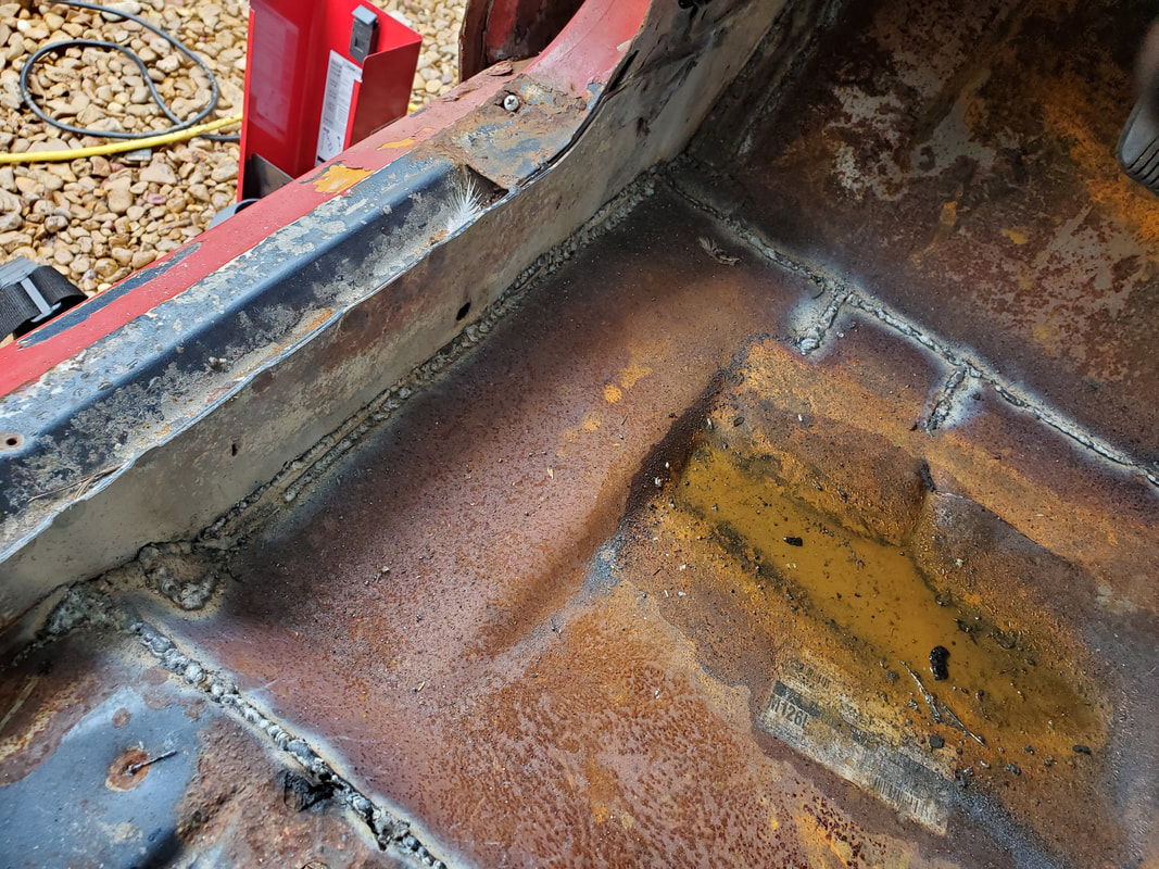 Outer edge of left intermediate floor pan showing the welds and the extra metal that had to be added along the inner rocker panel to fill the gaps. The front subframe at the absolute rear of the section was too rotted out to even be able to weld anything to the bottom of the floor pan. I would have to almost rebuild the subframe rail in order to accomplish this goal. Since none of this is load bearing the way it used to be, any future efforts at reinforcement will be geared more towards strengthening the mounting of the body to the truck frame. Our concern now is to ensure that the body will stay attached to the truck frame through thick and thin. With that, we moved on to the right side. 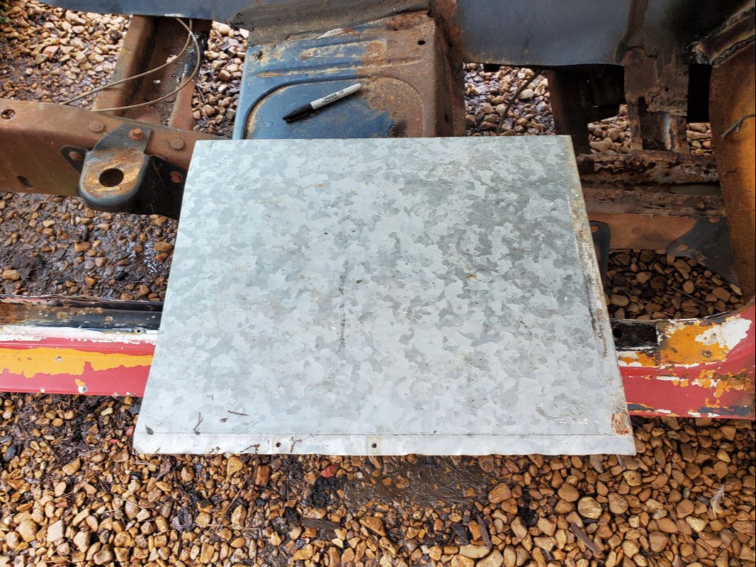 Scrap piece of sheet metal that will be used to make the intermediate front floor pan. I took a scrap piece of sheet metal and eyeballed how much I'd have to cut off in order to make the pan fit on the front floor section. At the same time I started grinding the front seat floor pan to prep it for welding. In the process, I found that this old pan was even more rotted than I was comfortable with. Since we did have a spare front seat floor pan, I decided to just use the new unit, cutting out the notch for the Ranger frame rail. I'll leave the rest of the floor pan that holds the extra metal where the seat mounts pass through for added strength. 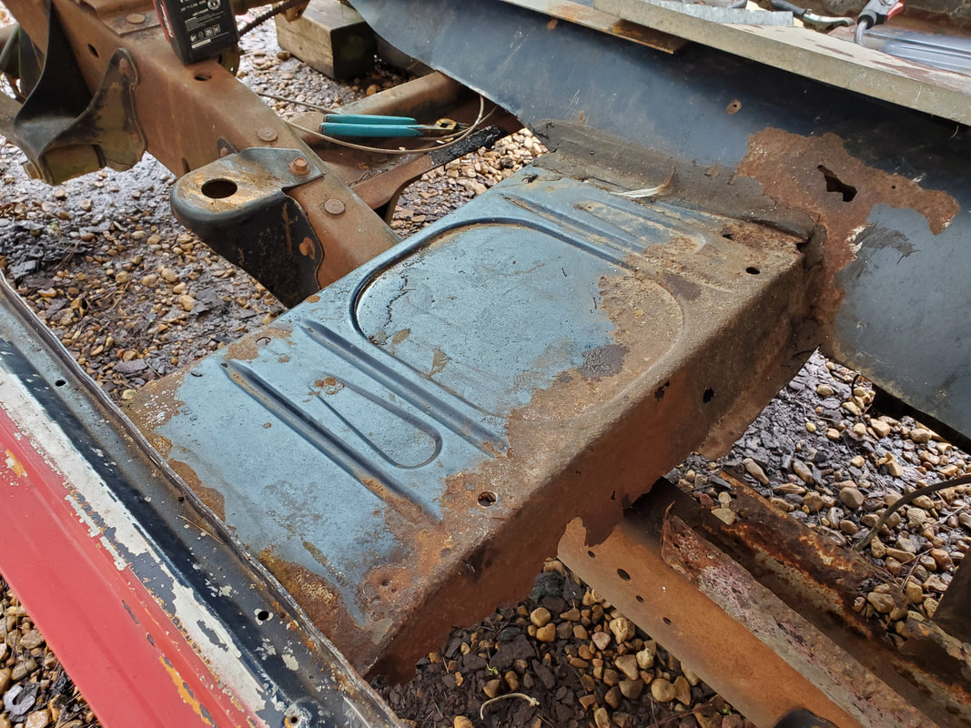 The old front seat floor pan. Why did I decide to save this pan again? I cut out the old floor pan, which was rather easy as there really wasn't much left of the pan on either side. After cutting out the floor pan I used the grinder to grind out the spot welded edges from the old pan and ground down the surfaces to bare metal to prepare it all for welding. I fitted the new pan in place after cutting out the Ranger frame notch, then staged the front floor pan in front of the seat pan as well. With that, we'll be ready to start welding everything in on the right side. 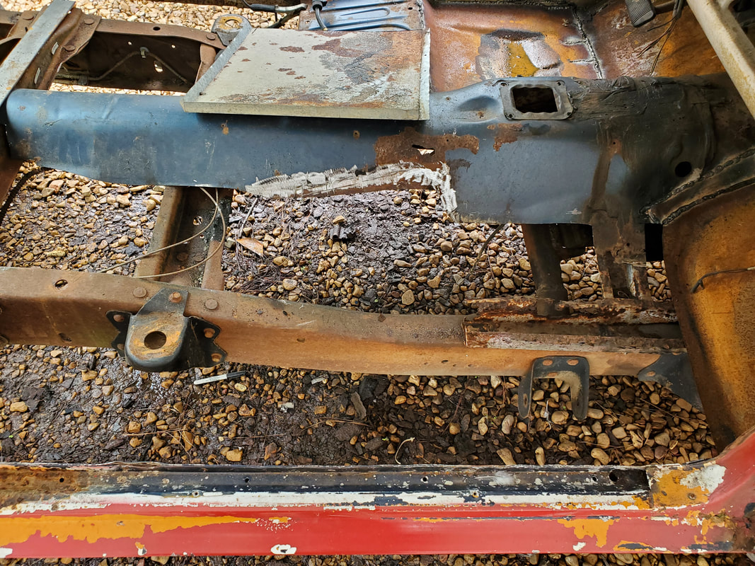 Front seat area after cutting out the old front seat floor pan and prepping the surfaces for welding. 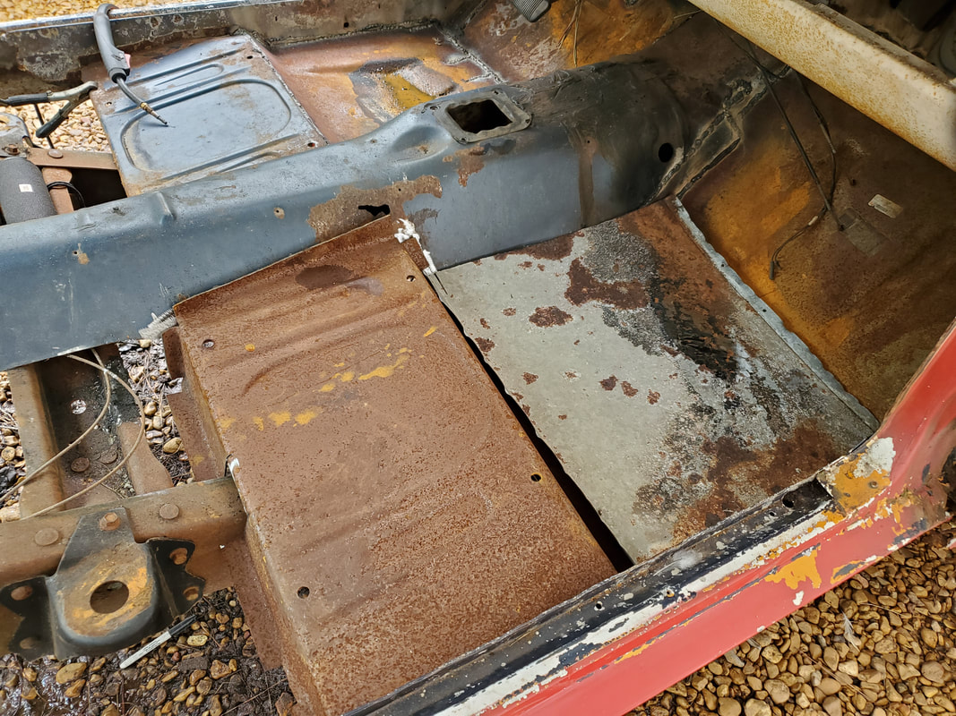 The new front seat floor pan after cutting out the truck frame notch. Pan is fitted in place along with the scrap sheet metal pan for the front floor pan to allow us to close in the front third of the interior floor. As on the left side, the right side subframe rail is rotted out too. We won't be able to weld the subframe to the floor pans so this isn't going to be worried about. We will continue to focus on getting the floors closed in and worry about adding extra metal later if any of the pans flex too much. I have a small concern that this mix/match of sheet metal on a unibody that was hacked up might have an issue with a resonation from the vibrating sheet metal, much like a speaker cone, causing excessive noise in the cab. I may have to weld some flat stock metal across the open sections of flooring to stiffen the floor pans to prevent this vibration effect later. We'll see. |
