|
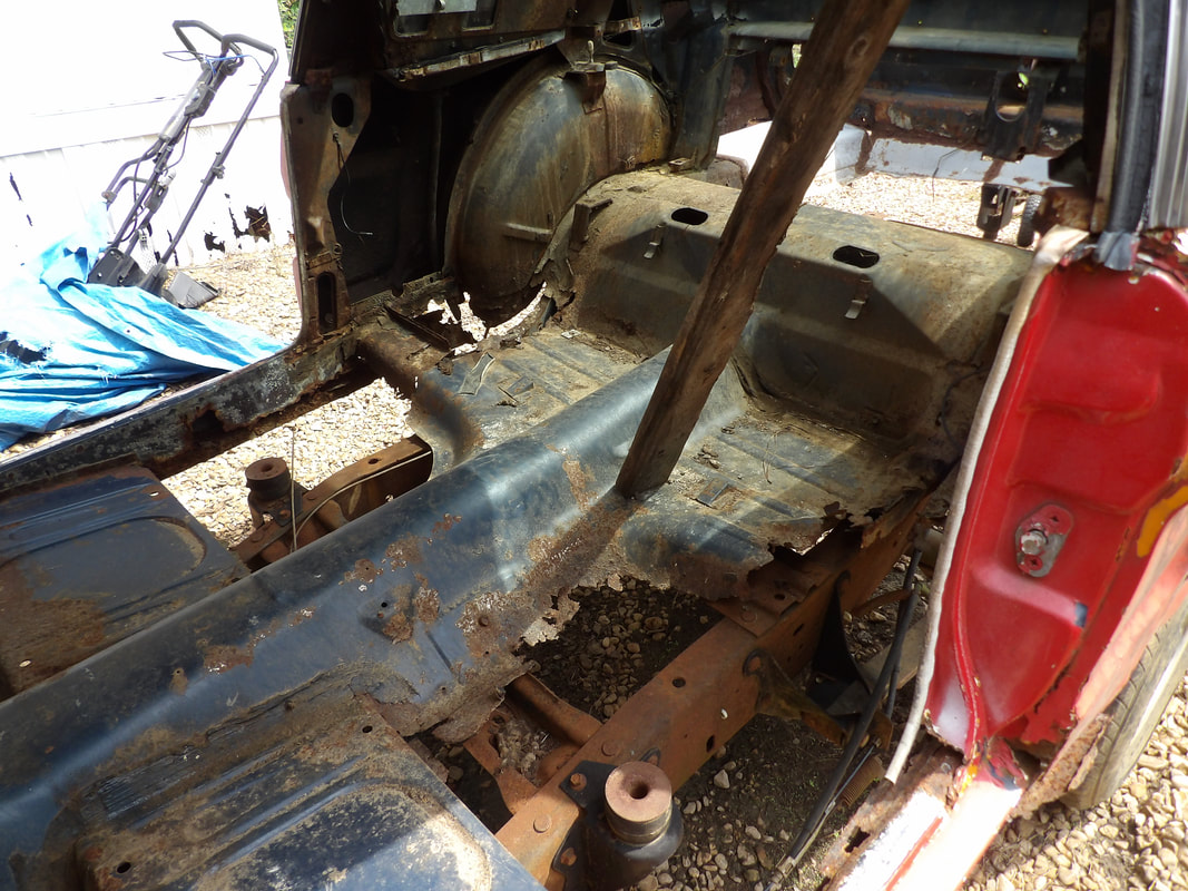
Today was pretty slow going on the floor patching on the Mustang. I had already trimmed down the floor panel that would be welded in place on the driver's side, along with cutting out all the metal around the old floor pan to accommodate the new metal. I started off with some light tacks in places to set the stage for the full welding of the panel. I started off at one of the corners, then moved to the opposite end then back again. Once the panel was where I needed it to be, I started doing fuller welds around the areas of the panel.
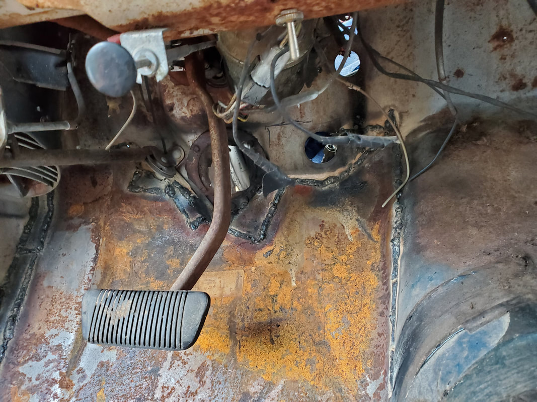
Front floor panel welded in place with all the seams around the contours of the area where the steering column and parking brake holes are located. Note the extra metal pieces that were added to fill the smaller gaps.
As figured from before, I had to add some extra metal around the edges in order to fill in larger gaps that were present due to things not perfectly lining up. This was fine as it was expected with this rusted out body. I had to cut smaller pieces of metal to fill in gaps around the cavities around the steering column hole and parking brake cable. A large long patch of metal was added on the outer edge of the panel where it attaches to the outer panel of the body where the hinges are located. Once this was all burned in, the front panel was sealed in, completing the two front floor panels of the flooring on the body. 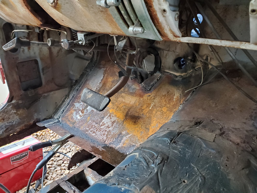
Outer edge of front floor pan welded up with extra metal to fill gap between it and the outer body member. Note the extra weld seams.
The next order of business was the intermediate flooring that would go between the new floor pans and the front seat panels. These two open sections are square in shape so they would require a very simple piece of metal to fix, or, I could use something that would've otherwise been unused, which is the extra front floor pan piece I had. Since this pan isn't made to go on the openings in question, I would have to manipulate the pan to fit the opening. This involved a few cuts made in multiple spots around the panel in order to flatten out the panel, as well as cutting out a few small pieces that would allow the panel's fitting in the opening. 
The extra front floor pan after making some cuts to help manipulate the panel to fit in the opening on the front floor section between the front most panel and the front seat panel.
Once all the hammering and pounding were done and the initial fitting was done, I wend ahead and did some tack welds along the front of the panel, connecting the panel to the back edge of the front floor pan to start things off. I will still have to do some extra cuts before I can fully fit the panel in place, and of course I'll have to add some pieces of metal to fill any gaps that are present after the panel is welded in on all four sides. 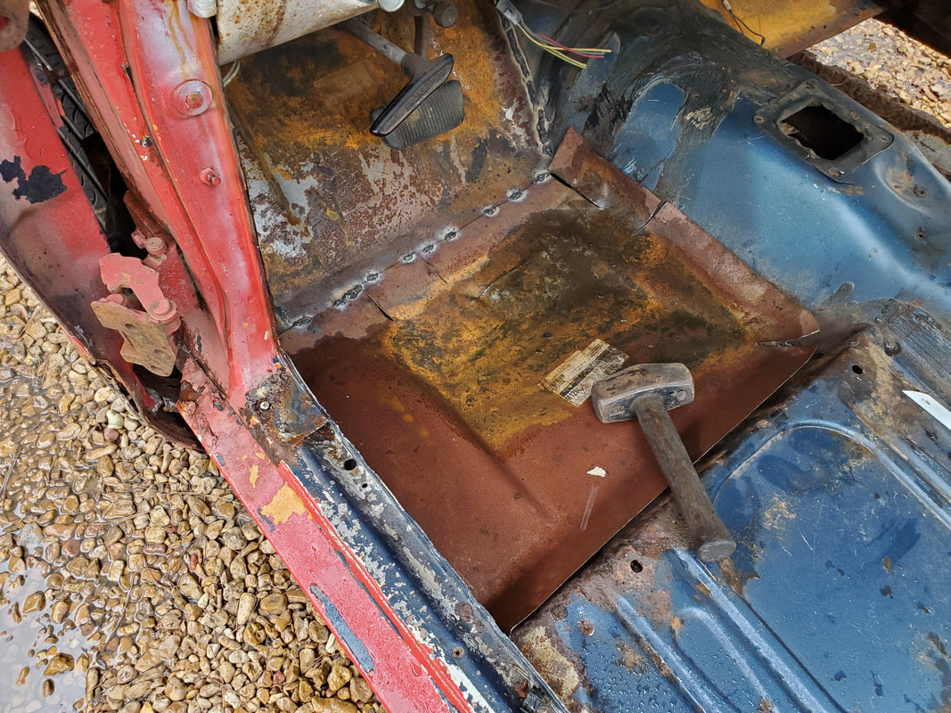
Tack welds made along the front of the "modified" floor pan to attach it to the rear of the front most floor pan.
This panel will of course be one of its kind as I don't have this same panel for use on the other side. It's just as well because trying to booger up another panel like this to fit is a last resort move. I do have an extra front seat pan that I could use, but this pan is special in its construction due to the reinforcement points that are added to the panel to aid in supporting the seat when its mounted. I could cut this panel up for the large square piece to fill the opening on the passenger side floor but I opted to just cut a piece of scrap sheet metal instead. This replacement floor pan may end up being used later on with the 69 Mustang, or even another car in the future, who knows. As it goes, we're working our way back on the floor patching. Once the floor panels are in at the front, we can start with the reinforcement for the last set of body mounts and the larger panels that I'll have to cut to fill the larger openings.
0 Comments
When I left off, I had run out of welding wire and ended up taking time to cut out some patch panels and do some other prep work around the interior in order to be ready to weld up everything once I replaced the welding wire. That area of operation is the right side rocker panel area inside the body. Metal needed to be welded in place in order to restore the rigidity of the rocker panel area and part of the quarter panel as well as provide an anchor point for some support members for supporting the new floor panels that I'll install later. I started off with the three pieces of patch metal that I cut prior to getting a fresh roll of welding wire.  Patch metal pieces welded in place around the inner rocker panel area on the right side to restore rigidity to the whole area. The patch metal that I welded in place is just a start. As I look further at what I need, I'll end up welding more patch metal into open areas to provide a nice solid surface that will help support all floor pan metal and support members that'll hold up said metal. The intent is to make sure that the interior will hold up good and not excessively flex where the body will make a lot of noise when moving down the road, as well as be safe enough that I won't have to worry about falling through the floor because part of the floor breaks free. The next order of business was to start prepping the floor pan on the driver's side for the NOS patch. Unlike the passenger side, there's a few more things I had to do to get the area ready, which will probably not make this patch up be straightforward. I had to remove the accelerator pedal, disconnect the parking brake cable, remove the old dimmer switch and even trim some of the excess metal from the patch panel since it extends up past the holes for the steering column and accelerator pedal. The cutting involves would also have it where the chances of having a perfect seamless edge will be pretty slim. 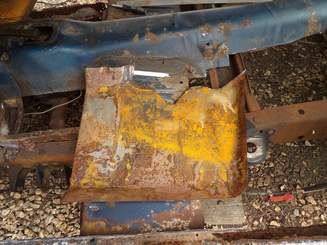 The NOS floor pan trimmed down to fit around the steering column and pedal holes so the extra work will not have to be done to accommodate the panel. Since this is not a high level restoration, paying attention to this level of detail is not necessary. We're going for function here more than aesthetics. I had to do multiple cuts around the old floor panel to take into account the idea that the old panel was attached to the subframe rails and other junctions around the body in this area. I had to grind and cut out a thick section of metal on the outer panel where the hinges are at so the area would be flat enough to not make for a distorted fit of the new panel. I also had to cut around the subframe to remove as much metal as possible to clean the area up. Even after trimming the new patch panel down, I had to cut the old panel to allow for some extra metal to remain to weld to. I already accepted the idea that I'll have to weld in some pieces of metal around the edges to fill in the inevitable gaps that will be present when I do start putting the patch in place. 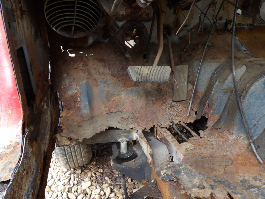 Left front floor area prior to cutting out old metal, note the level of rust/rot in the metal requiring repairs to make things whole again. Again, just like on the right side, I won't really have to worry about welding up the subframes as these will not be load bearing members that maintain the overall structural integrity of the unibody. I might have to still weld these points if it appears that the new floor patches may flex in a way to resonate like a diaphragm with the vibrations of the engine and rolling down the road. Of course this will mean I'll have to source plenty of welding wire to be sure to be able to do all the welds that I'll have to do with large and small pieces of metal. Again, this floor will look like a patchwork quilt when its all said and done with all the different sizes and shapes of metal in place. 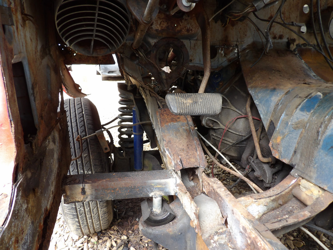 Left front floor to firewall area cut out in preparation for the new patch panel. Once I get the floor panel welded in I'll start looking at what metal I can weld in on the left side rocker panel area so I can get that area reinforced like the right side. I still have to source a long piece of angle iron so I can get that last set of body mounts addressed. In the meantime besides the rocker panel areas, I will also start looking at cutting and welding patches for the front floor area between the front seat mount panels and the new panels I welded in. Little by little I'll get the floors closed in. The time has finally come where the progress has brought us to the interior of the Mustang body. The body is mounted to the Ranger frame with the exception of the last set of mounts in the cab area so now the next order of business is the patching of the floors. Between replacing the rusted out sections of floor and installing new sheet metal and support metal in the areas where old metal was cut out during the mounting of the body to the truck frame. I already have some patch commercially made patch panels that I would weld in place. I started off with the front right floor pan that attaches to the firewall. 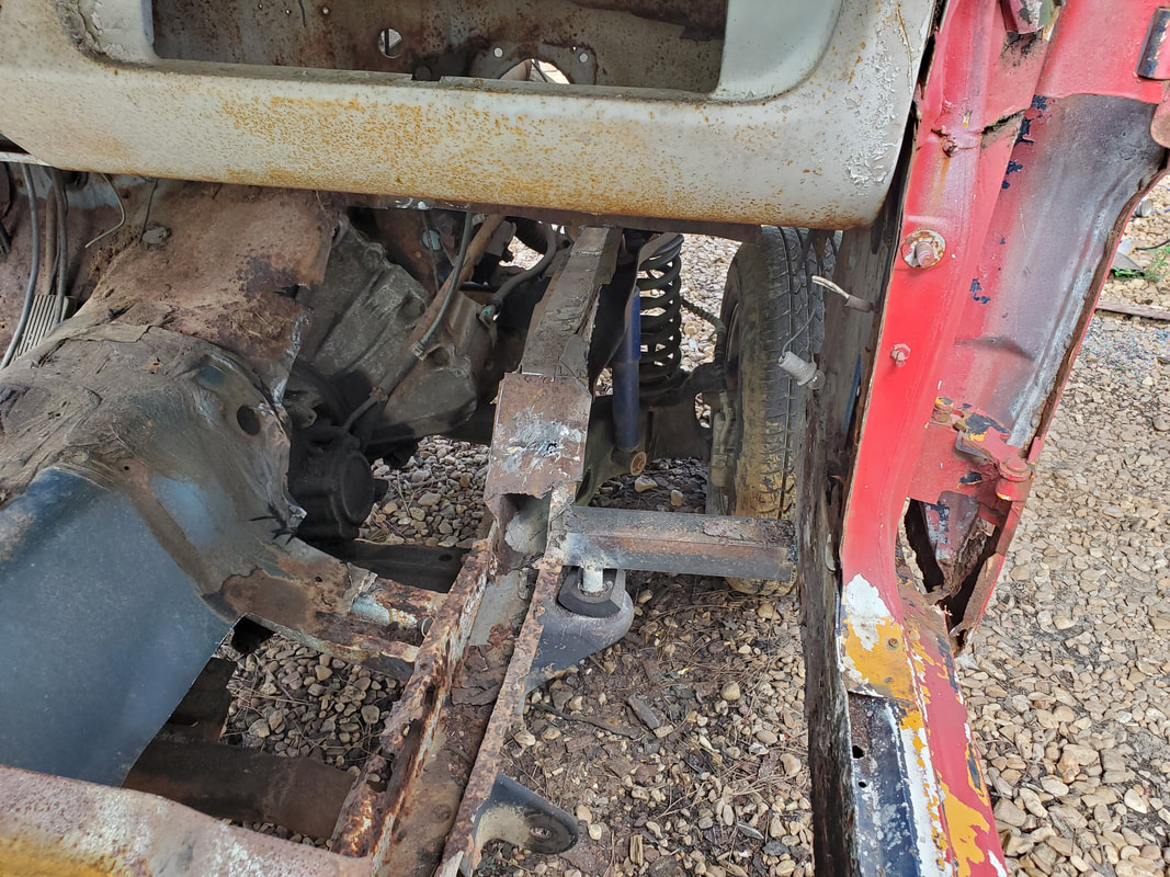 Old floor pan metal cut out in preparation to weld in the stock floor pan in this area where it connects to the firewall. Note the old front subframe rail where the metal attached. Since these subframes are no longer load bearing structural support, there's no need to weld to these metal members. After cutting out the rusted metal on the right front floor pan to open the area up for the stock floor panel, I prepped the area for welding and started burning small tacks around the top of the panel, then worked my way around the left of the panel at the transmission hump. I moved to the right side of the panel, having to add some metal to fill some larger gaps between the panel and the side wall of the body. I ran out of welding wire just a few inches shy of finishing the complete welding of the panel. 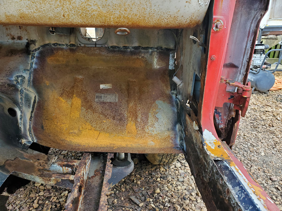 Stock floor pan welded in place on the right side, going up to the firewall. Note the extra metal that was welded in place on either side. From here I couldn't do any more welding since I was out of welding wire, so I moved on to prepping some other areas of the interior for future patching. The inner rocker panel area on both sides were rusted out badly and will need large patches of flat metal to cover the areas and provide solid surfaces to weld other braces and supports for the greater sections of floor pans. I ground rusty metal down to bare clean metal and cut out the extremely rusty metal that is unable to be welded on. I prepped up the area on the right side at the rear of the rocker panel area where it would allow me to reconnect the rocker panel to the door jamb and rear tire well. I also took time to cut out large sections of the rear floor area around where the Ranger frame raises up past the level of the old Mustang floor pans. I'll weld in new sheet metal and supports at a higher level that will put the new floors above the Ranger frame, covering everything up. 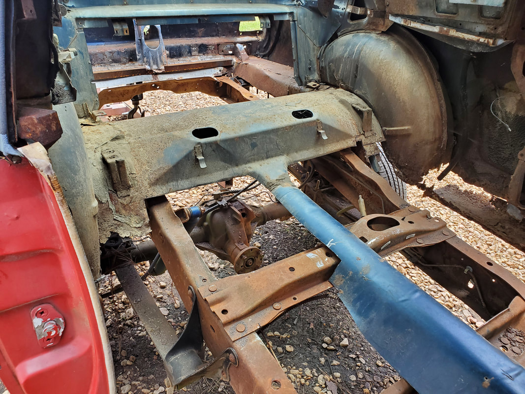 Rear floor sections cut out to provide edges that are at the right level to put the new floor sheet metal at a higher point than the Ranger frame rails. After prepping the rocker panel area on the right side, I took some of my metal stock and cut some patch pieces that will fit over the areas that I plan on patching and reconnecting. These patches may be duplicated for the left side as well but since I couldn't weld anymore in this session, I used my time making patch metal so on the next session I can go straight to welding the patches in place to make some quick progress in getting the interior structure completed.  Patch pieces of metal cut out and prepped for welding in place along the right rocker panel area in order to connect the metal to restore support and rigidity of the rocker panel, door jamb and rear tire well metal. At this point, I'll be using all kinds of scrap metal to try and close in the floors of the body. I already know when this phase of the project is done, the whole floor is going to look like a patchwork of miscellaneous pieces of metal. Only difference will be the structural members that I'll have to add underneath the floor pieces to aid in support of the sheet metal. I'll have to take into account supporting that last set of body mounts, as well as the seat mount panels. I did have a replacement seat mount floor pan, but refrained from using it due to the idea that I had to cut up quite a bit of metal from the old pan to get it where the edges of the pan will be at the right level for the new floor pans to connect nicely.
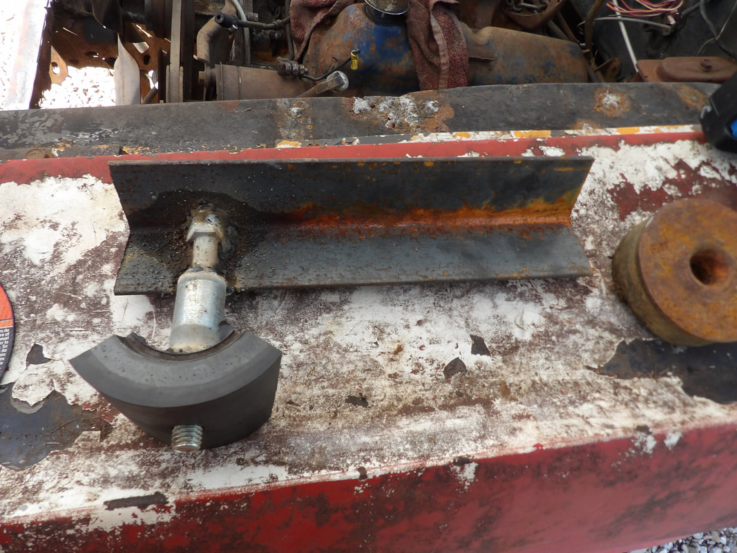
With the 65 Mustang's body mounted to the Ranger truck frame and the engine crane pulled away for the last time, I can start moving to the cab to start work on patching up the cut up floor area. In the meantime, I also have a couple sets of intermediate body mounts I have to address. Both of these are not going to be handled the same way as the front and rear sets of body mounts, as one set is inside the cab and with its position relative to the floors, would not allow me to use any kind of cushioning rubber to go between the mount and the truck frame. This will have me installing a piece of angle iron that will hold a couple bolts which will just be secured to the Ranger frame body mounts. Worst case will be a very thin piece of radiator hose being used as a crude cushion between the members. The other set of mounts is just under the firewall on the outside of the body. I will be able to use some of the thicker rubber I used on the other mounts, but the whole mounting assembly will have to be done in place, since the body is already mounted. I can't assemble the mount member then add the rubber and lower the body down. This is where we begin on this leg of the journey.
Body mount bracket assembly welded up and ready for installation.
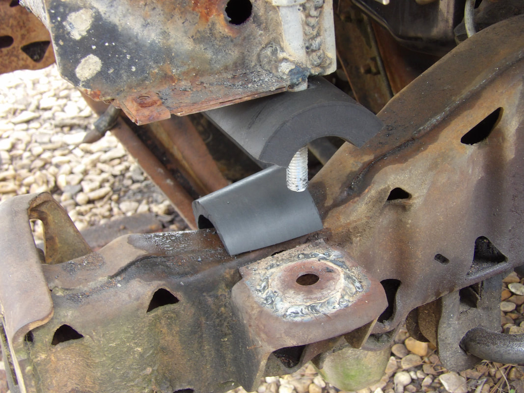
The way I came up with to fabricate a mounting assembly was to take some more angle iron I had and weld another bolt to the piece. After test fitting to see how I would be able to apply the thick rubber, I ended up digging up a large 1/2" bushing and a washer with which to weld to the stud of the bolt. This provided an anchor point for the rubber to sit on, extended down low enough so when the member is in place, it will press the rubber down onto the Ranger frame body mount, and be secured with a nut and washer. I would then weld this angle iron member, with the rubber in place, to the rear of the front subframe and the structural member where the door hinges are located. 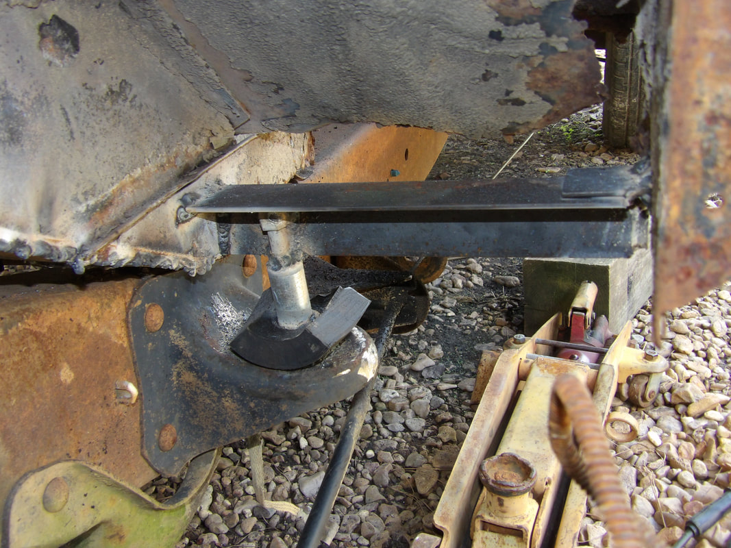
Left side outer intermediate body mount bracket assembly installed with rubber bushing cushion.
Because of alignment issues, I had to use a floor jack to jack the outer end of the angle iron up enough to allow it to reach the structural member to get a large amount of welding area in place. Once both ends were welded in place, to no risk to the rubber piece, I secured the bolt stud with a nut and washer to write off that body mount on the left side. I moved on to the right side, duplicating everything there and getting the member welded in place and secured with a nut and washer. 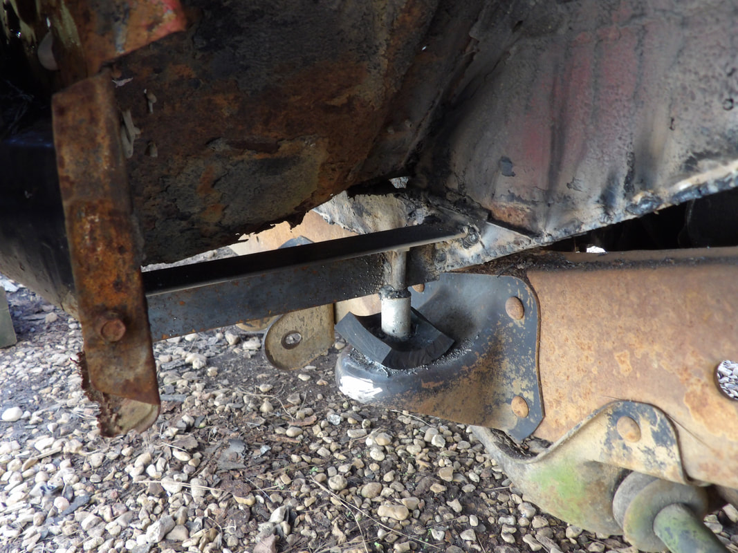
Right side outer intermediate body mount bracket assembly welded in place with rubber cushion installed.
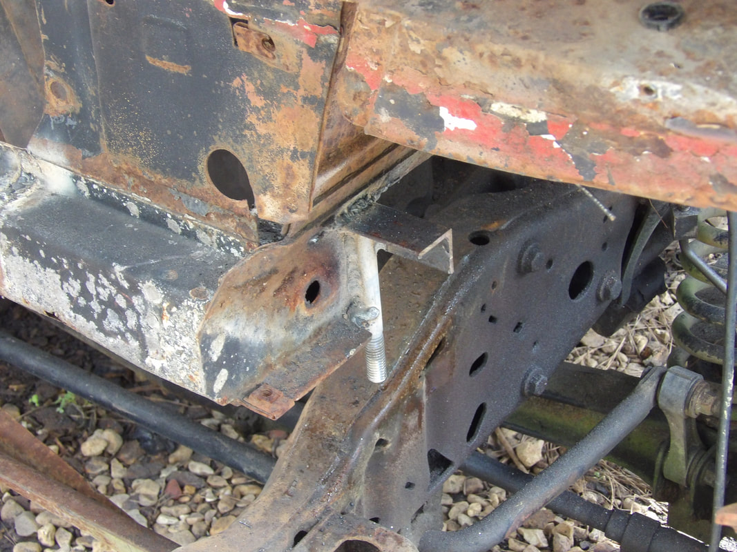
With the outer intermediate body mounts taken care of, I moved on to the mounts in the cab area. The Ranger frame body mounts still had the rubber bushings installed with the remnants of the bolts that held them to the body. I had to cut all this out, first using a wood blade on the reciprocating saw to chew up the rubber and expose the metal core. I switched to a metal cutting blade to cut through the metal bushing at the core of the rubber bushing piece, removing both bushings from the body mounts in the cab area. 
Right side body mount bushing cut out using saw.
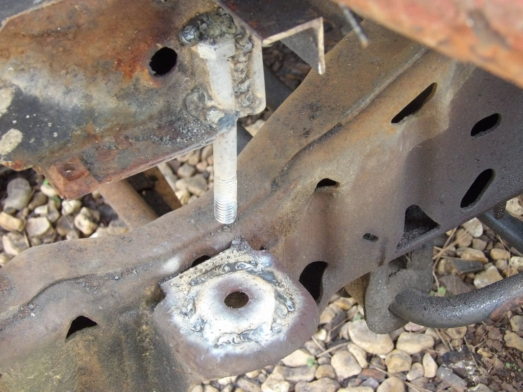
Left side body mount bushing cut out from intermediate mount in cab area.
With the outer mounts done, I can start work with patching the floor in the areas I'll be able to get with the current stock of metal I have. I have to source another piece of angle iron to use for setting up the body mounts in the cab area, which will have me placing the angle iron across from one rocker panel to the other and going through the driveshaft hump. Since the driveshaft won't be passing through this area due to the height of the hump relative to the driveshaft, this move will be permitted. I will also have to do some minor cutting of rusted sections of floor pan to get to solid metal so I'll have good surfaces to weld to when I start installing patch metal. I also need to weld in some flat stock on the insides of the rocker panel areas to provide some solid surfaces for welding the body mount angle iron and the floor patch metal as well. Once the floors are all closed in we can then move to actually reassembling the Mustang's body. I will have to do some crude patching to the rusted out body panels like the fenders and quarters, but once this is done we can move forward getting the overall body reassembled before moving on to fitting out the interior and getting all the systems hooked up and online on the car.
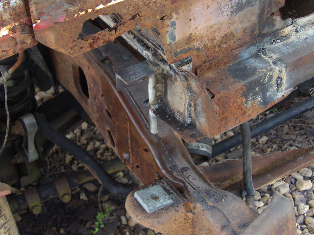
After all the work that was done, we're finally coming to the point where we can technically say the mounting of the Mustang's body to the Ranger truck frame is complete. The front mounts are secured completely, so now we have to get the rear most mounts taken care of. I had to figure out a way to do this as all we have to work with in the rear is the sheet metal that makes up the old trunk floor and the rear subframes, which all this sheet metal is attached to. The first thing I came up with was taking a piece of angle iron from the supply and weld a couple long 1/2" bolts to the iron on the inside of the angle. I had to line up and drill a couple holes from the mounting points on the Ranger frame going into the rear section of sheet metal on the truck floor, which is also connected to the taillight panel. Once this was done, I could insert the bolt studs on the angle iron through the holes in the trunk floor panel and into the holes on the truck frame.  The angle iron body mount member with bolts welded in place, ready for test fitting. 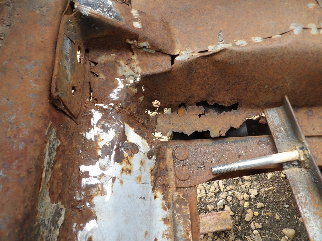 Hard to see, but another hole is drilled through the rear of the trunk panel down to the Ranger frame mounting point. Note the angle iron piece with bolt bolted to it. 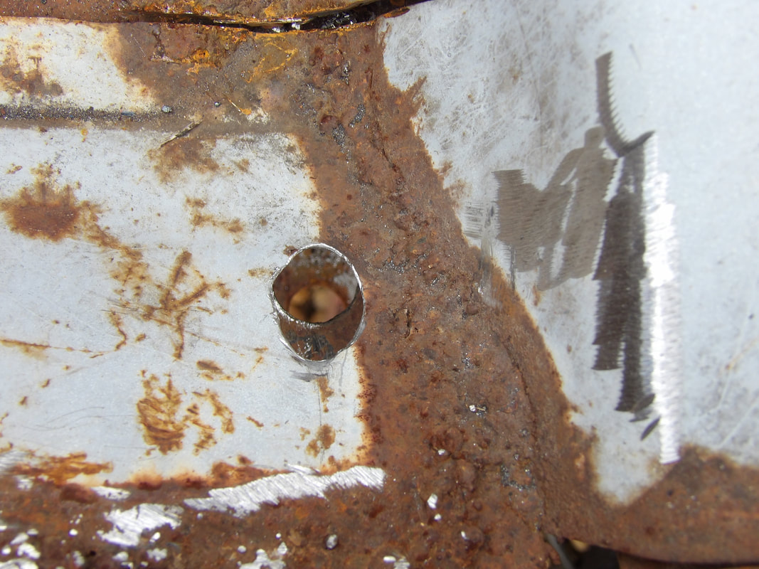 Hole on right side of rear trunk panel drilled through to line up with the hole on the rear of the Ranger frame rail. Once everything was lined up with the angle iron bolts and the holes on the trunk panel and Ranger frame, I took a couple pieces of rubber and some washers to test fit them. Once that was done, I marked the spots on either side I wanted the angle iron to go and removed everything except the angle iron so I can start welding. 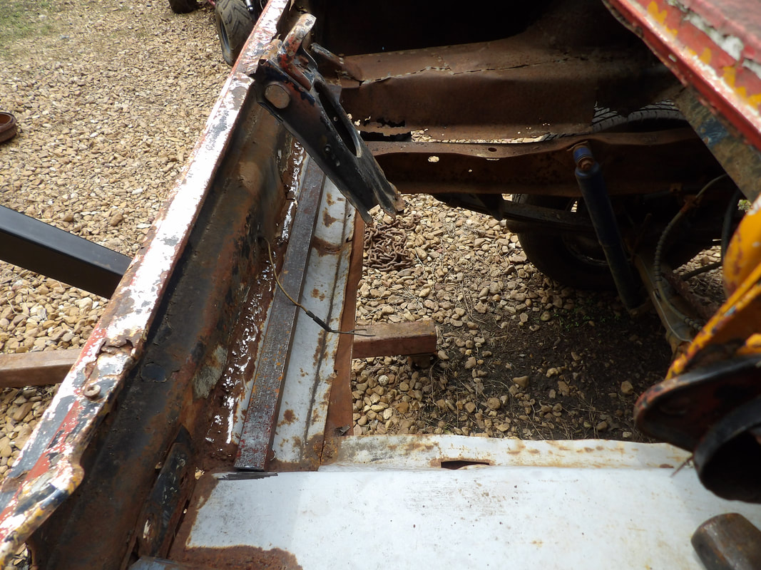 Angle iron body mount assembly being test fitted in rear of trunk floor area. Note how trunk latch member had to be lifted up to open the area for fitting and welding. 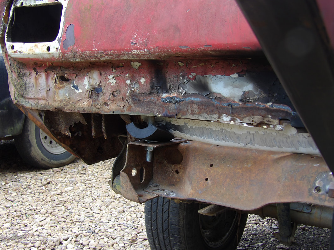 Rubber inserted on left side bolt stud during test fitting of angle iron body mount assembly. 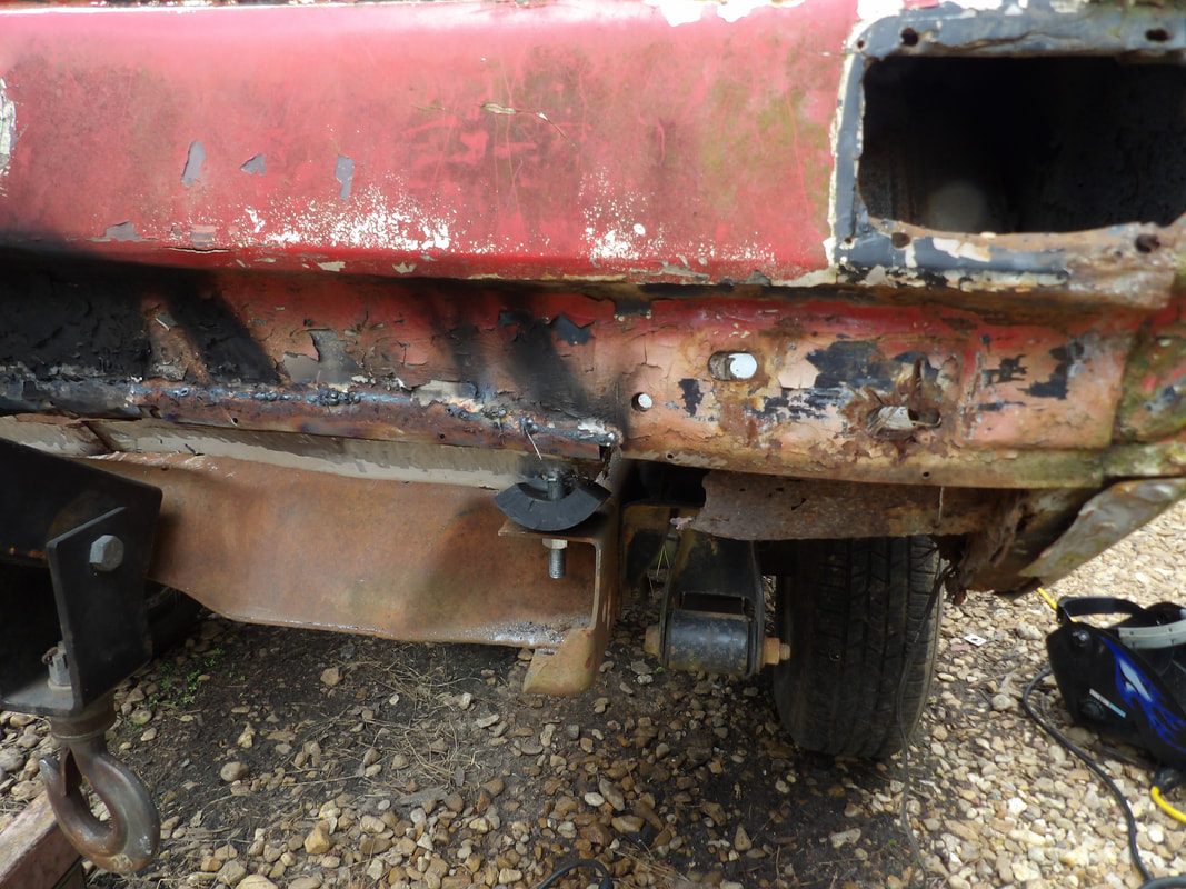 Rubber installed on right side bolt stud during test fit of angle iron body mount. Because of how the angle iron sat on the back of the trunk panel, I ended up with a gap along the back. Because of this, I had to cut some narrow pieces of iron to weld between the angle iron and the back of the trunk floor where the taillight panel meets. I had to pull up the member that held the trunk latch point to give clearance for the metal as I welded. I'll end up trimming and welding that piece back later. Once the metal was welded in completely, I was able to put the rubber over the studs protruding from the trunk panel. Before lowering the body down on to the truck frame I took a couple thinner pieces of rubber and sat them on the top of the Ranger frame where the Mustang's old shock tower metal made contact. I lowered the body down, sandwiching the rubber between the shock towers and the top of the Ranger frame as well as placing the bolt studs through the holes on the frame, with the thicker rubber in place. Washers and nuts were placed on the studs and tightened down, securing the rear of the body to the Ranger frame completely in the rear. 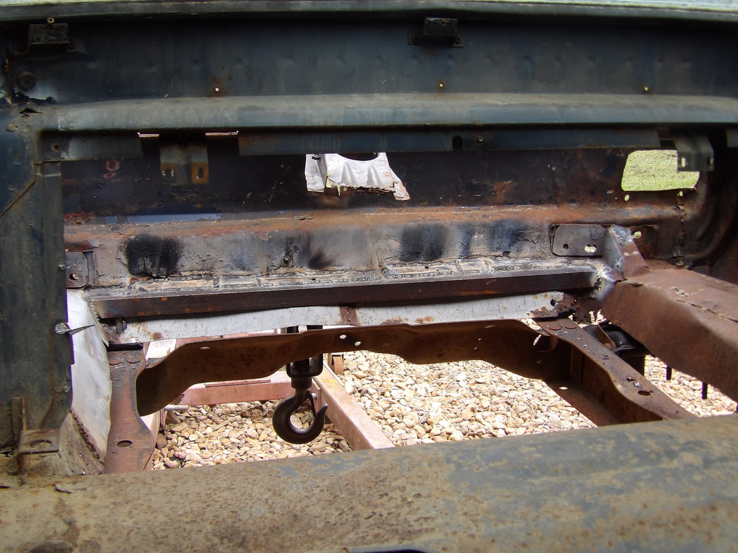 Angle iron/bolt arrangement welded in place at back of trunk, using extra metal to fill the gaps between the angle iron and the taillight panel. 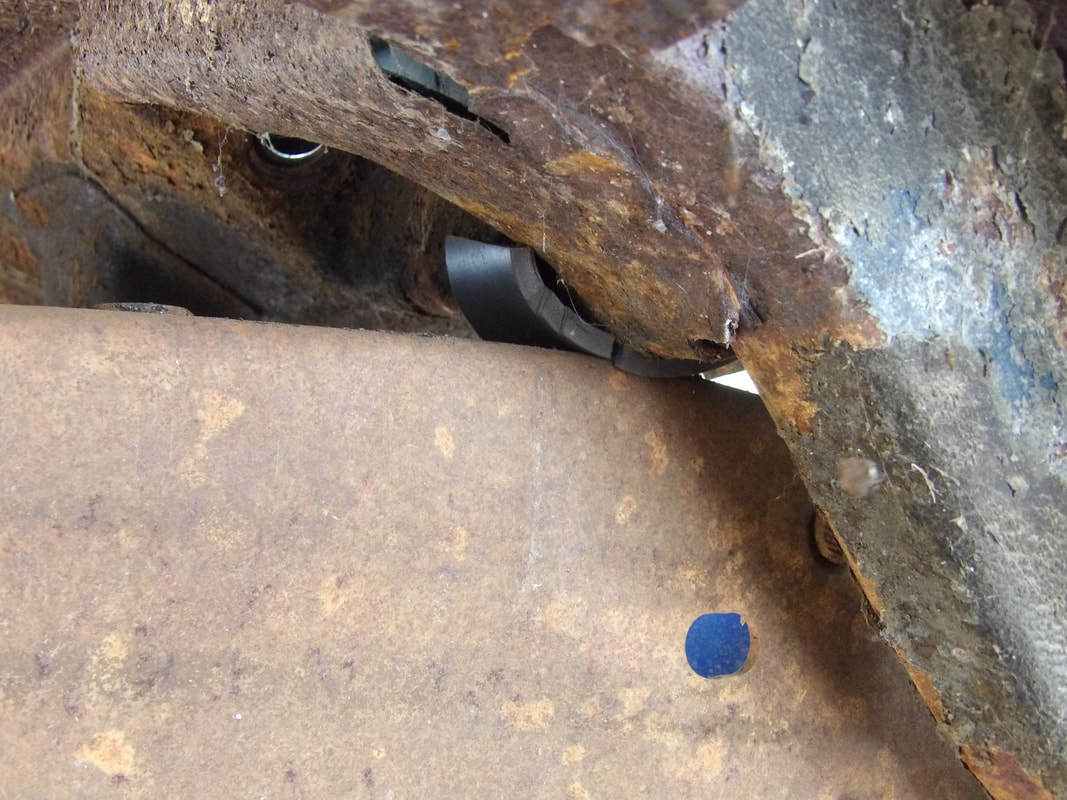 Thinner rubber piece sandwiched between Mustang's old shock tower outer surface and the top of the Ranger frame to cushion that contact point in the rear of the body. This is done on both sides. Even though there are two more sets of body mounts on the Ranger frame at intermediate points, I'm not going to count these towards the overall mounting on the body since we only needed to get the front and rear fully secured to consider the body down. The set of mounts in the cab area are at a position that wouldn't allow us to install bushings on the bolts that would be installed, meaning that this mounting point will be more of a metal on metal direct bolting of the body to the frame in the middle for some more solid mounting. The other set of mounts, just under the firewall, will be able to have a rubber cushioned mounting arrangement, but everything will have to be assembled in place, since the body is already mounted to the frame. We'll get to that on the next go around. With the front of the Mustang body secured to the front of the Ranger frame, I moved the crane to the rear and jacked up the body to get the drums and board out of the way. Once I lowered the body down, I was able to get a first glimpse of where the body would be making contact with the Ranger frame. I found the first contact point was on the rear seat area just forward of the rear shock towers and right next to the rear subframes. I started off with cutting out the metal from these areas to allow for clearance of the Ranger frame rails and the right shock. It helped out a little bit on allowing the rear of the body to come down lower, but there were plenty of other contact points I had to address. 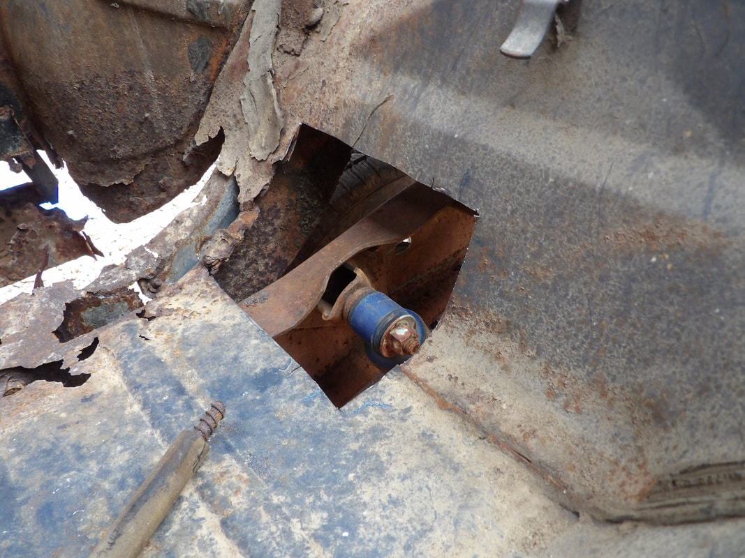 Section of rear floor cut out around Ranger shock and frame rail to allow for better clearance. 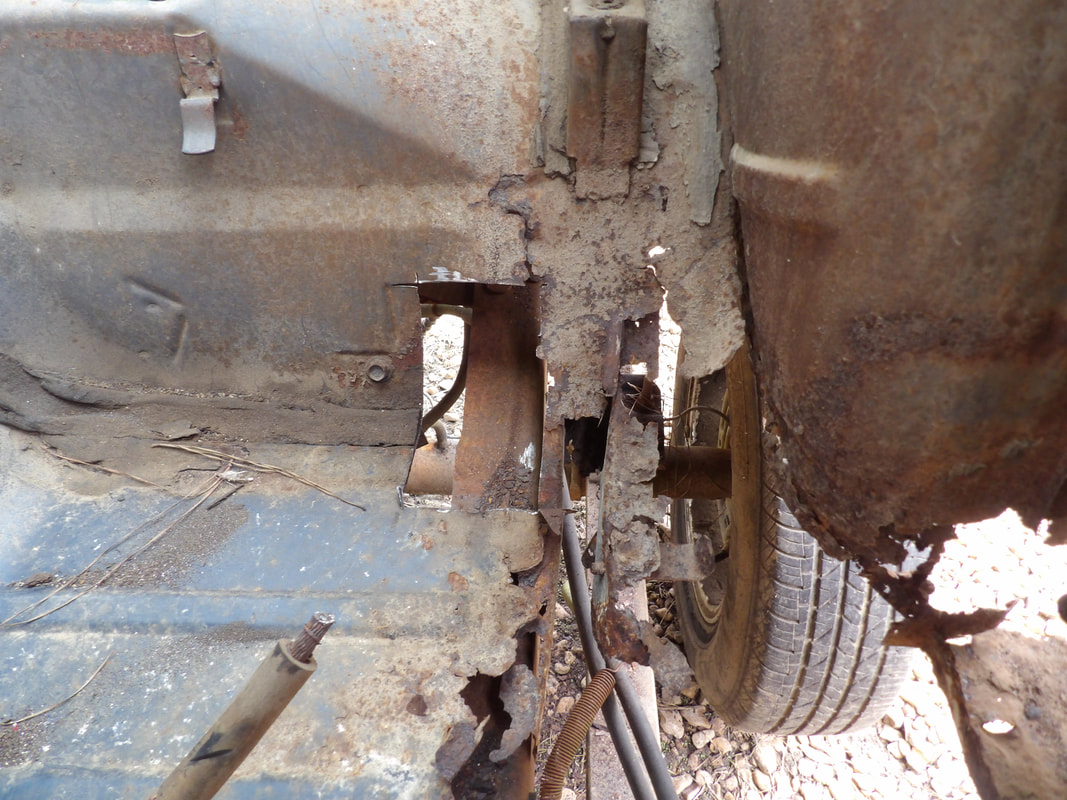 Section of left Ranger frame rail exposed after cutting out section of floor pan. Other contact points that I had to address were in the rear floor section behind the front seat mounting area. There's a couple crossmembers on the Ranger frame that ride higher than the Mustang body floor pans. I had to whittle away a lot of metal to open the area up around the crossmembers. Cutting this metal allowed the Mustang body to come down lower, but there was still room for improvement . 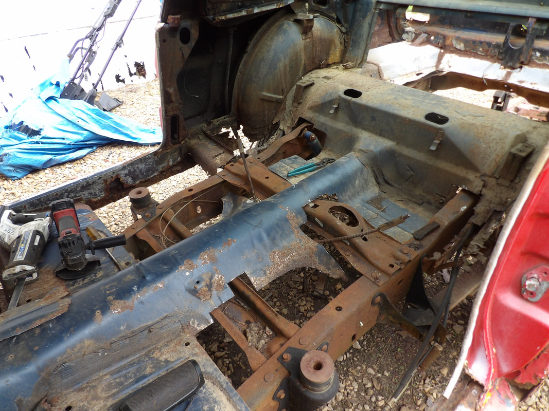 Angle from left side showing the metal that was cut away from the floor pans to allow clearance of the Ranger frame crossmembers so the body can be lowered more. 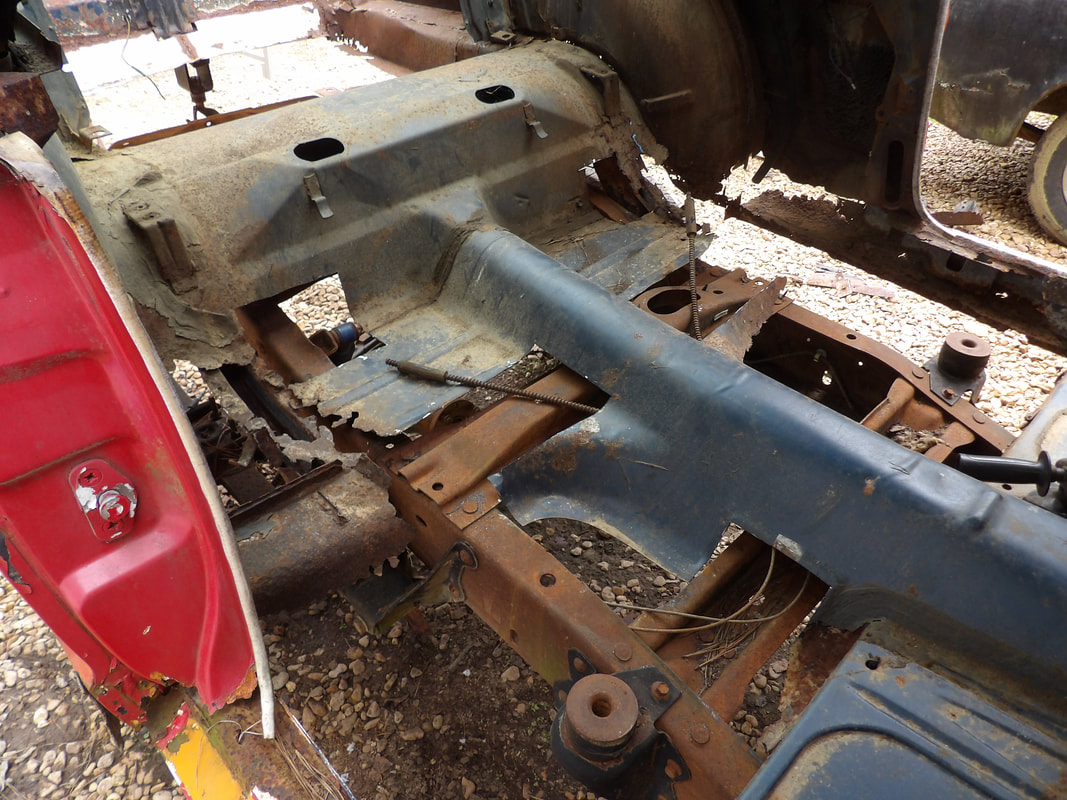 Another view from the right side giving a better shot of the right side showing the cut out floor pan for clearance of the Ranger frame crossmembers. I also had to do some cutting in the trunk area to aid in giving more clearance so the Mustang body can sit lower on the truck frame. The sections of trunk floor around the gas tank hole made contact with the rear most sections of Ranger frame rail so I did a little trimming here as well. I cut out some of the trunk floor at the front of the trunk even though it wasn't making contact with the truck frame due to the fact that this metal was rusted out enough that I wouldn't have been able to weld any new sheet metal to these surfaces. I cut out the rusted metal to make the new edge be of more solid sheet metal that I will be able to weld to. This little action allowed the Mustang body to come down even lower on the frame. 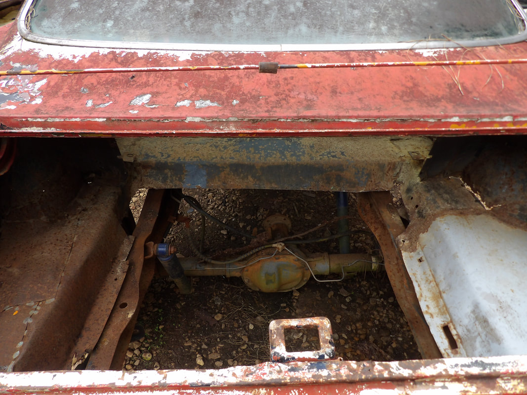 The trunk area after cutting out the interfering metal that was making contact with the rear sections of frame rails. Another area that I found was making minimal contact but enough to be a problem was on the rear of the front seat mounting panels. The truck frame rails were making contact at the rears of these panels where I had to cut out a small piece of metal from each panel to allow for more clearance. Once that was done, I was able to gain some more lowering. 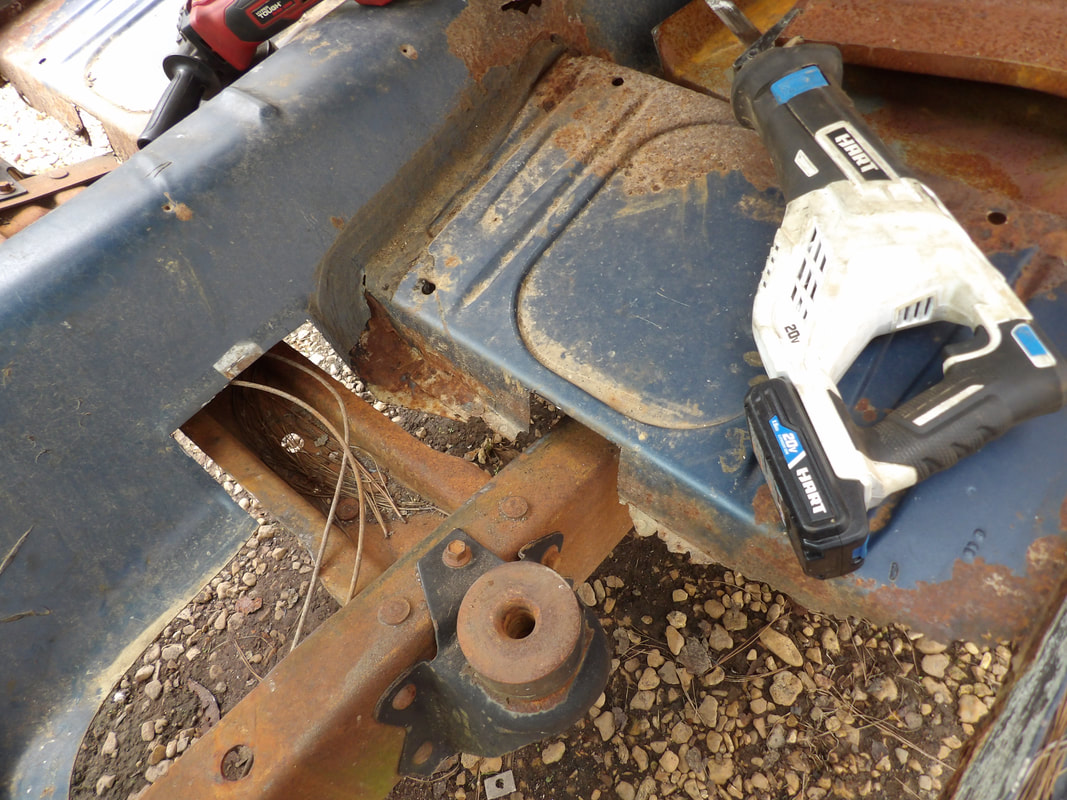 Right front seat with notch cut out to clear the truck frame. Note the other cuts in the floor pan around the driveshaft hump to clear the crossmember. 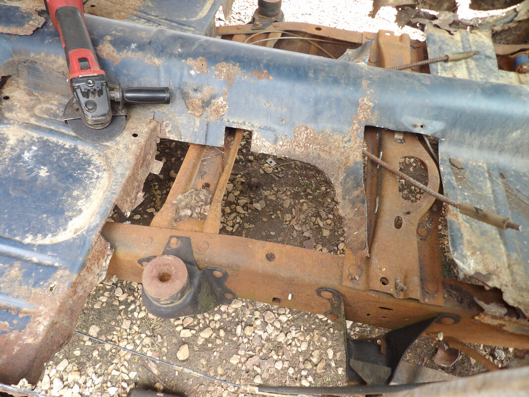 Left front seat with notch cut out for clearance. Note the other cuts around the crossmembers to aid in clearance. After all the cutting that was made to allow the body to clear the truck frame good enough to come down, I was able to get the body to a point where it was level. The body was good front and back, not to high on either end. I used a level to confirm this. Even though its not 100% accurate due to variations in the ground and even the body but it was good enough and my eyes were satisfied to say that the body was leveled. At this point I wasn't going to try and cut away any other structural metal to get the body to come down any more. The only other point making contact was the Mustang body's old shock tower panels on the outside under the floors. I wasn't really in the mood to have to slide underneath to cut all that metal out either so I was happy that the body was finally leveled. 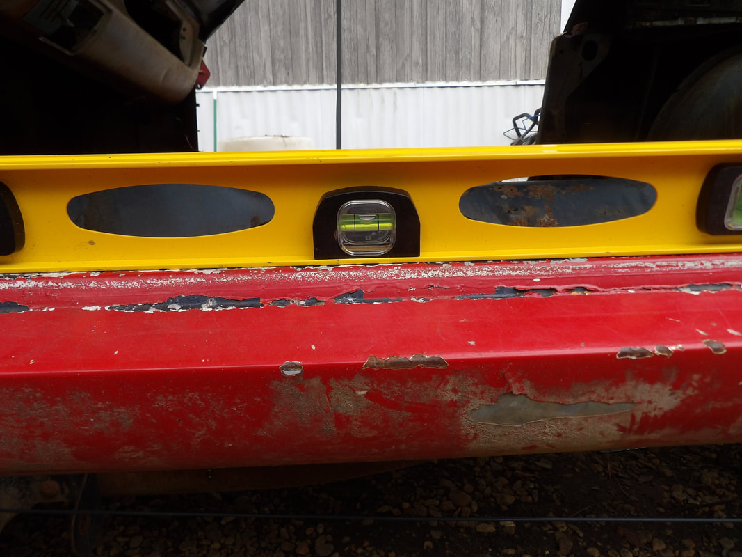 A level set on the rocker panel to verify the leveling of the body. 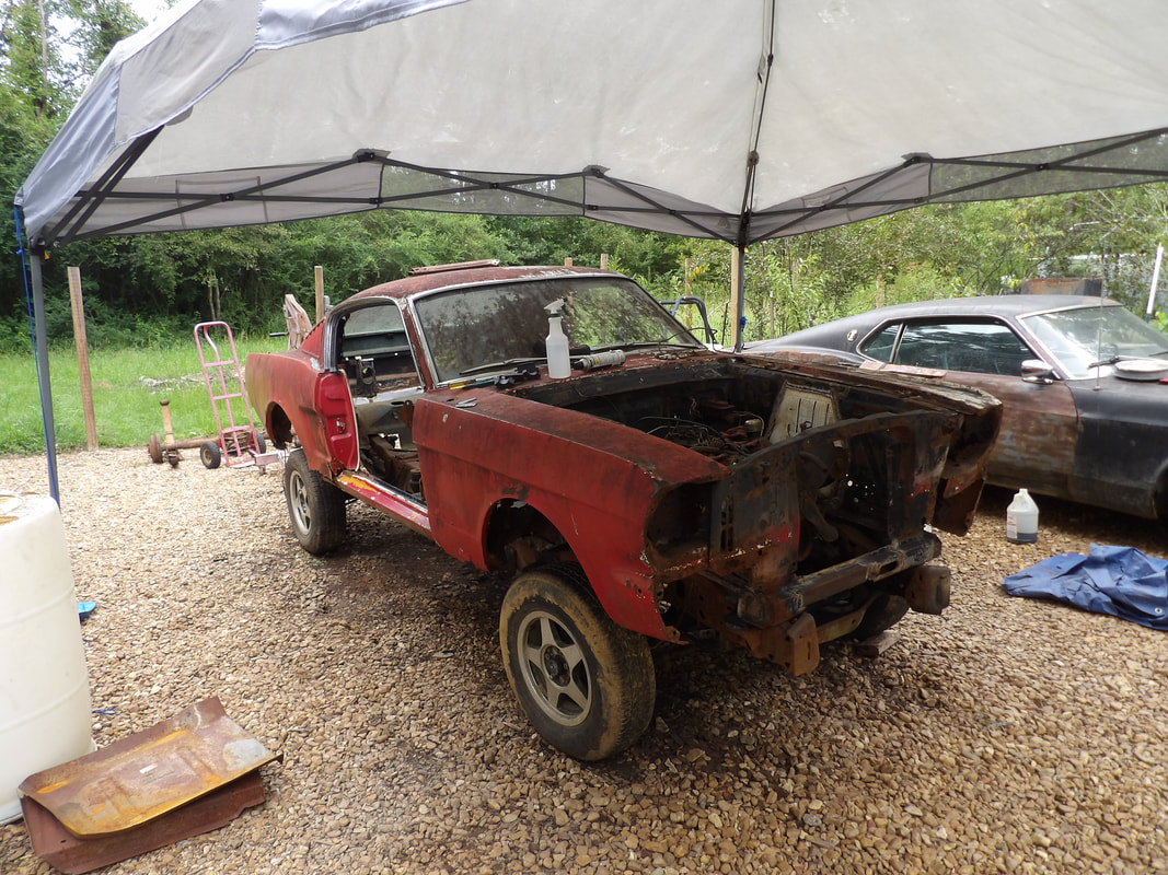 The Mustang body as it sits on the Ranger frame, the body is nice and level now, even though it rides high. 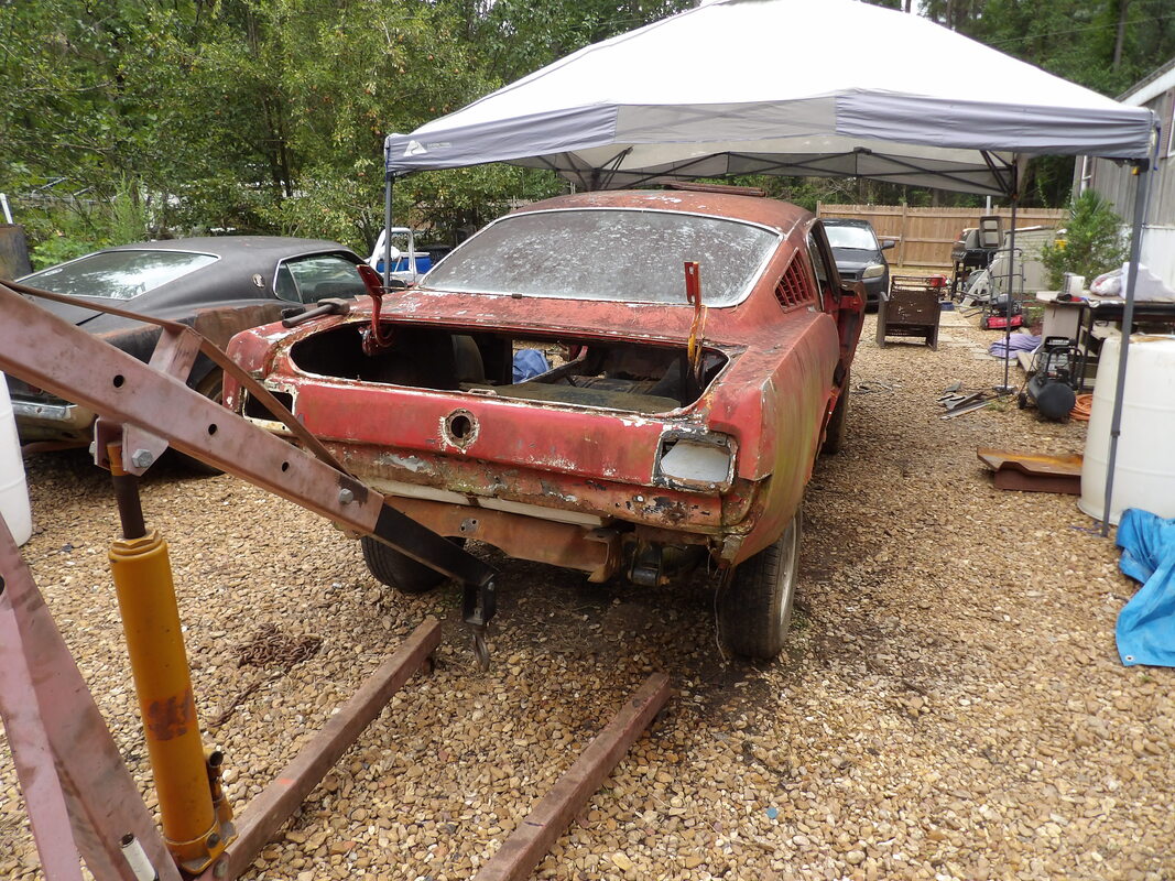 The crane is free from the body and the rear panel straightened out after bearing the weight on the crane boom. The rear of the body sits nicely on the rear of the frame with minimal gapping. With the body where I want it, I did take a moment to cut out more sheet metal from the floor pans, especially around the areas that were lower than the truck frame rails after cutting out the notches for clearance. Reason being, when I make patches for the floor pans, any sections below the truck frame rails will be extra metal that will be in the way and possibly dangerous if I had to work underneath. So, to prevent future lacerations, I cut out a lot of extra metal that was sitting below the truck frame rails to help level things off. I will have to add some angle iron and flat stock in select spots to provide the support to hold the patch metal so the floors will be solid as well as the mounting points for the front seats. Even with all this modification, I still need to look at the safety factor of making sure the seats are firmly mounted and solid points are provided for the seatbelt buckles. 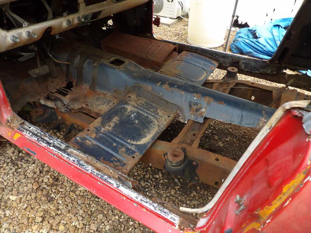 Extra metal cut from behind front seat mount and rear seat floor area as this metal sat lower than the Ranger frame rails. Note the same was done on the right front seat mounting panel. 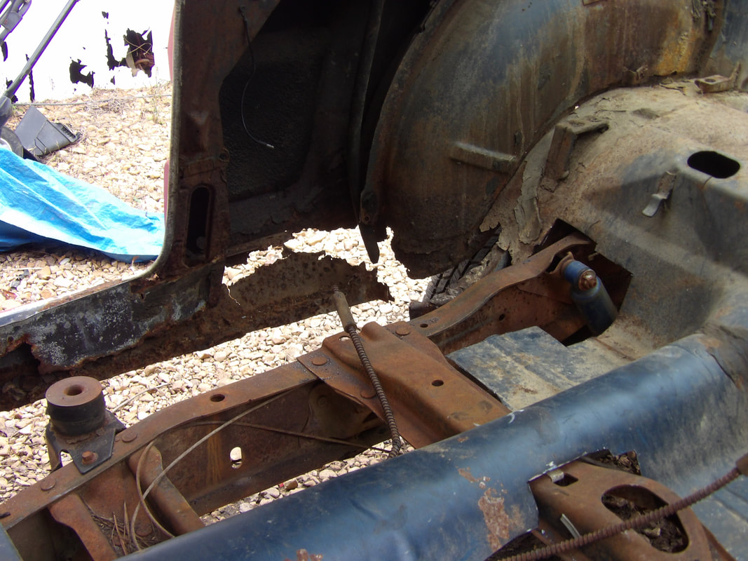 Extra metal cut away on the right side, including the remains of the torque box area, as none of this metal is good enough to be used as a welding point for any new metal, better to start off from scratch where the patching will be a lot neater and more solid. At this point the next move will be to start fabricating some mounting apparatus for the rear and the center points. There are two body mount brackets at the very rear of the Ranger frame in the truck area that I'll have to accommodate, possibly in the same way as I did the front mounts. I'll have to add some heavier metal around the trunk area to make the body mounts more solid. There's a pair of body mounts in the cab area that currently have old Ranger bushings in place but they're too thick and high to use on the current setup. I'll probably have to cut those out, and possibly cut them into thinner bushings for use on a new mounting setup for the center area. Since the old driveshaft hump area is higher than the actual driveshaft path, I will probably be able to run a piece of angle iron straight across without any concern for the future driveshaft hitting any of this. I have one more pair of body mounts just under the firewall that I'll have to accommodate as well. These are next to the rear sections of front subframes where I may be better able to do my setup with the long bolts to secure these points. The mounting is getting closer to completion.
With the angle iron pieces fitted in place on the front subframe ends, I took a couple 1/2" bolts, approximately 5" long, and welded everything together, the angle iron and bolts alike. Once the bolts were down, I test fitted the body once again in order to see how the studs of the bolts fit in the body mounts on the Ranger frame. At the same time, I took a couple large washers and fit them over the large holes on the body mount brackets. The right side body mount fit pretty good but the left side had the stud off quite a bit. I ended up cutting the protruding portion of the bolt stud and welded a second bolt forward of the old bolt so that new piece would line up properly with the body mount on the left subframe.
Bolt welded in place on right subframe to serve as body mount attachment.
Bolt welded on left side to serve as body mount attachment point.
The next move was to take the washers that I fit over the large holes on the body mount brackets and weld them in place. To make sure everything fit right, I lowered the body in place with the studs of the bolts protruding through the washers. Once everything was down, I welded the washers in place all the way around. I was able to lift up the body once again and prepare the rubber that would be used for cushions between the subframe and Ranger frame. 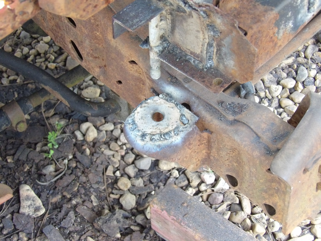
Right side body mount with washer welded in place. Everything on this side lined up pretty good from the start.
Large washer welded in place on the left subframe, along with the 2nd bolt that had to be welded forward of the old bolt. Also note how the bolt is at a lower position to allow more stud to extend down into the body mount bracket.
I took a piece of rubber and drilled a hole through the piece and slid the rubber onto the bolt stud, then added another piece of rubber next to the body mount bracket where the subframe would sit over the Ranger frame. This extra rubber would serve as an extra cushion along with the piece that's on the bolt stud. Once that was done I was able to lower the body back down onto the Ranger frame and secure everything with nuts and washers as intended, fully securing the front of the Mustang body to the Ranger frame. 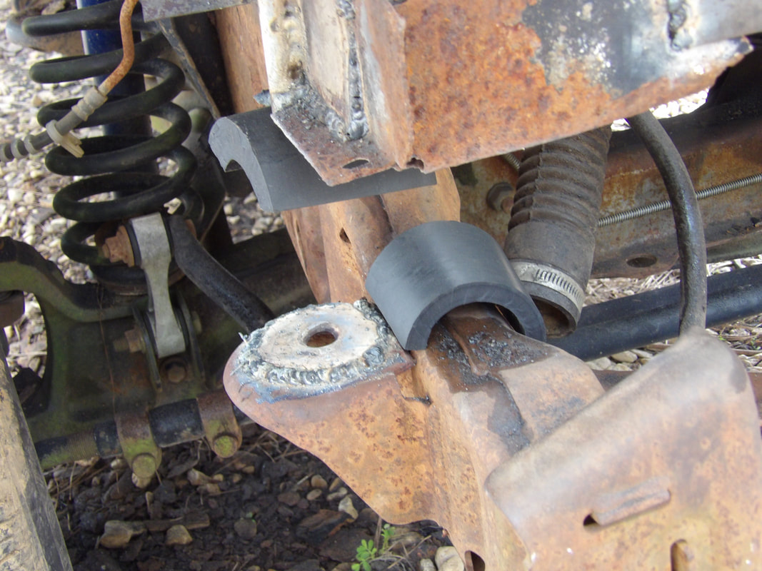
Right side body mount with rubber on stud and extra rubber next to mounting point for extra cushioning when the subframe is resting on the Ranger frame.
Rubber piece inserted over left body mount stud along with extra rubber piece to serve as an extra cushion.
With the front of the body secured, I moved the crane to the back of the car, ready to start work on the rear subframe mounting. I'll have to do some cutting back there just as I did on the front and of course I'll have to add metal in different places to reinforce the different areas of the rear to allow the body to be secured to the frame. As can be seen, its accepted that the body is going to ride high, much higher than the other Mustang, making this be a truck car. It's ok though. 
Supporting the rear of the Mustang body on the crane in order to remove the drums and board from under the body.
The crane is free of the body, with the rear of the body resting on portions of the Ranger frame.
Rear floor section leading up to old shock tower areas currently resting on the Ranger frame shock mount. This area will have to be cut out to allow the body to come down several inches in order to level it off to make the body level front to back. Currently the high rear has excess spacing between the subframe rails and Ranger frame rails.
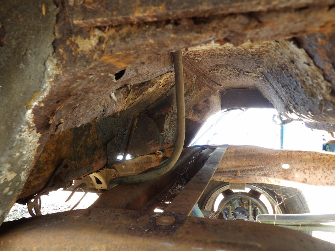
The interior showing the intermediate body mounts on the Ranger frame through the holes in the floor. Metal will have to be put in place around these mounts to reinforce the area to make it more solid of a mounting point for the body.
The intermediate body mounts on the Ranger frame will have to be factored in as well, warranting me to have to add metal to the cab floor area to reinforce the areas around the body mounts so I can be assured that the body will be securely fastened to the Ranger frame. This will have me simultaneously patching the floor as well as mounting the body, kind of killing two birds with one stone here. With the car riding high like this on a truck chassis, it does open the door to modifications that are more off road oriented, giving this car the kind of versatility it otherwise would've never had in its original form.
While trying to figure out an effective way to do the front body mounts for the Mustang body to the Ranger frame, I had to deviate some. Since the Mustang body sits on the tops of the Ranger frame shock towers, I wanted to add something that would help act as a cushion to lessen the effects of metal on metal contact. One quick way to do this that would be cheap yet effective was to add a couple pieces of old radiator hose under the tops of the subframes where they make contact with the tops of the shock towers. I cut a couple of sections of hose around 5 inches long and slit the piece lengthwise. I wrapped the hose pieces around the frame rails and secured them with a self tapping screw on each side. I lowered the body back down to the Ranger frame, verifying the contact between the metal was cushioned by the rubber hose. 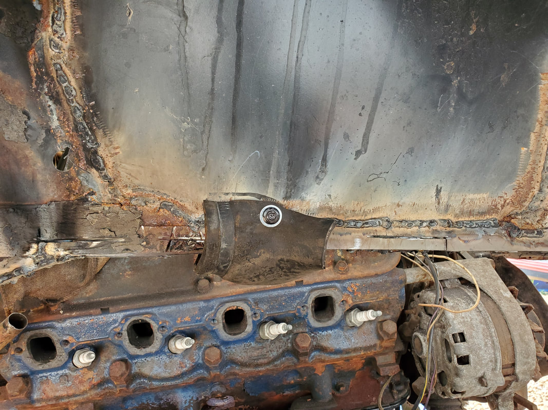 Piece of rubber hose attached over and around subframe with self tapping screw to hold it in place to cushion the metal on metal contact between it and the shock tower. 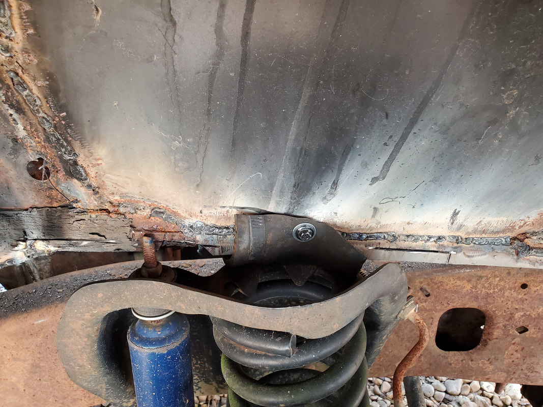 Piece of old rad hose secured with screw to shock tower patch and around top of subframe to cushion where the subframe sits on the shock tower on left side. The next order of business, as has been for a while, was figuring out how to do the front mounting on the Mustang body. The way I came up with to address this was to attach a 1/2" bolt, probably 5" long, to the side of the subframe where the stud of the bolt will extend through the Ranger frame body mount. This will obviously work to hold the body, but the biggest concern is the strength of the entire area. Since the section of subframe is nothing but some rigid sheet metal welded onto some rusty metal, I had to come up with a way to reinforce everything so when the frame flexes and twists the body bolts won't rip themselves and the surrounding body apart. 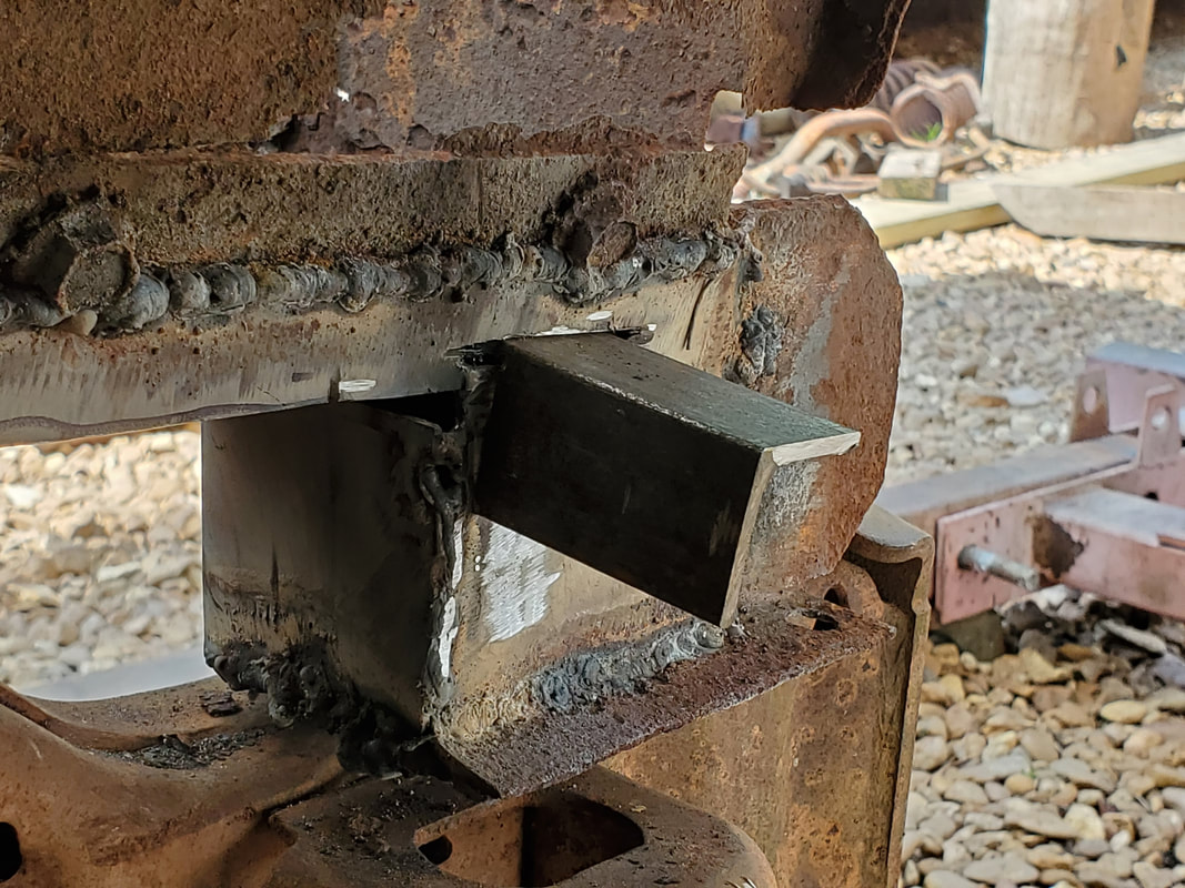 Angle iron piece inserted through groove over subframe on right side. Bolt will be welded to this to help strengthen the bolt and the overall mounting area when the body is secured to the body mount bracket on the Ranger frame. 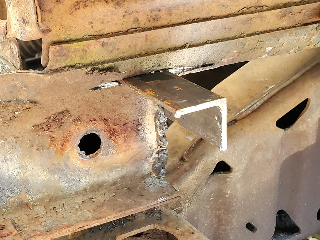 Angle iron piece inserted into groove on left side to aid in supporting the bolt that will be added for mounting the body. Even though the bolt will be welded to the side of the subframe, I thought of adding a piece of angle iron that would help in adding to the overall strength of the subframe area. Just welding the angle iron wouldn't be enough. I would have to somehow allow the angle iron to be attached to other points around the subframe box so the angle iron wouldn't just be ripped out from the welds. The idea I came up for this was to cut a groove above the subframe top, then cut a section of one side of the angle iron out, leaving a long tab on the angle iron piece. This tab would extend through the groove and across the top of the subframe in the engine bay. The tab would be welded down and the bolt would be welded to the angle iron that's on the outside of the subframe. All of this should hopefully give the bolt the strength needed to support the front of the body, even during twisting, and not rip itself apart. 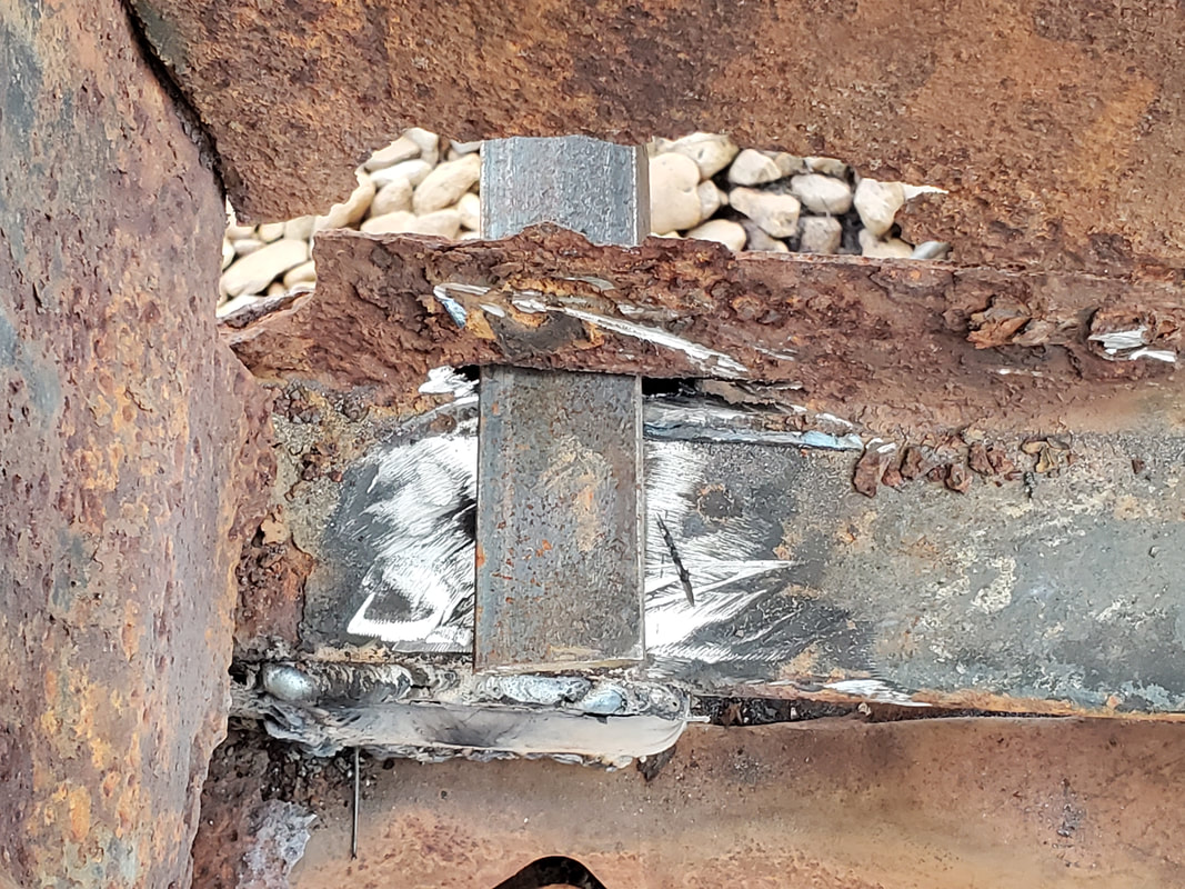 Tab on angle iron extending through groove cut over subframe on right side. Note bare metal ground down for welding. Also note the rust hole on side panel that will probably be patched just to fill the area in and help add just a minute amount of extra rigidity. 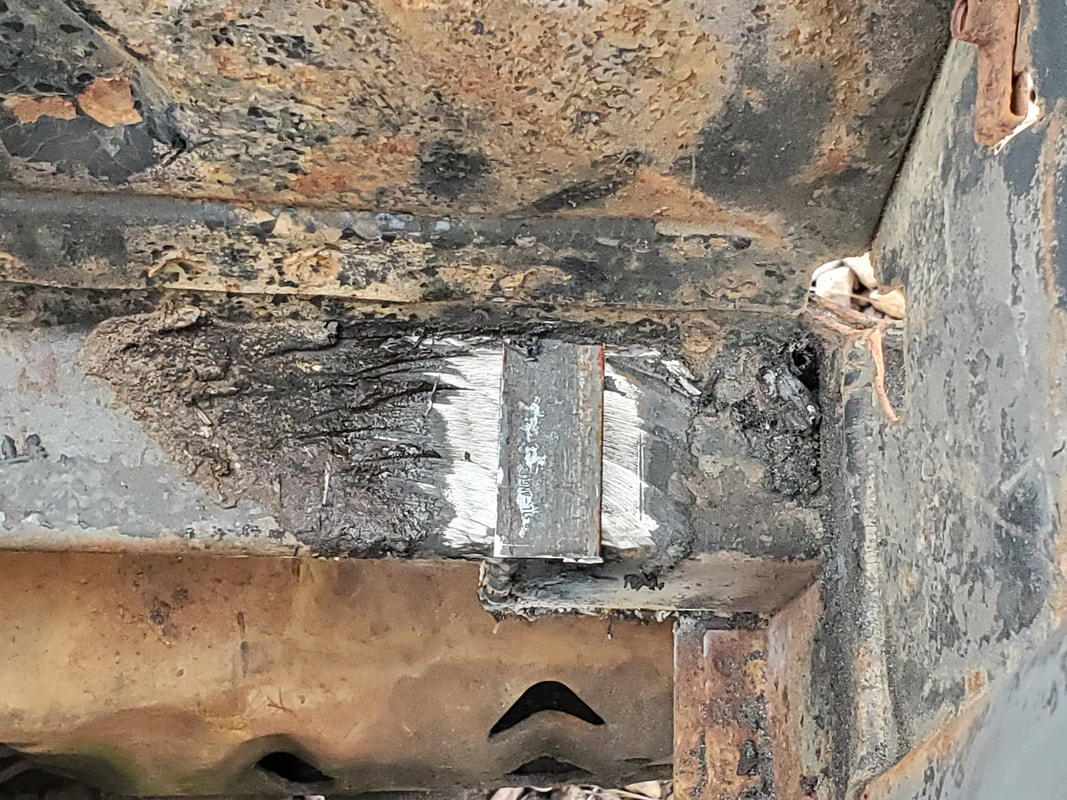 Angle iron tab extending through groove cut over top of subframe on left side. Note area ground to bare metal prior to welding in place. Once the bolts are in place, I can take some thick pieces of rubber I salvaged and drill holes through that to act as bushings to further cushion the front mounts. I'll have to find or make something that would help fill in the large hole on the Ranger frame body mounts so the bolt and rubber can fit in place without allowing the body to shift around within the huge hole. I may end up welding in some large washers over the large holes on the body mount brackets so the bolts can fit in place and not be able to shift around. Once this is all done, I can finally move to the back of the body and start work on getting that mounted. After the last analysis of the subframes and the way the body sat on the frame, I determined that I would have to chop out some more of the rear section of the front subframe where the bottom levels off at its lowest point. I also had to close in the open boxes of the subframes to more or less wrap up the work on said subframes so I can move on to getting the front end mounted to the Ranger frame. Unfortunately, the rear subframes are so rotted that I would have to patch up the metal in order to make them strong enough to continue to support the body. Since these subframes really aren't going to be load bearing in the way they used to be, it's really not imperative to close them in completely. I could've really forgone the whole deal of closing in the boxes of the subframes but the real reason is to provide smooth surfaces for the body to sit on the top of the Ranger frame. 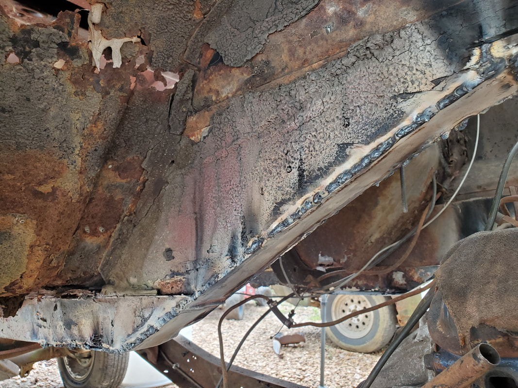 Left subframe with sheet metal welded in place to close in bottom portion of subframe box. Right subframe box closed in with sheet metal strip. Note the inside of the left subframe and how rusted the area is, preventing the sheet metal strip from being fully welded to the subframe box. 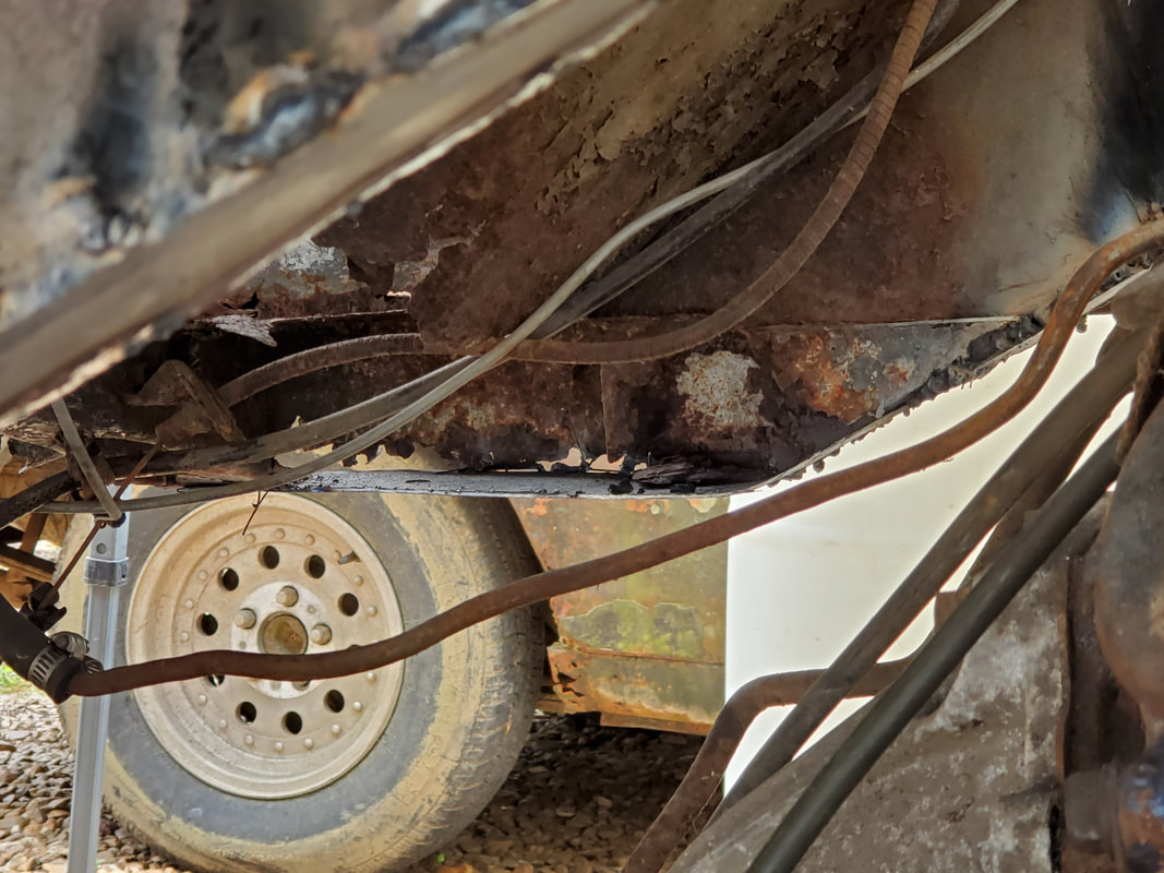 A closeup of the inside of the left front subframe at the rear point where its rusted out badly. Since this will no longer be a load bearing member, it's not critical to patch this. With the two subframes boxed in (at least as much as they can be done), I moved on to the front couple inches of subframe forward of the shock towers. These were pretty easy as they just required a couple small patches of sheet metal to be welded in over the open parts of the subframe. Once these were done, I was able to go ahead and lower the body down to check the fitting, mainly to see how the rear subframes sat over the Ranger frame. 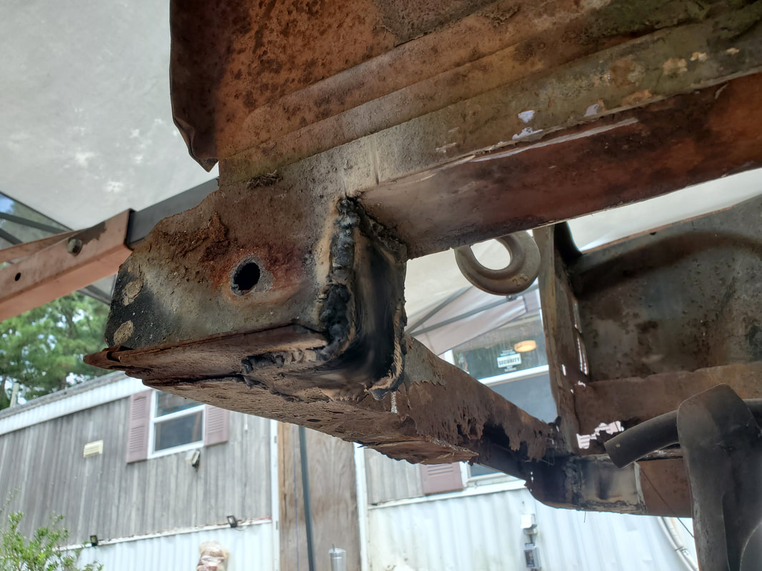 Patch on the left front point of the subframe rail. This is the area where the body mount bracket will have to be attached to secure the body. 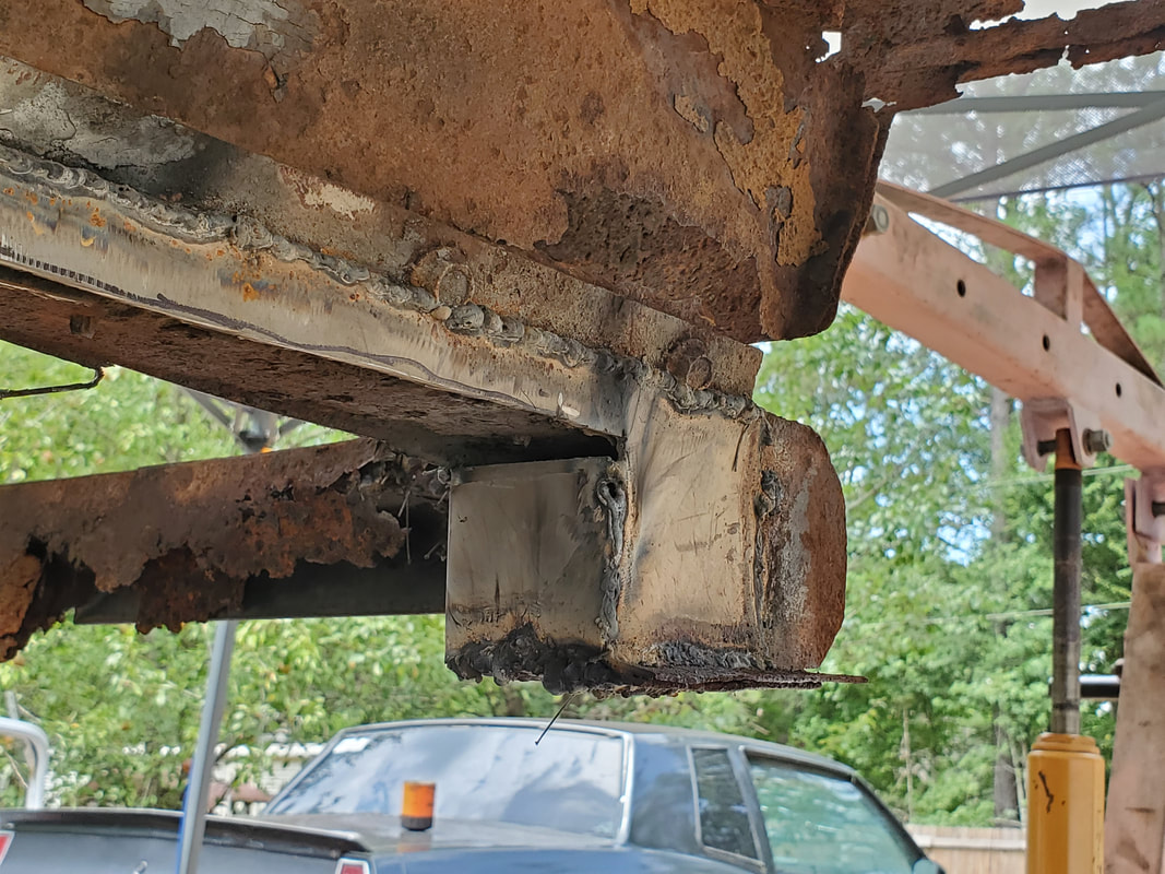 The same goes for the right side of the front point of the subframe. After lowering the body down and shifting it to clear the studs on the shocks, I found that the rear subframes had a fair amount of clearance between them and the Ranger frame. The front portion of the subframes also sat about as low as they would go. From what I can make note of, the Ranger frame may have a slight twist or distortion that has the left side not touching the Ranger frame while the right side does make contact. Then again the distortion could very well be in the Mustang's body, which was already clearly compromised. Even though these minute differences are noted, they are not so extreme as to affect the body and its mating to the frame. We still have that contact on the shock tower on both sides, and that contact point is the top parts of the subframes so for all intents, everything is even. These differences are to be expected as we're working with a questionable frame and questionable body.  The body lowered down onto the Ranger frame after making the final batch of changes. Compared to the Rustang to the right, the car does ride high. The spacing on the front fender and wheels also clearly shows this. 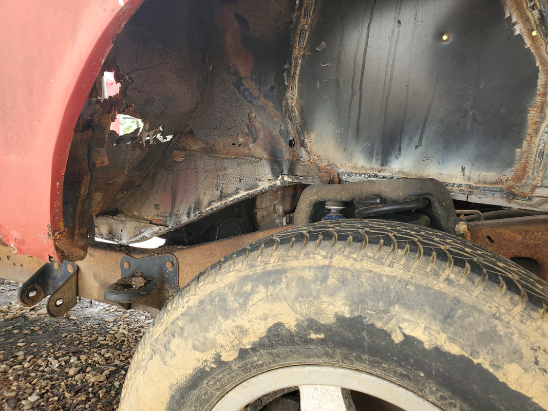 Closeup of the right side showing how the subframes are resting over the Ranger frame. Contact is still on the shock tower currently but will change as we work towards mounting the body. The rear point has more spacing between it and the Ranger frame after cutting out more metal. 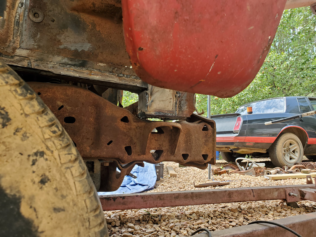 The right front mounting point section of the subframe is barely touching the Ranger frame at the very front. Body is resting on the shock tower. 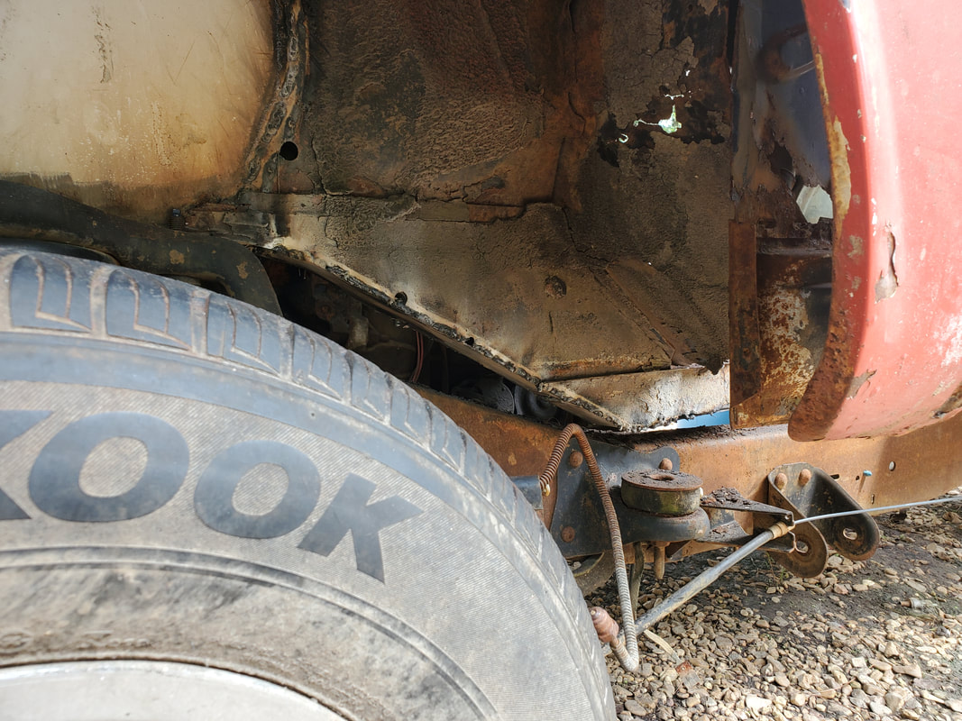 Spacing between the subframe and Ranger frame at the rear on the left side is better as well. 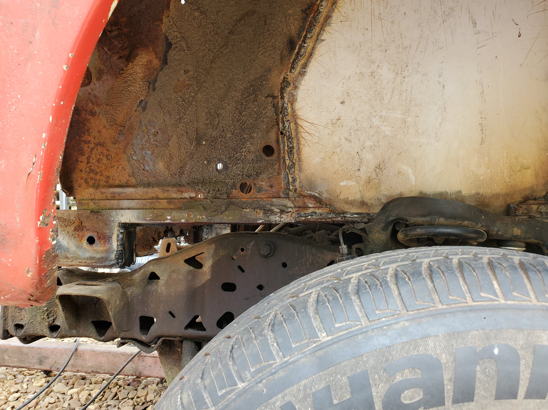 The front most point of the front subframe has a little more spacing between it and the Ranger frame compared to the right side. Everything is still resting on the shock towers.  A shot of the top of the right subframe as it sits over the Ranger frame, showing the difference in positions. The subframes have a slightly wider spacing compared to the Ranger frame rails. At this point, I'm ready to start fabricating the body mount brackets. These pieces will have to be strong enough to support the weight of the front of the body at the front, while also being mounted strongly enough that they won't just break free or break the subframe or any part of the unibody attached at this point. I'll have to add some extra metal around and probably through the side panels to help hold the brackets solidly enough that they will hold. I may even add extra metal that will further attach to the tops of the subframes and onto the side panels, in much the same way the shock towers were spot welded at the different points to ensure strength all around. As cheesy as it sounds, I can also use old hose as a form of cushioning between the Mustang body and Ranger frame to help eliminate the metal on metal contact that the two bodies may make at their different contact points while still having the body secured. Again, this is that shooting from the hip concept that is subject to constant changes all thorugh the project. We're pretty close to having the front end of the Mustang body where we want it, or at least close. I still have one more opportunity to cut out some subframe metal before I get to the point where I can no longer cut out anymore without having to actually cut out the top portion of the subframe boxes where they attach to the side panels. After thinking about it, I figured this wouldn't be a good option as the weakening of the engine bay area would make it more difficult to get a solid mounting at the front body mounts on the Ranger frame. The top part of the subframe boxes is actually pretty strong and as long as the metal is present, I'll be able to mount brackets to the body to secure it to the Ranger frame. Even the thought of building a tubular frame wasn't really a viable option because the tubing I would need is not present and that option is a rabbit hole I don't want to fall down. Once I get to the point where I'm cutting out all the structural integrity of the body to add tubing, I get to the point where I might as well just build a full tube chassis and further cut the body up to fit around what amounts to a dune buggy. Like I said, rabbit hole. 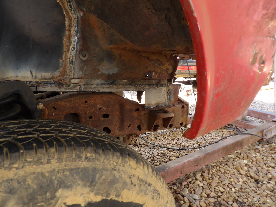 The front section of subframe that remained after cutting out more of the subframe metal. This allows the front of the subframe to sit on the Ranger frame. Note the contact point of the top of the subframe resting on the Ranger frame forward of the shock tower. 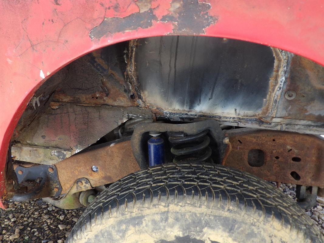 Right side subframe at the rear point, almost but not actually making contact with the Ranger frame. Note the shock tower and the shock stud where it sits relative to the subframe. Note the contact point with the frame just forward of the shock tower. I cut enough metal from the front of the subframe to leave a few inches of the very front of the boxes for mounting brackets later. I cut as much metal as I could from the very top of the subframes to help better clear the tops of the Ranger frame shock towers. There is a minor contact point on the Ranger frame just in front of the shock towers. I cut enough metal away from the point on the rear of the subframes where the downward slope levels off so that these points aren't making contact with the Ranger frame. It's very close but not metal to metal. After lowering the body down and shifting it, I found that I was pretty much as far down as I could go with the front of the body. 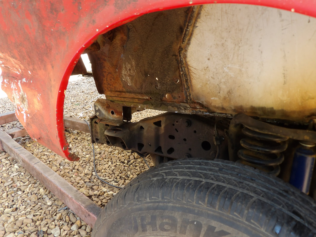 The very front of the subframe that remains after cutting out the metal to allow it to rest on the top of the Ranger frame. 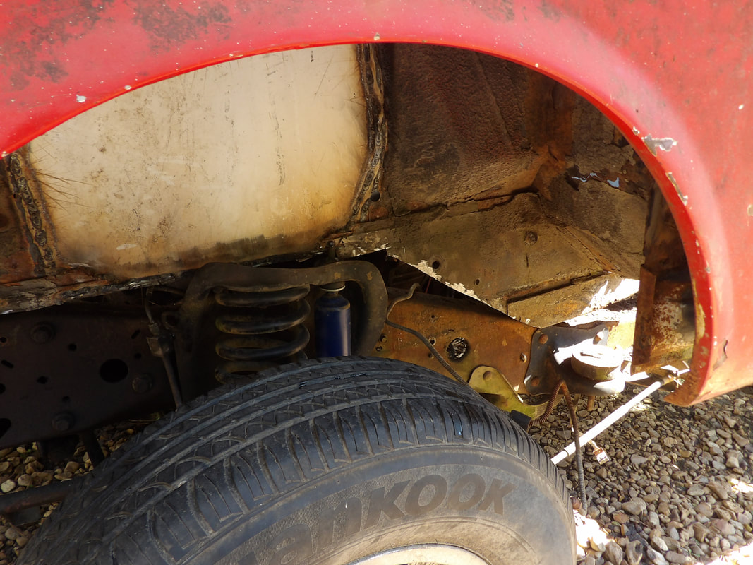 The angled section of the rear of the subframe as it sits over the Ranger frame. It doesn't look it, but its not making contact with the Ranger frame. Note the stud of the shock and where it rests relative to the subframe. I can now start working on the final steps of the front end. This will involve closing in the open subframe boxes by welding in metal on the bottoms of the subframes. Once those are closed in, I can then start fabricating body mount brackets to attach to the body. Even though I'll attach these to the remaining section of the front subframe, I'll have to add some extra metal around the subframe, which might involve cutting into the sidewall to add metal around the entire box subframe. I may be able to figure out some extra reinforcement metal around this area to make the mounting points sturdier once I install other hardware like the radiator and battery tray, among other things. 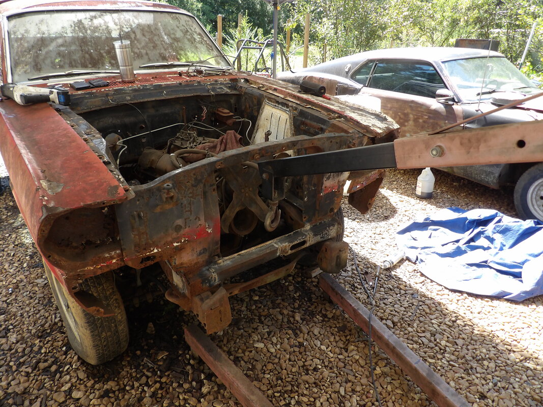 The body lowered onto the frame, making full contact with the frame at the very front. Another thing I have to consider regarding the final mounting of the front of the body to the Ranger frame is if I may need to cut a little more of the rear subframe out. Reason being, even though the angled section isn't making contact with the Ranger frame right now, when I start lowering the rear of the body, it will also cause the front third to go lower as well. The angled section will then make contact with the Ranger frame and act as a fulcrum, causing the front of the body to raise up some as the rear goes down more. This may compromise the mounting of the front of the body, and may even risk distorting the body once everything is secured in the rear, even if I do get the rear down as low as I need it to be. This means I'll have to do one more cut at the rear subframe at the angled section to make it ready so none of the mentioned problems surface. |
