|
Now that I'm in the home stretch on the mounting of the powerplant on the Ranger frame, there's the matter of making a transmission crossmember to secure the back of the rig. At first I was going to source some angle iron with which to use to make a crossmember but then I thought about looking in the scrap pile of auto parts to see if there may be something that I could use to make a crossmember. I gambled on the hope that I could find an old crossmember from another vehicle that I stripped and I was successful in that field. Looking at the pile of parts from the minivan, I ran across its old crossmember. While this piece is way too big to use in its original form on the narrow Ranger frame, that doesn't mean that I can't cut and trim and weld to make a crossmember. On the minivan crossmember there are two mounting tabs on the piece that are spaced at some weird positions. In its original state, this piece is absolutely useless on the Ranger frame with a SBF V8 powerplant on board. 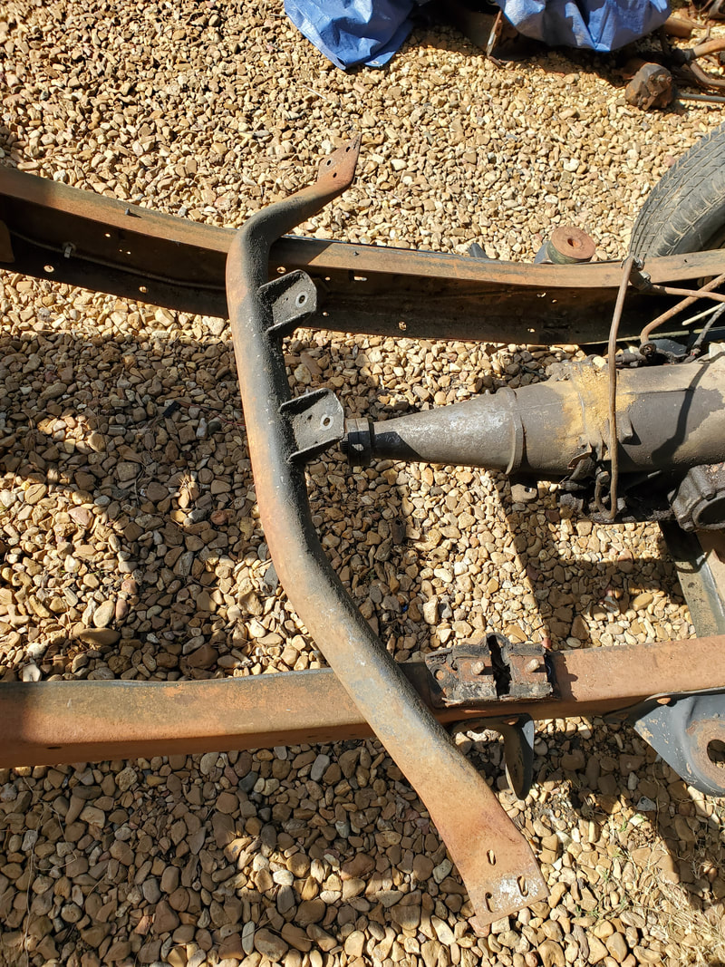 The minivan crossmember as it originally is, note the two mounting tabs on the crossmember body. First thing I had to do was cut those two tabs from the crossmember. The transmission mount on the C4 incorporate two studs that secure it to the mounting base on the car it would've been used on. My plan ended up being me taking the two tabs I cut from the minivan crossmember, trimming one end of each piece, then butting the two pieces together, side by side, and welding it up. After I cut a wing off each side of the two tabs, I mounted the tabs on top of the studs on the C4 mount, then started welding the two pieces together. Once the two pieces were welded together, I was able to remove the new base piece and move on to welding it to the base crossmember. 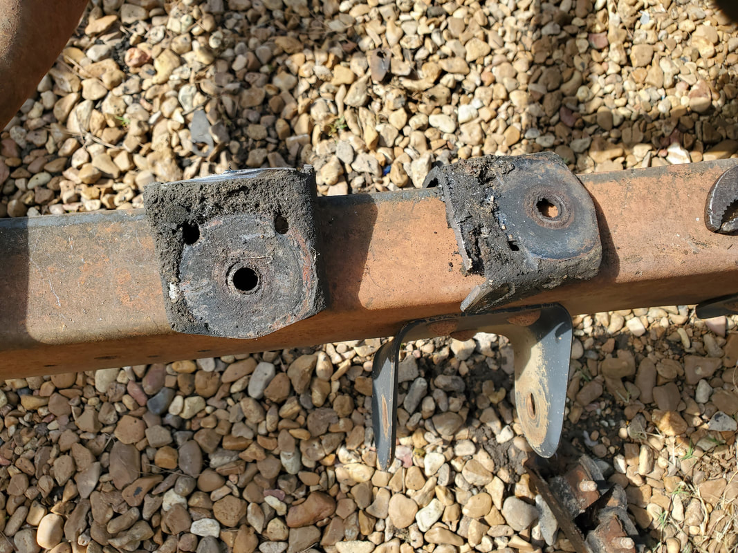 The two mounting tabs cut free from the crossmember, these will be welded together to make a single mount base for the C4 transmission. 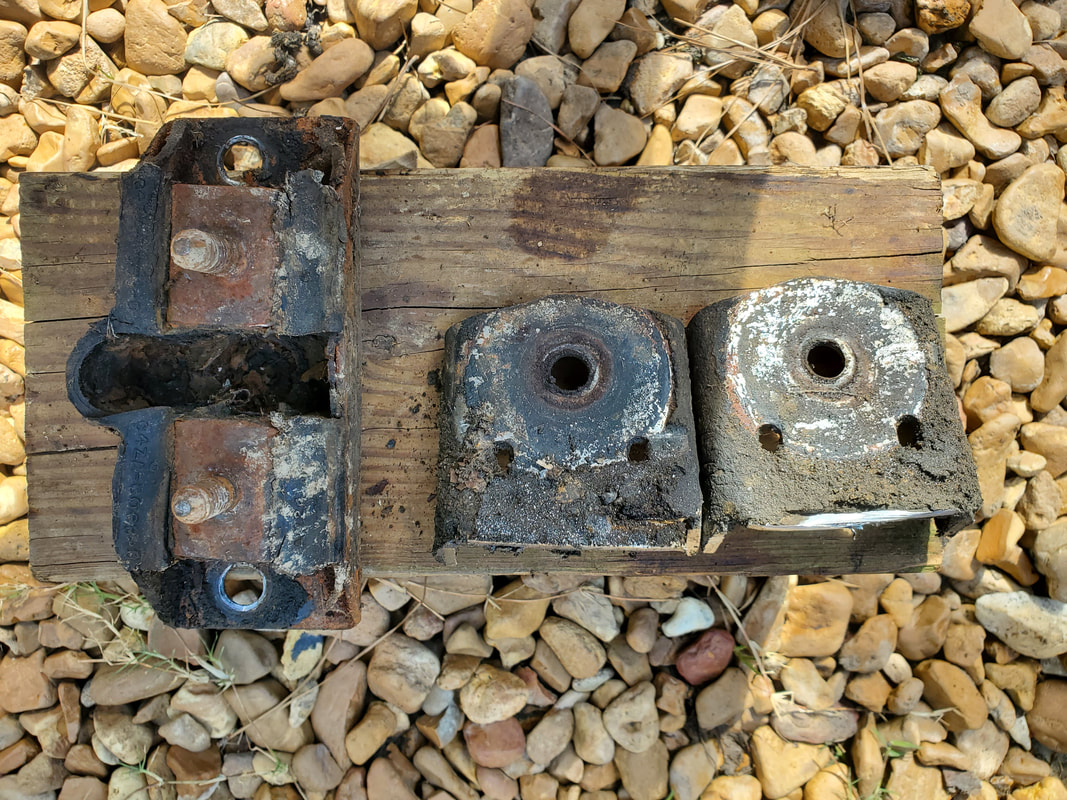 Sizing up the two tabs with the transmission mount to get an idea of how much of the wing on each tab I'll need to cut off. 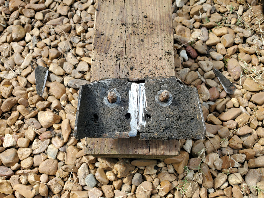 After cutting a wing off each tab, I put the tabs on the studs of the transmission mount to get a final trim done before welding the two pieces together. 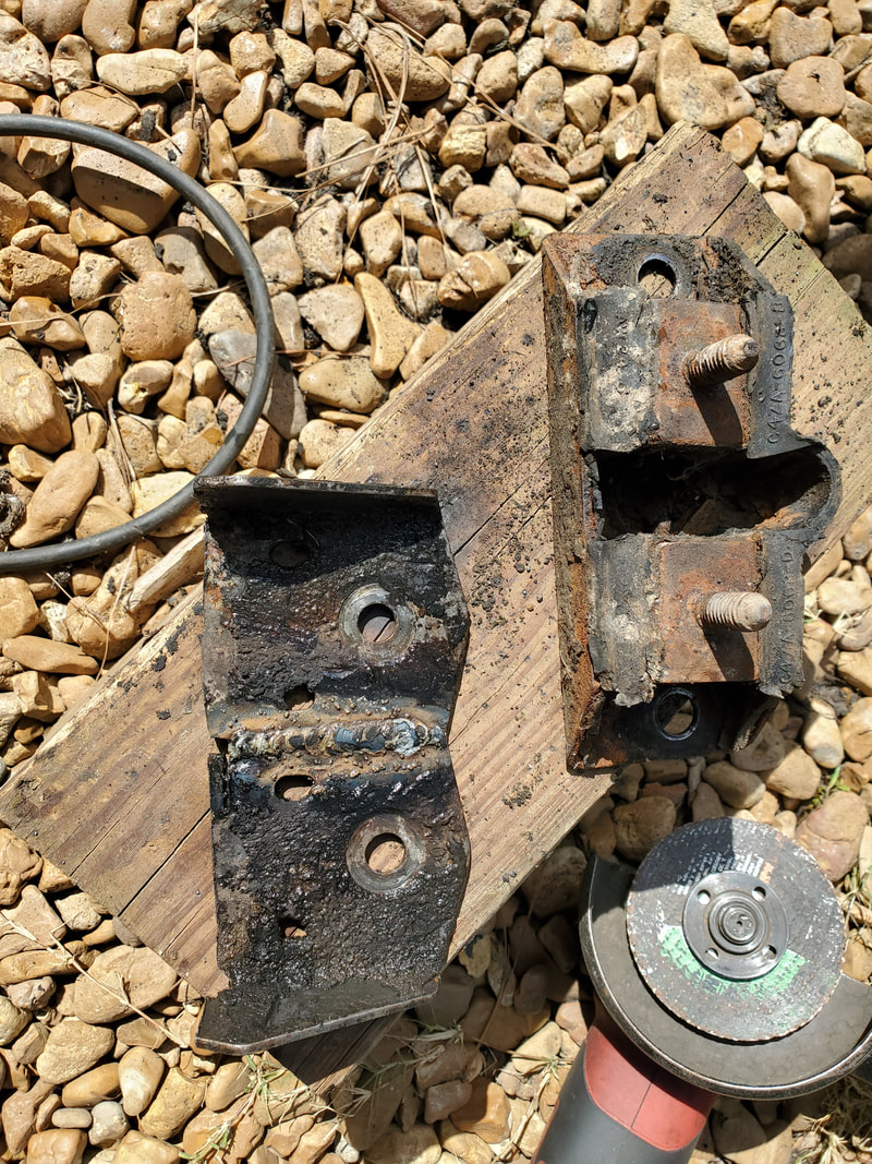 The two tab pieces welded together on both sides, making a single mounting base for the transmission mount. With the transmission mount base done I had to figure out how to make the base crossmember fit in our new configuration. The solution I had to that was to cut the outer thirds of the piece off, leaving the center tube piece. I then wend on a tangent and welded the mount base to the center tube, with the intent of being able to hang the tube under the transmission in order to gauge where the two end pieces would have to go. 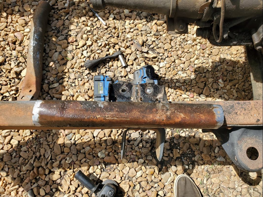 After welding the transmission mount base to the center of the crossmember, I cut the end thirds from the piece, leaving just this center tube, which will be bolted to the mount which will be bolted back under the transmission. Because of the way this crossmember is made, when I trim down the end pieces to be able to mate them to the ends of the center piece, things will not perfectly mate up. I'll be able to weld things up either way, but in the end, the whole works is going to look pretty tacky, all things considered. Of course, with projects like this, tacky is pretty much a norm, especially when there isn't even any aftermarket hardware available for this level of customization. I could utilize shop equipment like tubing benders to bend tubes to make a crossmember, but we don't have that luxury. Hell, I'm building the car in the middle of a gravel covered driveway so yeah, tacky is going to be the word of the day here. 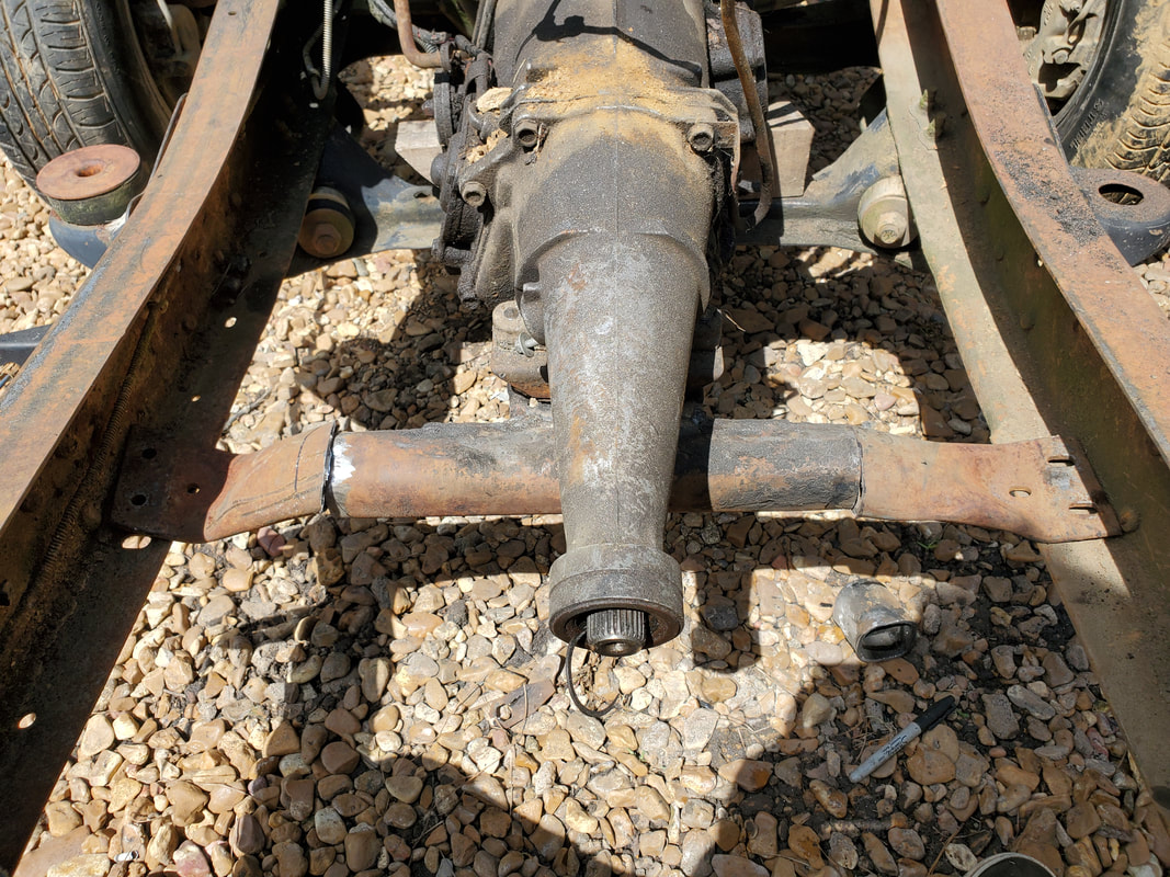 After trimming the end pieces of the crossmember, I fit the ends to the ends of the center tube to get things staged before starting the welding. I will jack up the tail a little to get the right angle prior to beginning the welding. I took a jack and put my wood block on it to jack up the transmission a smidge to get a better angle, relative to the rear end, then trimmed the end pieces to be able to mate them to the ends of the center piece. I'll weld these together next and drill the holes on the frame to add the bolts to hold all this garbage together. Once I remove the jack, the transmission will be completely suspended on the crossmember. I'll finish things up by welding the motor mount brackets as I stated I would do previously in order to finish up the whole powertrain mounting phase of the project.
0 Comments
With the powerplant down at the build site and staged to go in, the first thing I had to do was remove the old engine mounts from the Ranger frame. This involved removing the mount brackets from the frame, which involved two large nuts on a double stud piece and a single bolt with a wing on it and a nut underneath the frame. I ended up chopping the single nut and bolt off before realizing what this was, but the two large nuts on the double stud piece were zipped off with the impact wrench. Once the brackets were off, I zipped off the single nut on each engine mount, removing those two pieces. The first thing I did for shits and giggles was see if there was any possible way the engine can sit right on the frame and use the tabs on the 289's mounts. This proved to be pointless, so I ended up reinstalling the Ranger engine mount brackets. 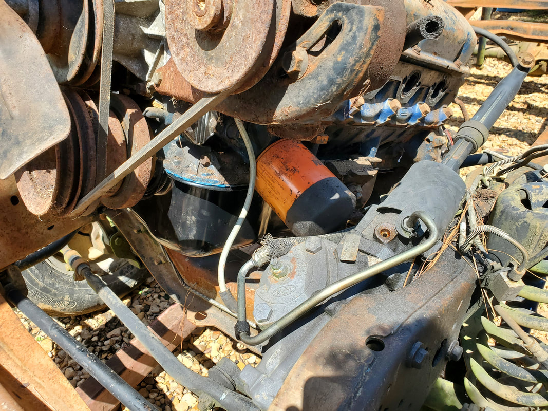 Initial test fit was a failure due to the oil filter hitting the steering gearbox. It will have to come out and be replaced with a remote oil filter assembly. When I situated the engine over the frame, I noticed the first roadblock. Even though its small, it's still a roadblock. That roadblock is the idea that the oil filter sits right where the steering gearbox is located on the frame. Because of this, I would have to remove the filter to allow the engine to sit on the mounting brackets on the frame. I will have to source a remote oil filter kit for this engine. This incorporates a plate that is secured over the oil filter base on the engine, has a couple hoses plugged to the plate and to a remote base that holds the oil filter away from the engine block. Such a kit should not be too pricey and will solve this first problem. 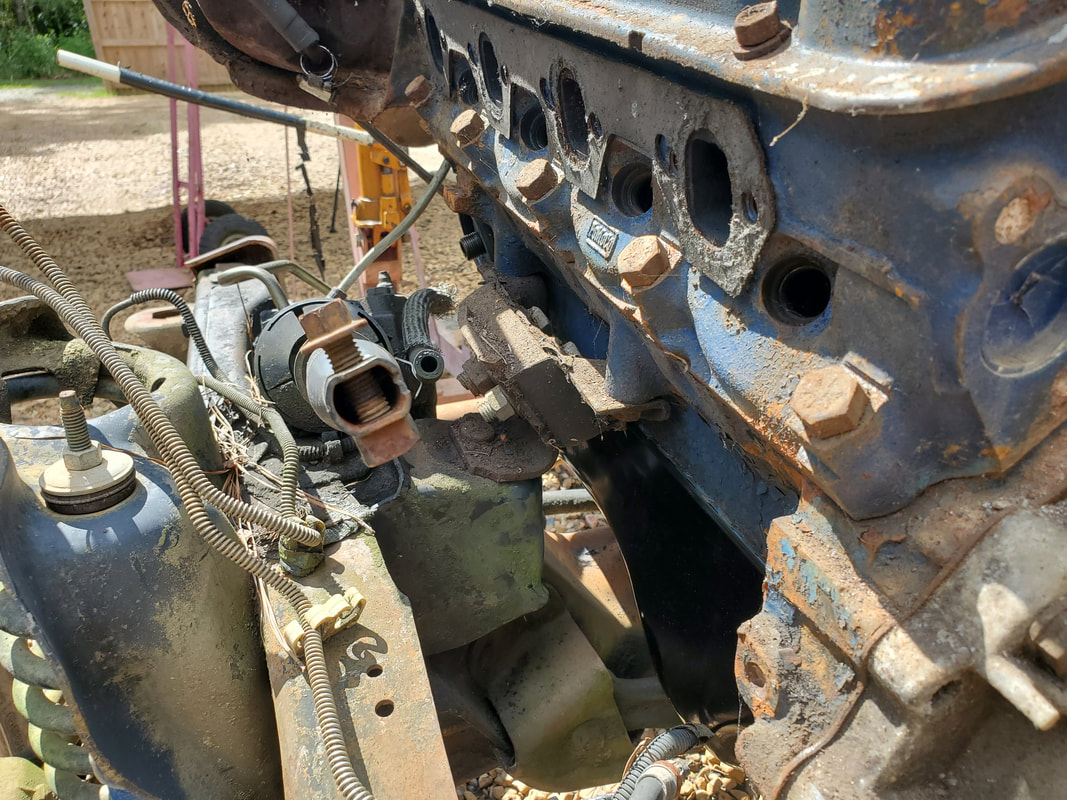 Second fitting of the engine on the Ranger motor mount brackets. Everything seems to fit fairly well, whether this mess can be fully secured is a whole other matter. 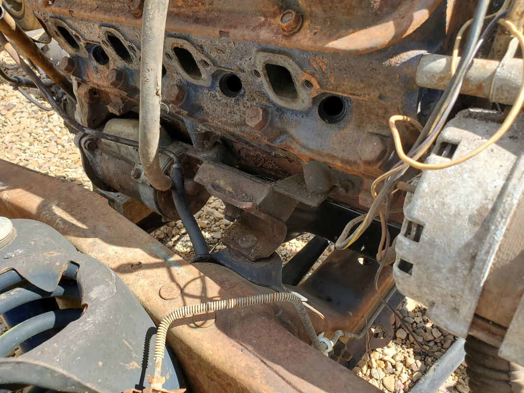 Right side motor mount with engine resting in place, not fully secured. Upon setting the engine down on the Ranger frame motor mount brackets, I noticed that the engine had a lean to the right side. The motor mount brackets on the frame were not at the same level, with the left one being higher than the right one. Even though this would've been a minor inconvenience, being a stickler for details, I wanted to correct this. The only neat way to do it was to remove the left mount bracket, cut the top off, trim it some, then weld the top back on, which would put the left side at a lower level than before, and should help level the engine as it sits on the frame. 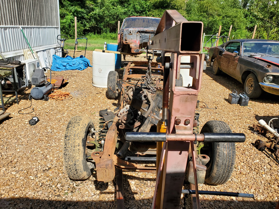 Engine after getting the left side engine mount cut down and welded together for a test fit. After trimming the main part of the motor mount bracket down, I burned a couple small welds to the top so I could test fit everything before welding the thing completely. My test fit looked better than before, not perfect but better than before. I didn't want to keep trying to cut too much from the bracket otherwise things might not fit right, even more so than we're already looking at. With that, I welded everything up then moved on to the next stage in the installation. 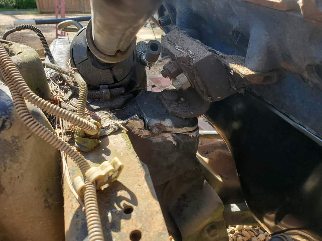 The cut down Ranger engine mount bracket with a couple of small welds to test fit the whole works prior to final welding. 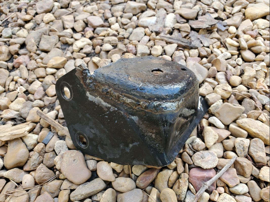 Welded up Ranger engine mount bracket after the cutting down. With the oddball way the Ranger engine mounting setup is done, I found that I was unable to tighten up the stud on the 289 mount bracket as it sits in the Ranger mount brackets. None of the pieces were made to fit perfectly flush with one another, I could only get a partial fitting. In order for me to secure the Ranger mounts back to their bases on the frame, I had to leave the nuts on the 289's mount studs loose enough to give me the wide angles that would allow everything to "fit". 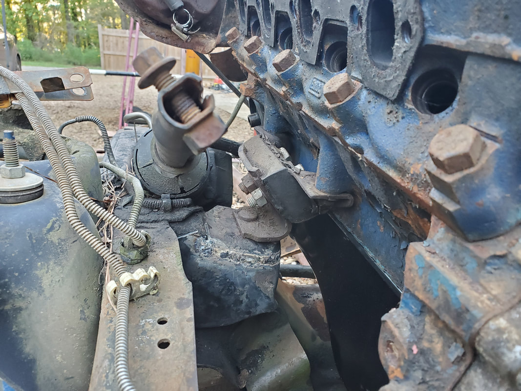 Left side engine mount, after welding piece back up and setting the engine down, without tightening the stud. 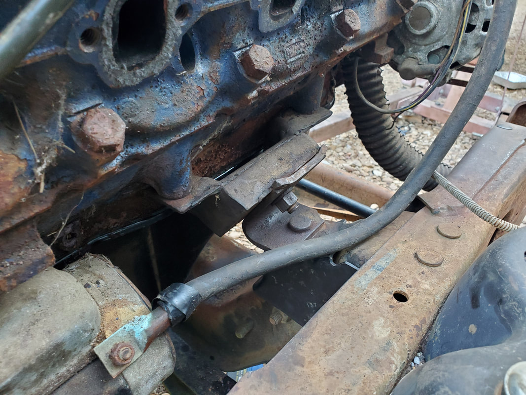 Right side engine mount with the engine resting fully on it. Stud is not tightened down in order to make everything fit. That will have to be addressed.... After wrestling with trying to get all this garbage to fit together, I had to settle on having the loose fitting 289 mounting brackets on the Ranger mounting brackets. I added some shims in a vain attempt to try and tighten the studs down against them to maintain the angles, but even that didn't work out. With the engine down on the brackets, I figured the only easy way to remedy this shitshow would be to weld the 289 brackets to the Ranger brackets then have the engine mounts themselves be permanent. Since one of the mounts are already set up to be a permanent setup, I'd just have to bolt down the other one to make it permanent. In order to remove the engine I would have to remove the two bolts securing each engine mount straight to the block. Hopefully by welding everything in place with the engine in place, everything will fit. Of course, I could just replace both engine mounts and the flex of the mounts would give me the play that would allow me to get the bolt holes lined up to install the bolts to the block to hold everything together. 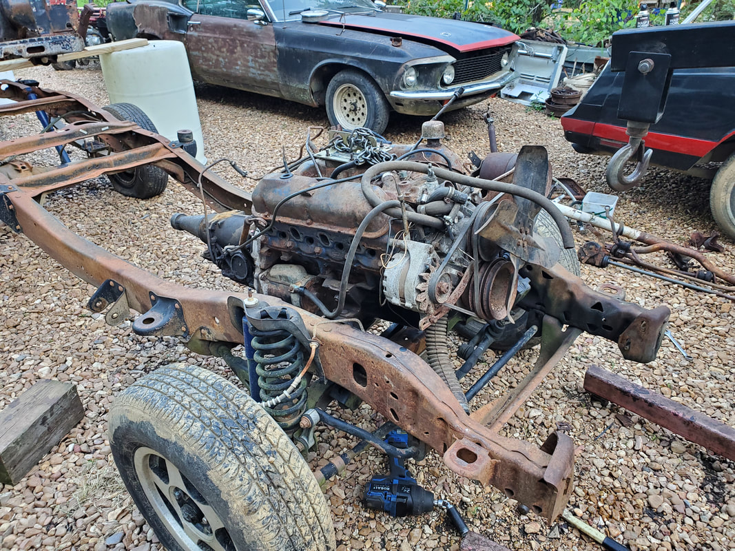 The engine in place on the frame, freed from the crane and fully resting on the mounts. 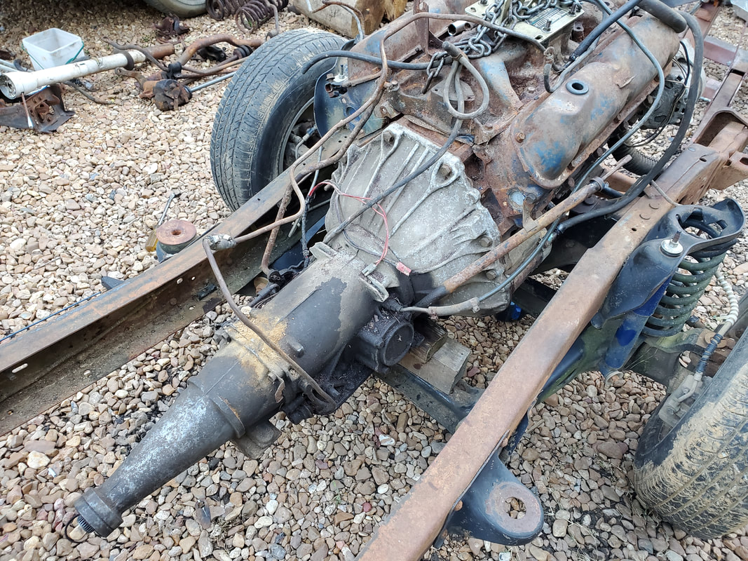 The transmission is propped up by a couple boards to keep it at an angle that's going to have it in line with the rear end. Once I get the engine mounts finalized, I will need to gather up some metal to start the fabrication of a transmission crossmember. Now, I could use one of the other crossmembers I may have laying in the auto scrap pile and just cut and weld it as needed, along with drilling several holes in the frame to secure the crossmember. Once I get that piece made and secured, I can write off the engine mounting part of the project and move on to actually mounting the body to the frame. With the engine in place, I will definitely need to see how the body fits relative to the engine to determine just how low on the frame the body can sit. I can't put the body too low, otherwise the top of the engine may stick up above the engine bay on the body, not allowing me to install an air cleaner, much less install the hood. Of course, worst case would be installing a cowl hood to make up for the higher sitting engine. Other option will be mounting the body at a height where the wheels will have a good amount of clearance between them and the fender wells. In that state, the car would indeed look like a truck/car. Of course, as stated before, this whole project is a shooting from the hip type of project, very little real planning is going on here. I'm just looking at the setup and figuring things out little by little as I go along. Since the Ranger frame and suspension is set up to accommodate rear sump engines, I would have to make some changes on the 289 in order to make it ready to go into the frame. Vintage Mustangs and other cars used front sump oil pans so I would have to swap that out. Of course it's not that simple as I also have to swap out the oil pump pickup. To fully secure the pickup, I would have to remove one of the main bearing cap bolts and reinstall it over the loop on the pickup tube to hold it in place. Of course this also meant torquing down the bolt once again. Normally the vehicle that would've used this setup would've had a main cap bolt that had a stud end to accommodate a nut to hold the pickup tube but we didn't have that luxury. 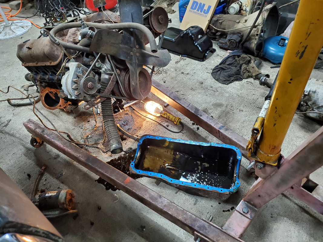 Old oil pan removed from the 289, surprised to find that I had installed a newer one piece oil pan on this engine a long time ago. Gasket is still useable. 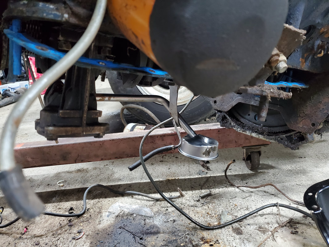 Rear sump oil pump pickup tube/screen installed. Note main cap bolt holding the tube in place. At first, I pulled the oil pump, not knowing if I might have to replace this oil pump since this engine is a 65 year engine and the pickup tube is for a 90's range engine. Everything turned out to be compatible, so I made another gasket and put everything back on, adding the pickup tube. The next order of business was the oil pan gasket. Originally this engine would've used the typical four piece gasket set, but these are a pain and Ford started using one piece rubber gaskets in the 90's SBF engines. Apparently when I worked on this engine and this car many years ago, I actually added a one piece gasket so when I took everything apart, I was pleasantly surprised to find this one piece gasket still intact, allowing me to reuse it and save the new gasket I got specifically for this job. This gasket is easy to install, just needing four guide studs that screw in place at the four corners of the block and timing cover. The gasket slides over these studs, which are flared to hold the gasket in place to allow one to install the oil pan without having to keep four pieces of gaskets straight. 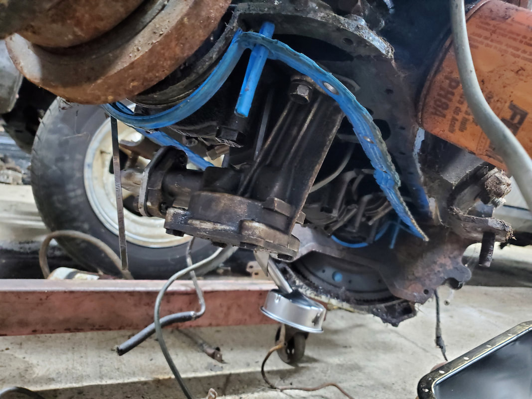 Shot of the guide studs on the front corners on the timing cover, used to hold the one piece oil pan gasket in place. Rear stud can be seen in the back of the engine holding the back part of the gasket. With the oil pan slid over the studs, I placed bolts at various points around the pan to get the unit mounted up evenly. I was able to put a little more torque on these bolts with this gasket compared to the cork gasket pieces of the older style. The cork would pinch out with the slightest amount of extra torque. The one piece gasket took extra torque without distorting or pinching out. With the gasket in place the 289 is now ready to be relocated to the build site for transplant into the frame. 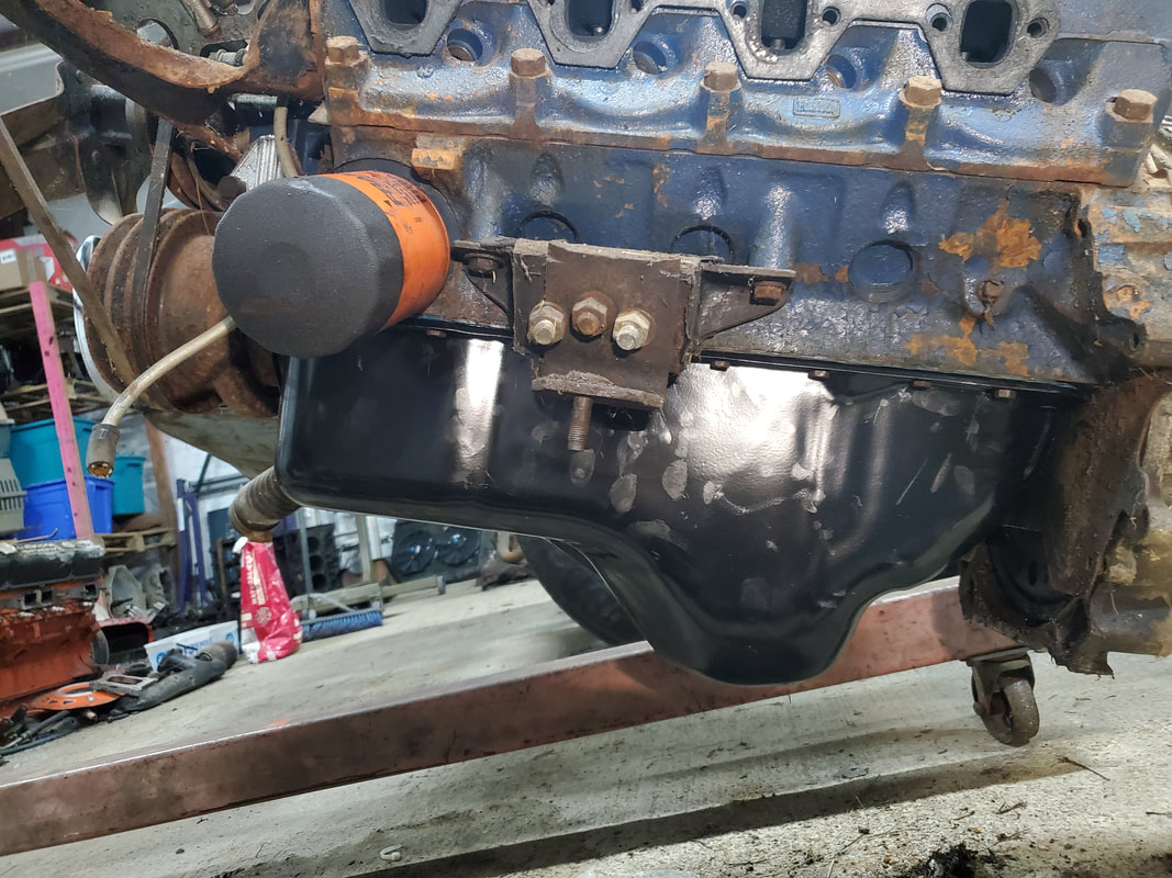 Side view of the rear sump oil pan and the makeshift permanent motor mount that I made from the broken mount. I added the extra bolts to hold the two pieces together for a permanent fit. 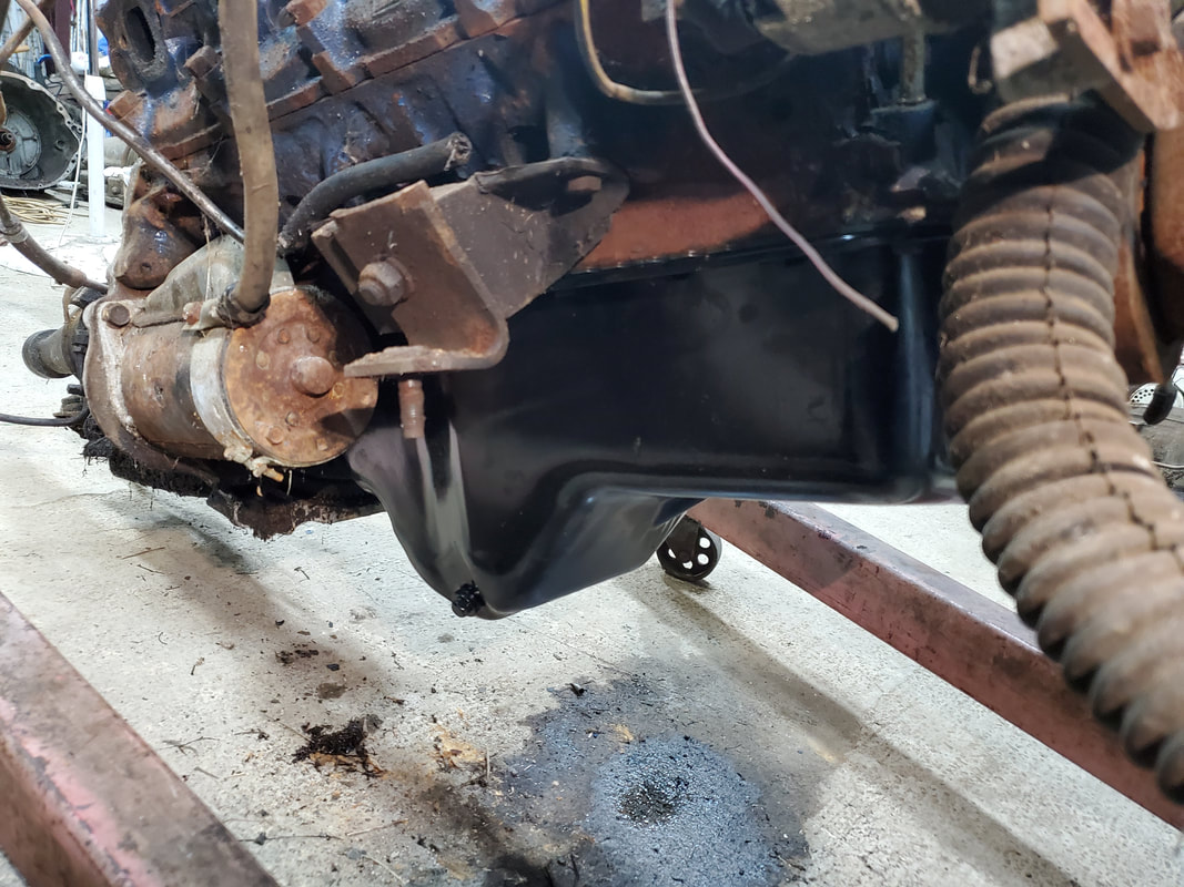 Another angle to the rear sump oil pan. Also note the motor mount plate that's secured to the main motor mount and sets on top of the mounting bracket on the vehicle. Since the engine was already hooked up to the crane with the carb plate, all I had to do was relocate the crane to the garage door and stage the crane so I could back the S10 up to it and slide the powerplant inside. The crane came with the engine down to the build site, and just like other engine jobs, I had to jack the engine from the truck, then turn the engine around facing tail first to the vehicle, then turn the crane around facing the vehicle so I could lift the engine up for installation. 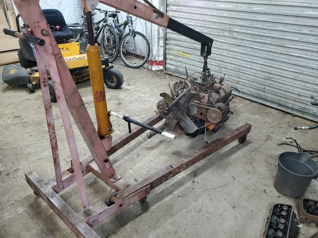 Powerplant with the crane staged by the garage door for transport to the build site. 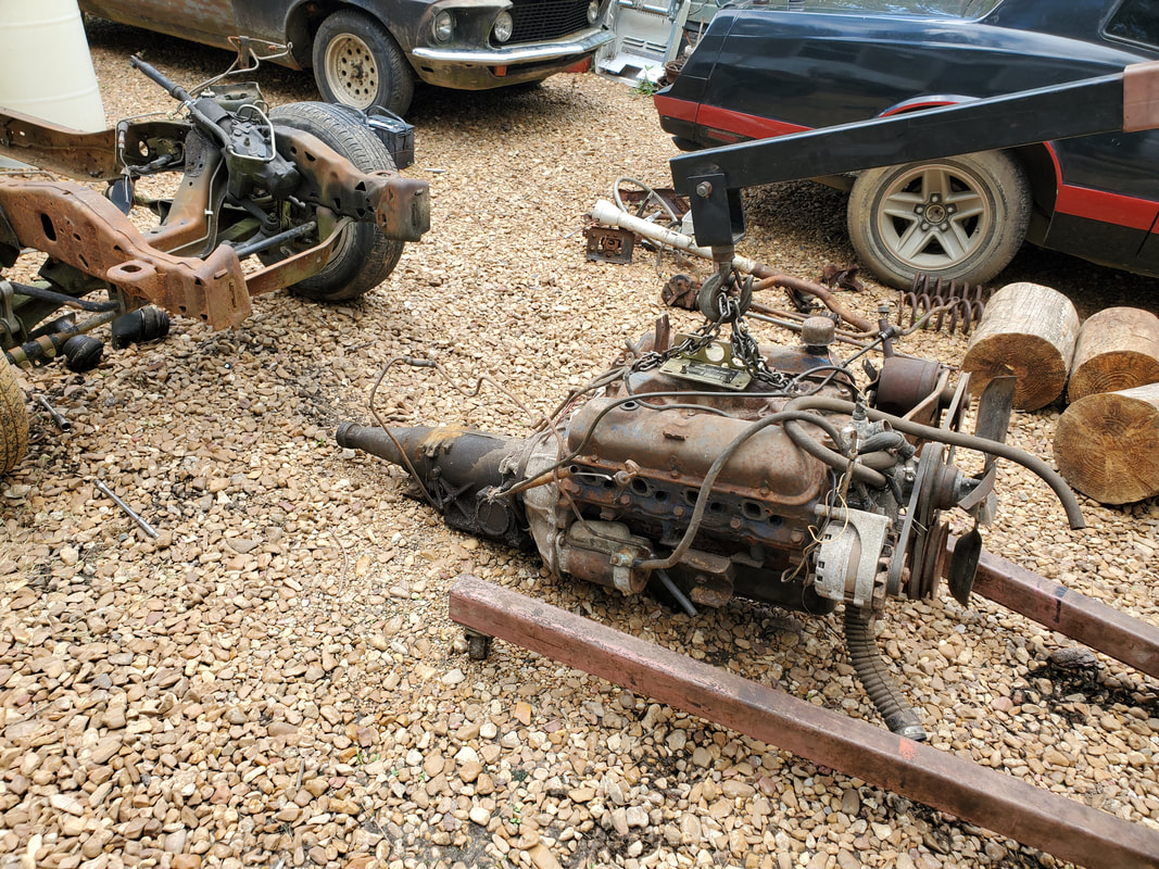 Engine with the crane staged in front of the Ranger frame at the build site. With the engine down at the build site, the real fun will begin. Besides removing the old engine mounts from the Ranger frame, there's the matter of verifying the engine fitting on the mount brackets and then figuring out how to get all this garbage secured. I can already see this being a pain in the ass...
For the longest time we've been rolling with a pair of aftermarket fans for the Scion. They've been doing a pretty decent job of cooling the engine down even with the AC running. There's a couple issues that are present with having fans mounted right on the radiator coils though. One, the fans have only a piece of rubber insulation between the fan body and the coil. Plus, a zip tie is routed through the fins of the coils to hold everything together. There's a lot of intimate contact with the coils of the radiator, with the wrong amount of vibration the only thing standing between normal operation and damaging the radiator. Second, without a shroud over the face of the radiator, we don't get the maximum cooling ability where all air is routed through the fans. Right now we have a lot of dead space around the outskirts of the fans where the only air moving through is natural air when the car is in motion. We're about to change that with an aftermarket fan/shroud assembly.
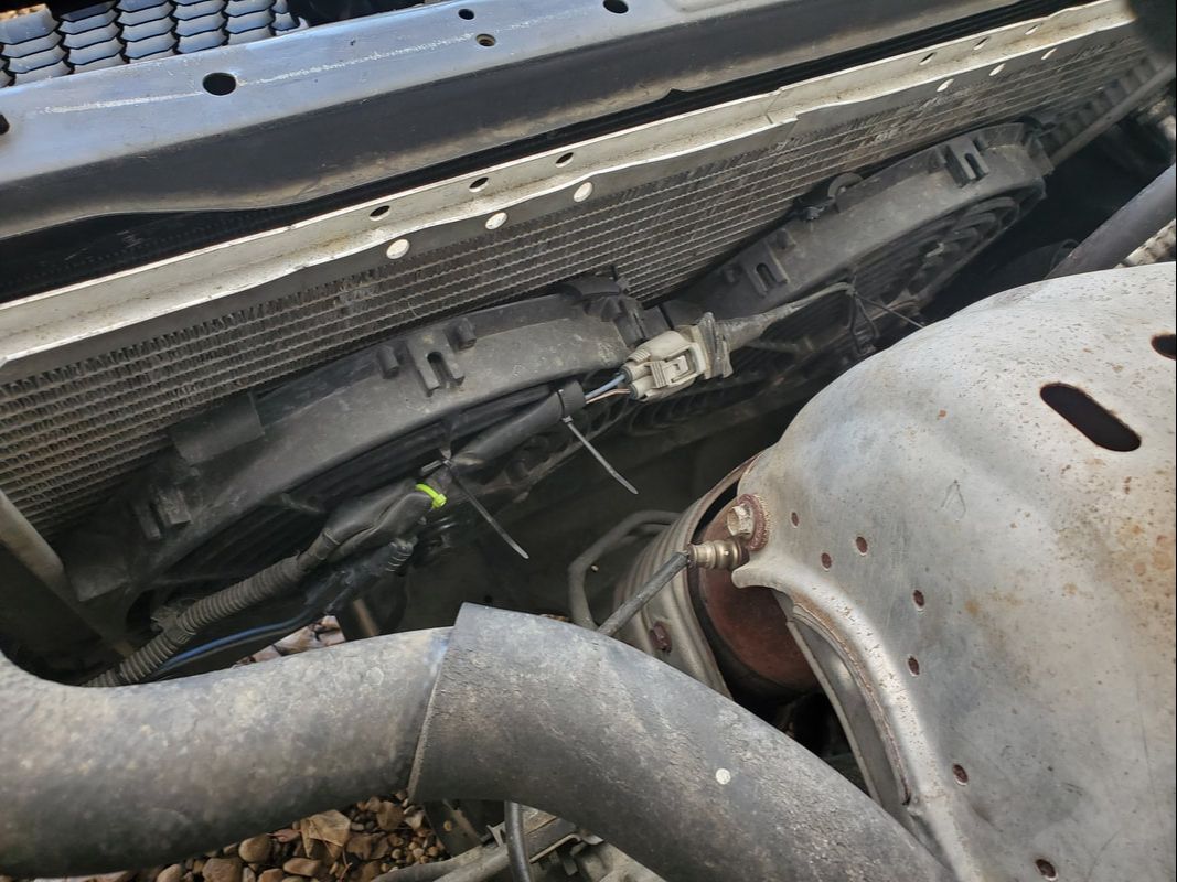
Aftermarket fans zip tied in place with rubber insulators on the stock radiator.
We picked up an assembly that incorporates the same generic electric fans that we were using before on the car, but with the added bonus of an aluminum shroud/face that bolts in place on the stock radiator. This is convenient as we don't have to use zip ties or any other fasteners to hold the unit in place. I will have to re-do the wire ends as I want to reuse the stock plugs from the old stock fans. That will just involve cutting the plugs from the old aftermarket fans and soldering them to the ends of the wires on the fan/shroud assembly. 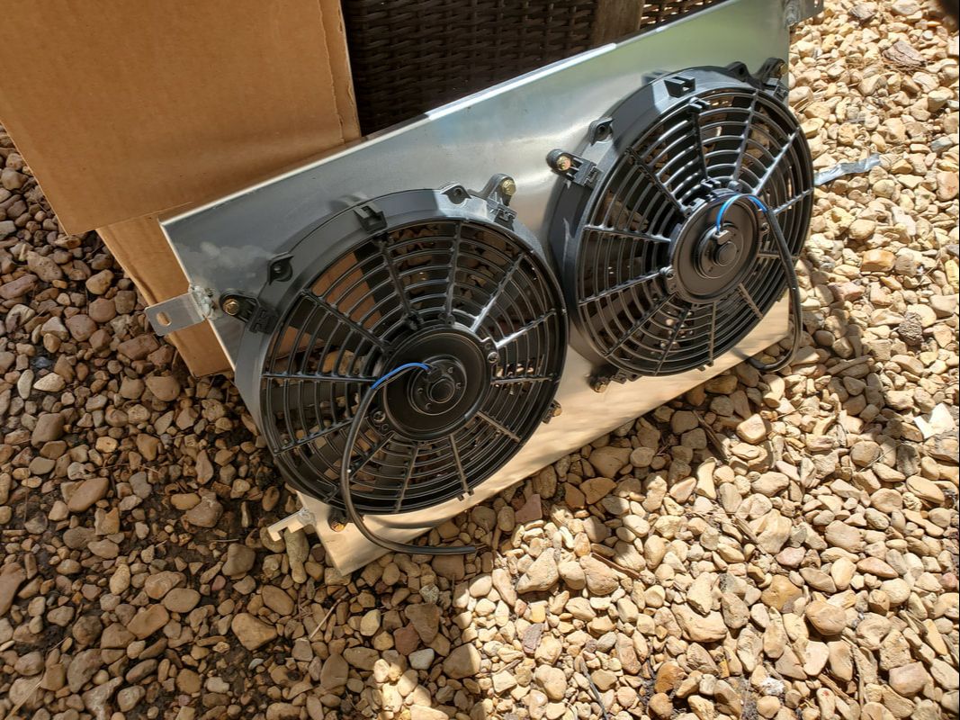
New aftermarket fan/shroud assembly. Uses the same fans as we have now, with the added bonus of an aluminum fan shroud.
First thing I had to do to make everything somewhat easy and less dangerous is pull the whole radiator out. Simple thing, drain the rad, pull the hoses, unplug the fans and pull the works out. Of course its never that simple, there's always little variables like the bullshit spring hose clamps or just the tight quarters that has one having to carefully snake their hands around to get to fasteners without damaging anything, hands included. 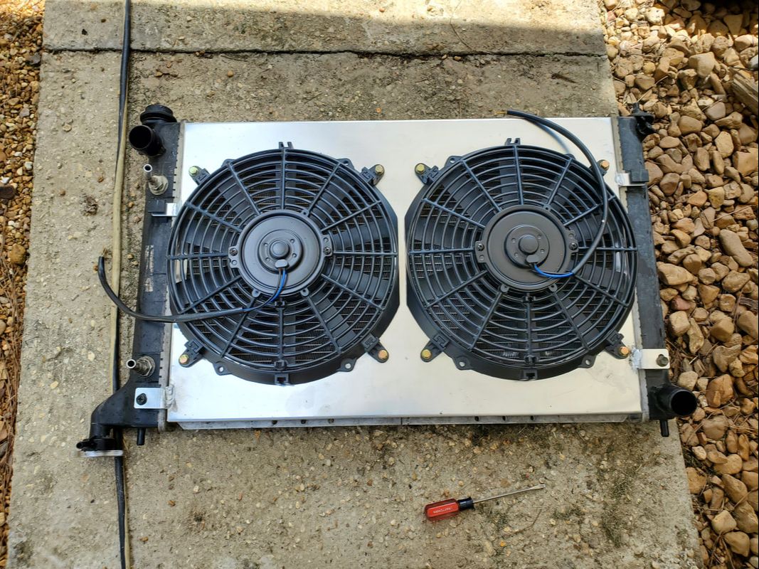
Fan/shroud assembly secured to radiator. Wires still need to be hooked up to the old plugs to finalize the setup.
As is always my MO with wiring, I soldered the ends together and used heat shrink tubing to cover the joints. The only exception was on one of the plugs where the plug did not have any wire on it, just the brass tabs in the plug. I removed the tabs and drilled holes in each one then soldered the wire ends to these tabs, then reinstalled them in the plug. The other plug was soldered and covered in heat shrink like normal. I carefully reinstalled the radiator in the car, got everything hooked up then filled the rad with coolant, leaving the cap off while running the engine to allow the system to burp some of the air out. 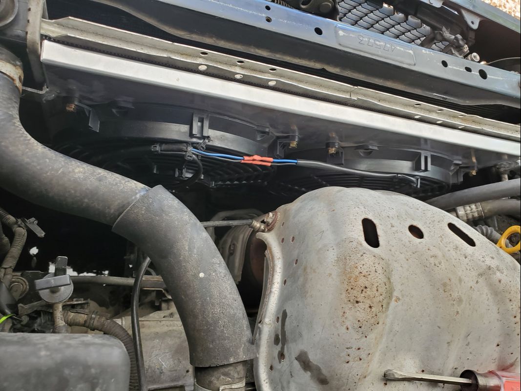
Fan/shroud and radiator installed in car with wiring hooked up, ready to go.
The car got up to operating temperature like normal, even with the AC on, and held just fine, even with the cap off. I put the cap back on and let it run some more, knowing the coolant is circulating through the system. Everything seems good so I buttoned up everything, calling this little job done. Good thing, the old fans I pulled off are the same as the ones on the fan/shroud, so whenever one of those fans dies, I have replacements ready to go easily. I'll just have to swap the ends again. Hopefully this will be the last time I have to play with this car for a minute.
I had a change of plan regarding how the timeline will go with the truck frame and the engine. Instead of bringing the frame up to the garage to install the powerplant, I plan on bringing the powerplant and the engine crane down to the build site and install it in the frame there. Of course this also means moving the frame to the spot and staging it under the car body. This has a twofold benefit as I get to do some preliminary fitting of the body to the frame, even before putting the powerplant in place. First thing of course was moving the frame into position. 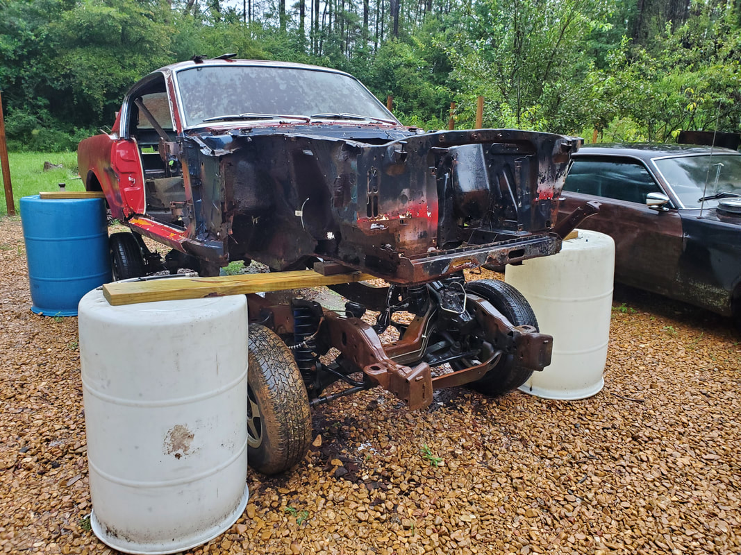 The truck frame mounted under the car body. Note the extra 2x4's under the front board holding the front of the body slightly higher. I had to move the F250 out of the way to allow me to move the frame out from its old resting spot and stage it in the Midway. To kill two birds with one stone I used a tow strap to pull the truck frame out as I moved the F250 out of the way. Parking the F250 in the side path had the frame in the Midway where I wanted so we could angle the wheels and make our final approach towards the car body. Once we got the frame into position and lined up as best as possible, we started pushing the frame under the body, taking our time to watch everything as the frame made its way under the body. 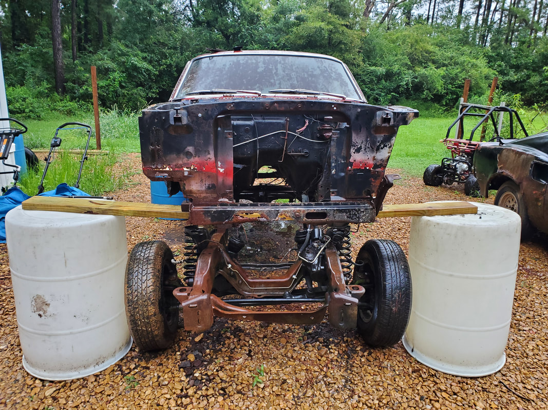 A frontal shot of the frame under the car body. We had to space the drums farther apart to clear the wheels of the frame as we rolled the frame in position. As the higher rear portion of the frame made its way under the body, it made contact with the lower point of the front subframes. The downward angle of the bottom of the subframes presented a problem. This was an instance where I wished I did lift the body high enough to position the board under this point on the subframes so this wouldn't be a problem. I ended up letting the air out of both rear tires to get the rear of the frame low enough to allow it to clear the bottoms of the front subframes and further roll the frame under the body. I even had to add a couple small 2x4 pieces on top of the front board to get the front of the body up just a little bit more to allow it to fully clear the truck frame at all the different points along the frame. We also had to space the front drums farther apart to clear the wheels of the frame as we rolled the frame into position. 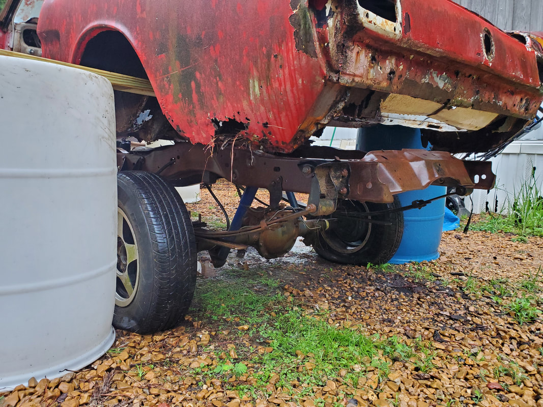 A shot of the rear of the frame relative to the rear of the body. Note how the length of the truck frame matches pretty good with the spacing of the body where I may not have to remove much if any metal from the ends of the frame. Looking at everything on the frame, I started making note of the parts of the unibody that will have to be cut out to allow for the kind of fitment I hope to achieve with the body on the frame. In order to clear the shock towers on the truck frame, I'll have to completely cut out the shock towers, lower control arm mount, and section of subframe just under the old shock towers so when the body is lowered, the truck shock towers will fit better. This will allow the front of the body to rest at a lower position so the car doesn't look like some ridiculous monster truck. 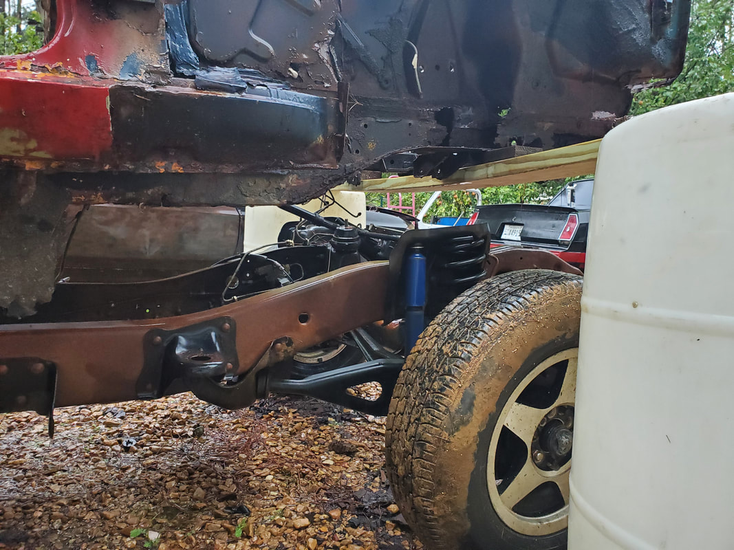 A shot of the truck frame shock tower as it lines up with the 65's old shock tower area. A lot of old metal will have to be cut out to allow for fitment of the body to the frame. As for the rear, I might actually be able to get away with retaining most of the rear subframes, as the upward angle of the 65's old subframes kind of aligns with the angles of the rear of the truck frame. Again, I don't want the body to be resting high on the truck frame where there will be excess clearance between the fender well and the top of the rear tires. I might find myself cutting out part of the subframes and adding flat stock iron to reinforce the remaining subframes as part of the placement on the truck frame. 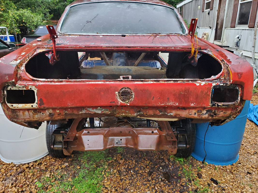 A rear shot of the body and frame as they sit in their staging positions. I will most likely have to add some flat stock on the front after cutting into the front subframes as well and add some metal around the side panels where the old shock towers would've been, in order to reinforce these side panels. Once the shock towers are cut out, all structural integrity in the front third of the body will be gone. I will have to relocate the front board and drums to a point more rear, as I lower the body down for final fitment. I will find myself adding a lot of aftermarket metal around the areas that get trimmed down so the body can stay rigid as its secured to the truck frame. There are six points on the truck frame that I noted for securing the body to the truck frame. 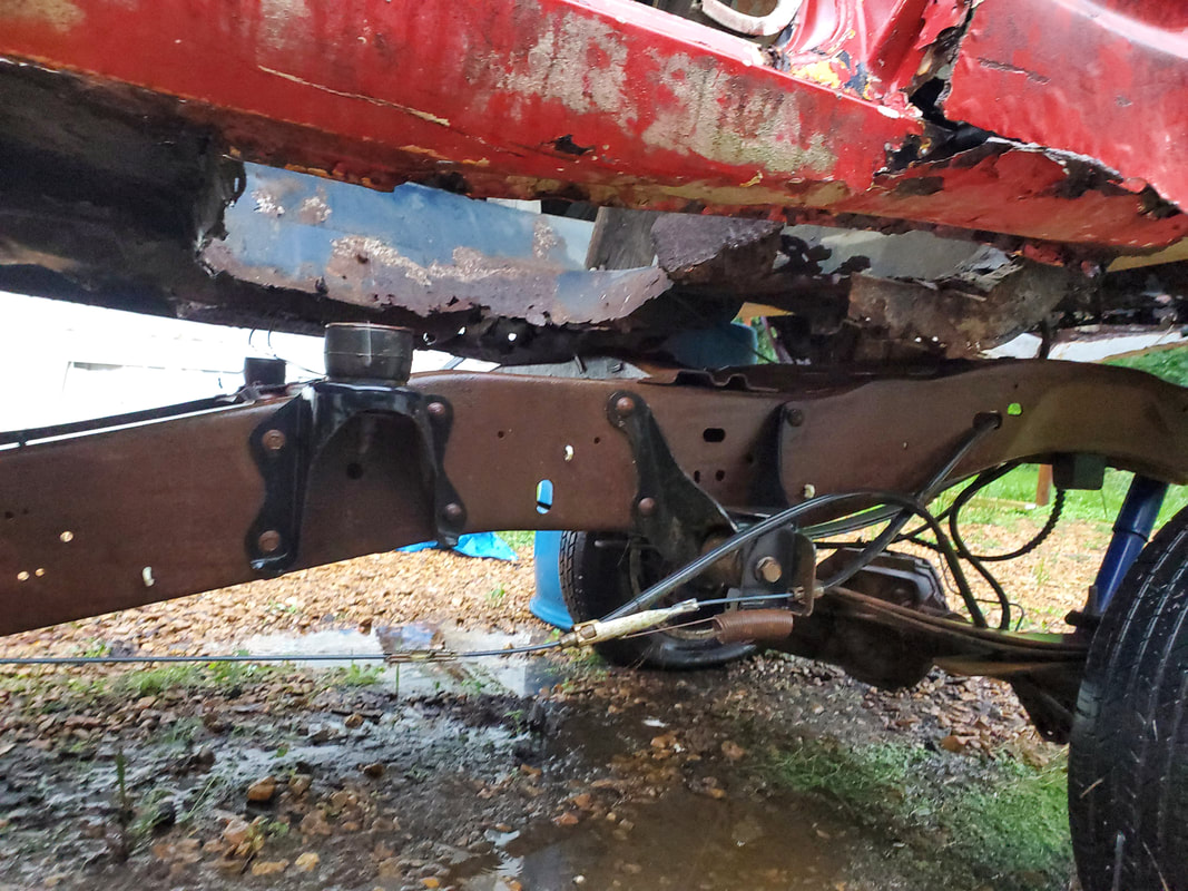 A shot of the middle of the frame and the area of the body where the torque box zones used to be. Also note the mounting point on the truck frame with the hockey puck bushing. 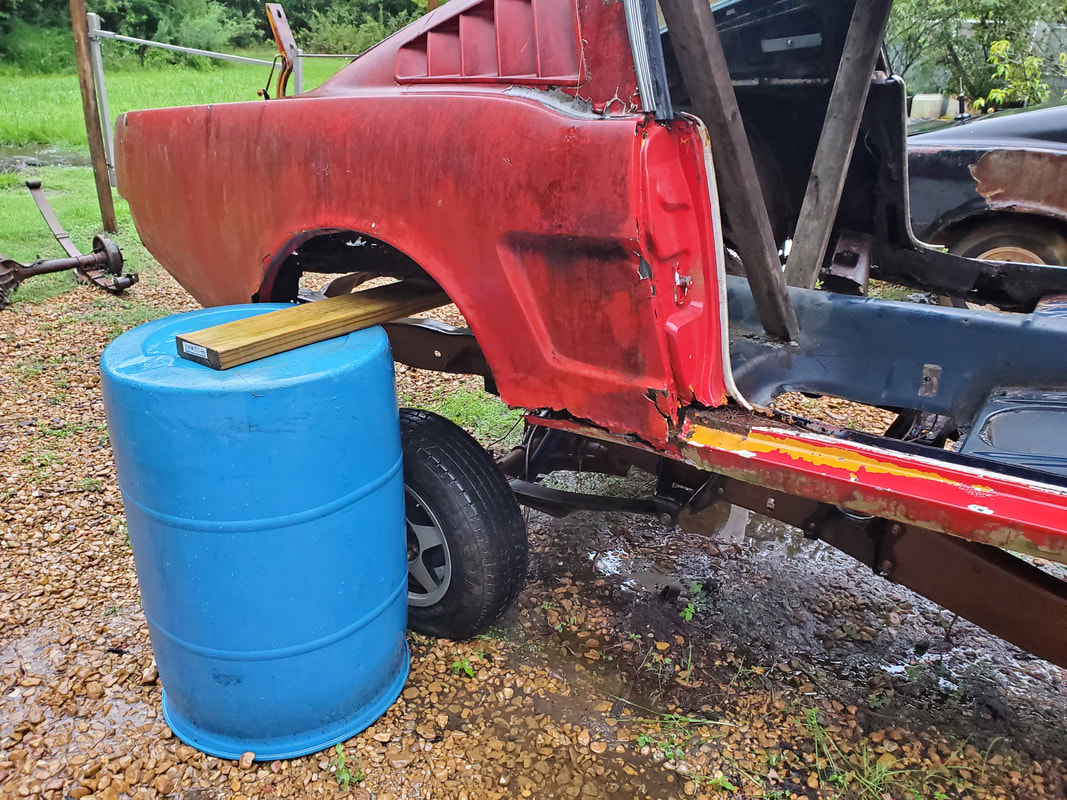 Another angle to the truck frame relative to the body. Note how the wheels line up with the rear quarters. Of course while I'm cutting out material to allow for the fitment of the body, I do still have to repair the floors in the cab area of the car. There is extreme rot in the cab area and all this will need to be patched and/or replaced. I do have some patch panels for the floors that I will be able to use, but I will also end up having to use some of the scrap stock to further patch the floors. Of course in the process of patching the floors, I will also have to add some angle iron reinforcements to the inner rocker panel areas prior to adding the new floor pans and sheet metal. I need to make sure that all the metal that is needed is added strategically so the body is as sturdy as possible and as solidly mounted as possible. This vehicle will have to be able to withstand the normal twists and bounces of normal road driving, as well as the flexing that a solid frame will do when rolling over varying terrain. 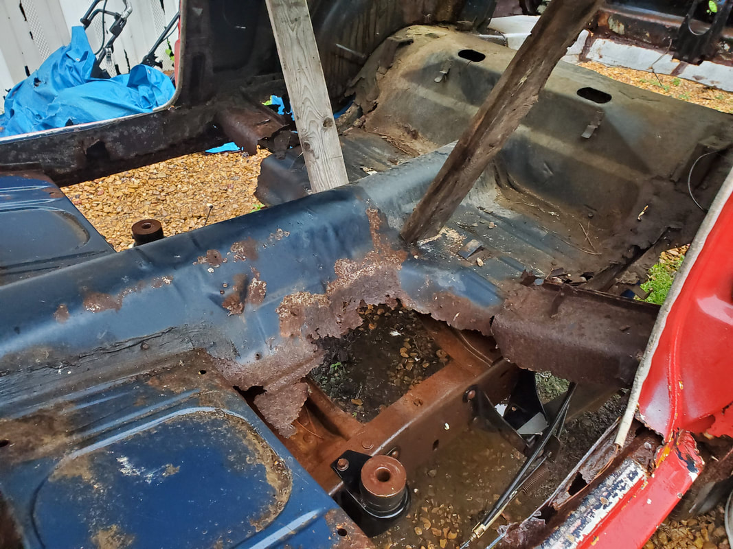 Inside of the cab showing the rotted and cut out floor areas that will need replacing as well a reinforcing to facilitate the mounting of the body to the frame. Note the mounting point of the frame. Also, in the process of fitting the body to the frame, I will have to temporarily fit the front fenders to the body to ensure proper ride height and placement of the frame relative to the body. One of my plans after the body placement will involve trying to put all of the front body panels together as a single unit. The fenders, grille panel, headlight bucket mounts (or whatever the hell these pieces are called) and front valance would all be held together. I'll probably have to add metal where needed to allow for these body parts to be held together. Once done, it will of course require two of us to lift the whole works up and set it on the front of the body, bolting things in place. I would add the front bumper last since there's no need to add even more weight to the whole assembly. Since most of these body panels are ratty anyway, any kind of modification that I do won't really matter. Of course my immediate plan will be to try and patch the panels like the fenders, since I'm not trying to spend hundreds on new body panels immediately. As time progresses I may replace this stuff but right now I just want to get the body fully on the frame and reassembled. With the engine crane in position, I was ready to lift the rear of the car body up. I started jacking the thing up slowly, paying attention to how the front was reacting as well as how the rear was acting. The rear valance panel did distort under the concentrated force of the boom pushing up into it, but with the chains, the body didn't shift. I kept slowly lifting the body higher and higher, until I got the back high enough to be able to slide the board under the rear subframe and onto the drums. 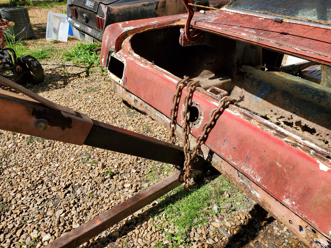 Chains wrapped around rear and valence panel and end of boom to hold body in place while lifting. With the rear now suspended on the board and drums, I moved the crane around to the front. At first, I chained the boom under the lower portion of the radiator support frame with the hope of having the maximum amount of lift. I also planned on putting the board and drums under the rearmost portion of the front subframe, where some past patches were placed. This point is lower than the rest of the subframe rails that extend to the front so I would have to be able to get the most lift I can get on the front end. 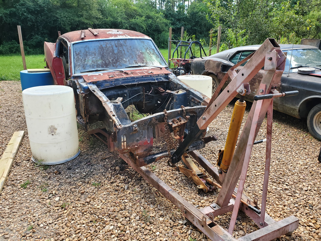 After getting the rear situated on the board and drums, the boom is chained to the lower portion of the radiator core support frame on the front of the body. Upon attempting to lift the front, besides the rear starting to shift backwards, the front of the boom eventually slipped off from under the frame support. I ended up having to move the boom to the top part of the radiator support, removing the hood latch assembly in the process. With the boom previously at around a 45 degree angle, lifting the boom had the effect of pushing backwards as well as upwards, resulting in the rear of the car body trying to push back. When I relocated the boom, I lessened this effect, but I still had to actually hold onto the front of the body, pulling forward as I lifted the crane boom to prevent the rear of the body from trying to slide back some more. I eventually got the front of the car lifted up high enough that the body was no longer horizontal, with the front end being higher than the rear. Looking at the front subframes, I figured I could put the board under the portion of the frame rail, just behind the lower control arm mount. This point was higher than the rear portion of the subframe, allowing me to lower the car body down onto the board and have it as close to horizontal as I could get it with the setup we're working with. This portion of the subframe was also still intact enough to hold under the weight of the overall unibody, despite the subframe rust under the shock towers. 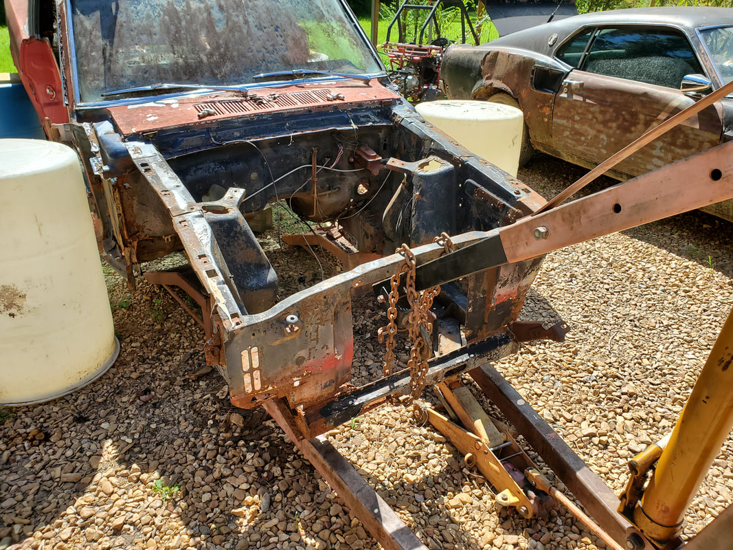 After a failed attempt to lift the front with the boom on the lower part of the core support, the boom was moved to the upper portion and chained back up. The hood latch had to be removed to allow for this arrangement. 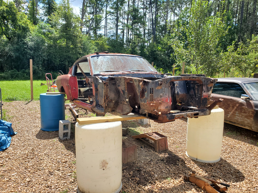 After carefully lifting the front up, I was able to get the board situated under the middle portion of the subframes, just behind the lower control arm mount, also getting the drums in position. I did have to move the engine crane back under the rear of the body to resituate the drums and board as one of the drums had a slight inward lean at the top. I wanted to get the drum back to as plumb as possible, making sure the board was on the strongest portion of the drum so it will hold and not cause the drum to distort enough that it could cause a problem later. After putting my hand on the body enough, it looked pretty sturdy, despite the overall sketchiness of the whole setup. The 2x6 boards have some bowing to them, but nothing so substantial that I should be concerned. I made sure the drums were spaced enough that the wheels of the truck frame will clear the drums when we roll the frame underneath. 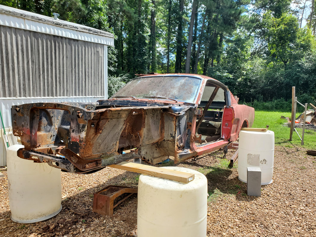 Another angle to the body situated on the boards and drums. 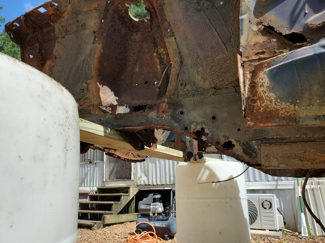 Closeup of the board on the subframe just behind the lower control arm mounts. The frame is pretty rotted but the overall support is still there with the shock towers and side panels. I did think about how I want to approach the next order of business on this build and figured after I get the oil pan replaced on the engine, we'll load up the whole powerplant and crane into the S10 and bring it down to the build site. We can get the truck frame partially staged under the car body on some preliminary fitting and get the powerplant on the ground in front of the frame. Installation will involve lifting the rig up and pulling the frame under the powerplant to lower it down and install it. This way we're not trying to drag the whole frame up to the garage as well as back down, with the powerplant in place. This way, with the powerplant already down at the build site, we can get most of the intricate work done, even while getting a sneak peak at how the body and frame will fit together with the powerplant in place. 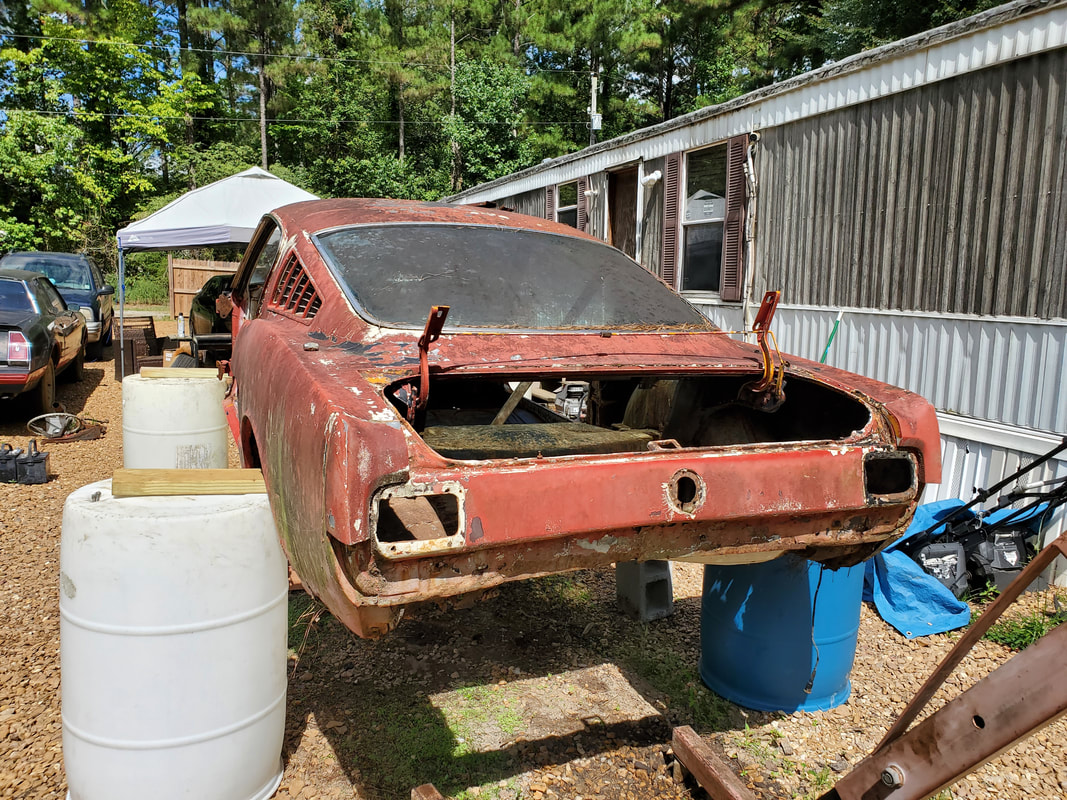 Rear of the body supported on the board and drums. Note the distortion on the valance panel just below the filler tube hole. 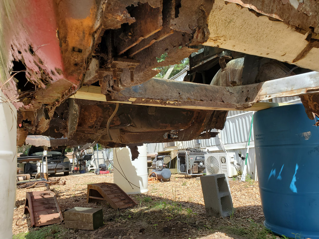 Closeup under the body showing where the board is situated on the rear subframe rails. The way things are going, this build is progressing rather fast. The body is already in the air, the powerplant is almost ready for installation, the frame has a set of tires, and all the unnecessary hardware is gone from the body. I will have to get some angle iron and other iron stock to use for building up the body in order to get it set up to mount it on the frame. I'll have to reinforce the body at the different points around the rocker panels and old torque boxes as well as the floors and subframes. Some material will be cut out and some will be added in order to get the body situated the way I need it to be when its fully secured to the frame. I want to have the right amount of lift on the body relative to the frame so the body doesn't look like some redneck monster truck vehicle with the body being too high relative to the running gear on the frame. There will be some lift but I will try not to have too much so this thing doesn't look too goofy. Either way, this build is moving along fast. With the body completely freed of any old running gear and setting on makeshift stands, the next order of business is to get the body lifted up enough to support it on the boards and drums I planned on using from the start. This will involve moving the engine crane into position, lowering the boom to a point where it will be under the body, in this case the rear of the body. My plan is to use some chain to help support the body while lifting it up with the top of the crane boom. I want to do the rear first since the ramps are better at supporting the car body at the extreme angle the body will be in when it's lifted up high to get the board and drums positioned under the back of the body. I'll end up probably using some fasteners to attach the board to the drums so nothing will shift or move when I start lifting the front of the car body up while it's on the board and drum at the rear. 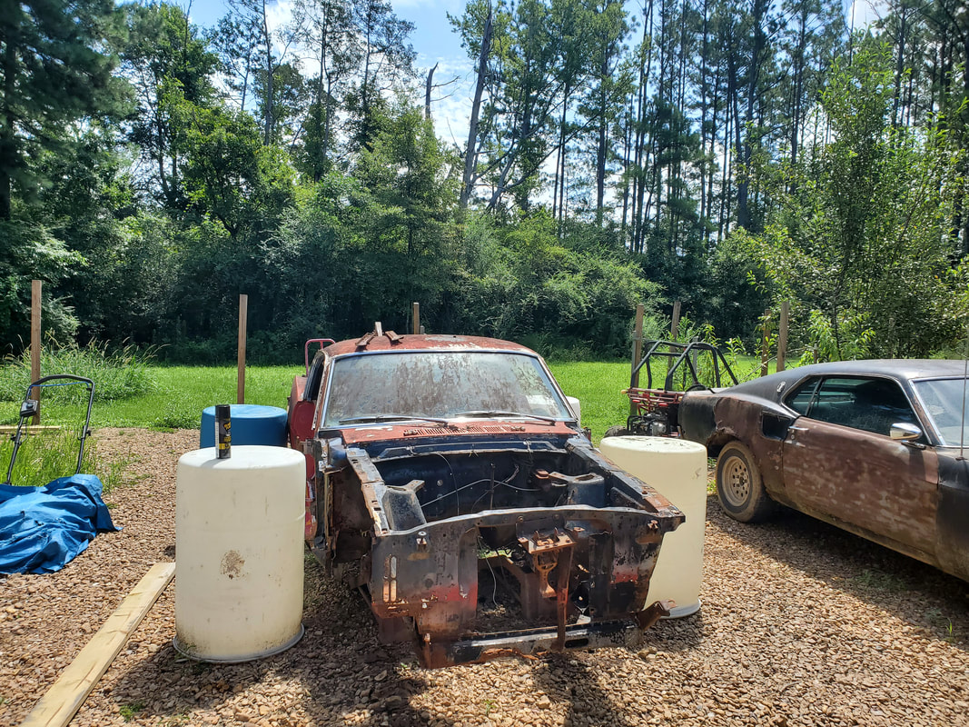 The four drums are in position where I plan on having them when the body is supported by the boards. 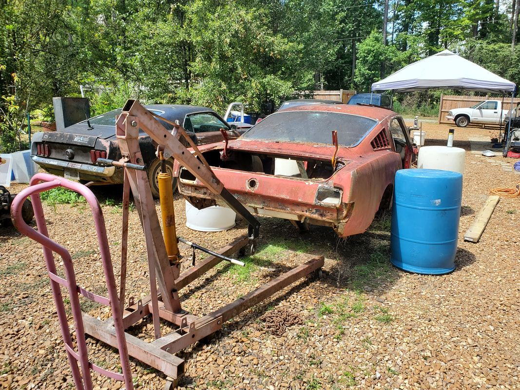 Engine crane in position behind the body with the boom placed underneath the rear of the body. With the crane in position I can get ready to start looking at how I will hook the crane boom to the rear of the body with a minimum risk of damage to the body panel. The same also goes for the front of the body with the core support. I don't want to damage any of this metal that I want to be able to reuse or otherwise not have to repair/replace due to distortion/damage during the lifting process. Once we get the body on the drums/boards, then the real work can begin. With the whole front end stripped down to the bare frames, the party moved to the back of the car. I already propped up the rear of the body on the 2x6 (not 2x8) board and masonry blocks so all I had to do is break free the spring shackles at the front and rear, which would drop the whole works down, and cut the parking brake cables and brake line, which would completely free the rear end from the body. There isn't as much discretion that needs to be exercised here since most of the stuff that needs to be disconnected is either rusted to hell or not needed either way so for all intents, I can just have fun chopping and cutting. 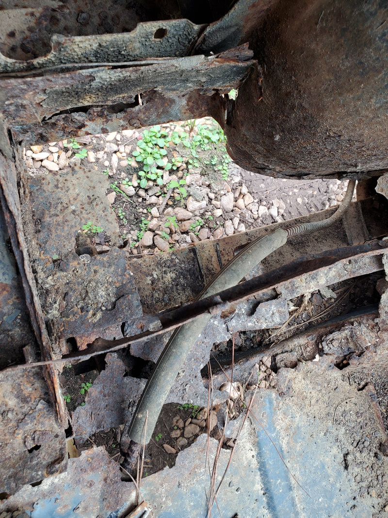 The right side torque box and spring mount, note the extreme rust around the area. There's not much material here to be cut out. 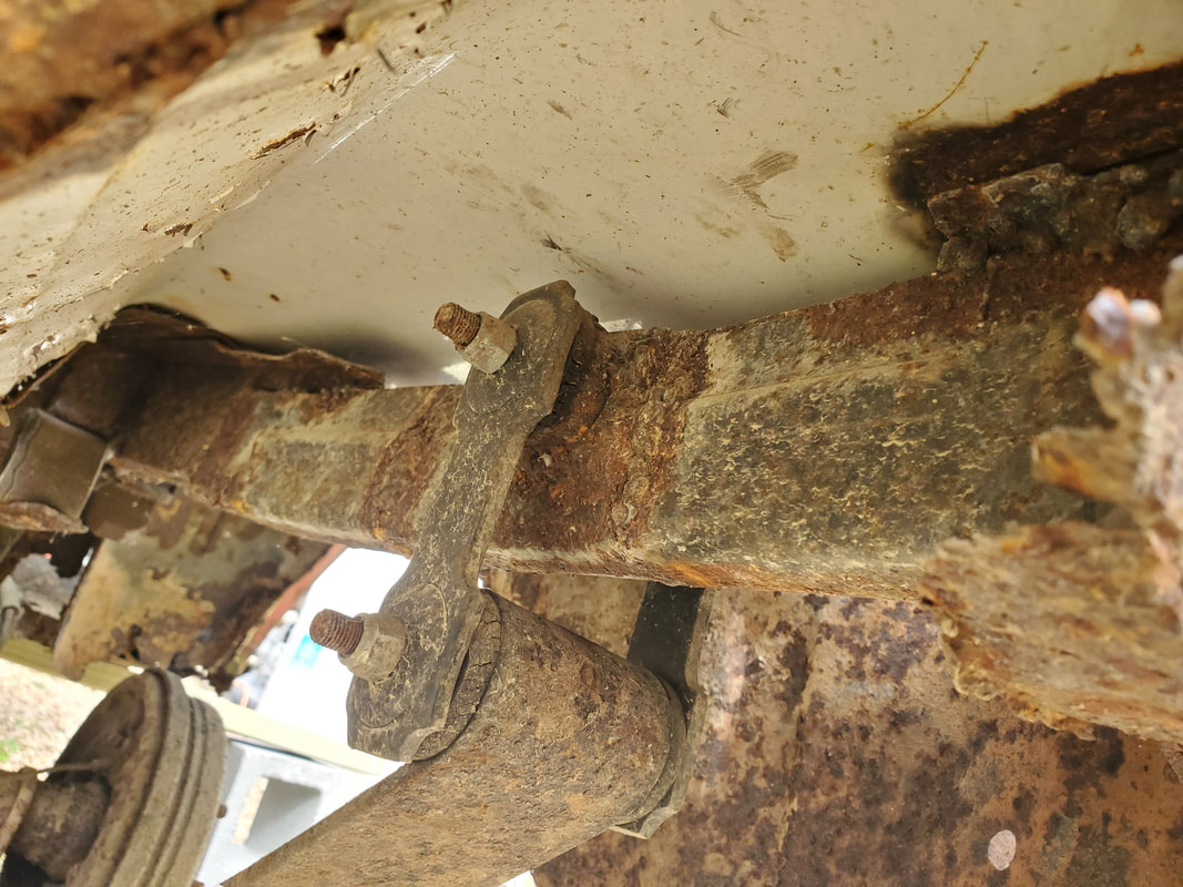 Rear spring shackle on the frame rail. This is pretty new, all things considered so this one should come out pretty easy. Starting at the rear, I removed the nuts on the right rear spring shackle. This was a pretty new install, as I had replaced this unit a few years back when I was just trying to fix the car up under normal circumstances. The old shackle was rusted to hell and needed replacing. The left side wasn't bad, so it was left alone. Unfortunately, the left side at this point was rusted all to hell. Removing that shackle involved cutting the studs within the shackles in order to remove the outer plate, then be able to remove the inner one that would originally hold the studs. Ironically the studs broke free from the inner plate so if I really wanted to, I could reuse the shackles, but they are so rusted out I wouldn't even trust trying to reuse them. The right side on the other hand, was able to be pried and tapped out intact so it can be reused. I should still have the other shackle as I bought these in a pair, so now the pair is reunited and able to be used later on in another car. 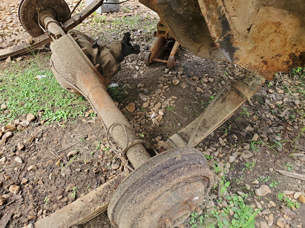 Rear spring mounts are freed up and the rear end is laying partially on the ground as a result. 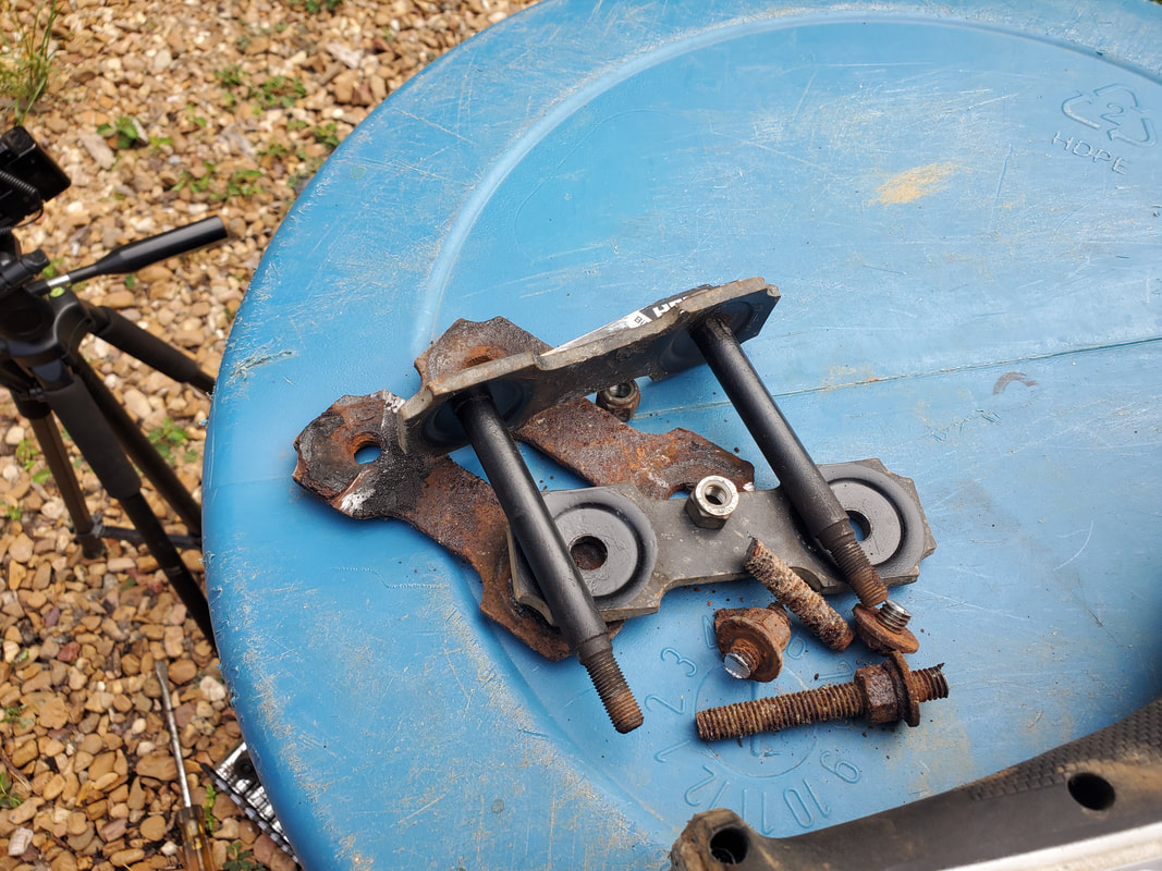 Spring shackles, both good and bad. Note the rusty plates of the bad shackle and the relatively intact good shackles. 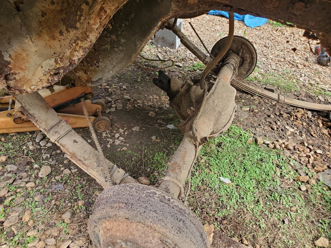 While I was at it I cut the parking brake cables and brake line to get them out of the way so when the front shackles are cut, the rear end will be completely free. With the rear shackles cut free and the parking brake cables, and brake line cut free, I moved on to the front shackles. Ironically the left torque box was rusted out more than enough that it was already freed up from the body. With that said and done, I moved to the right side. I had to cut a little extra metal out of the way and cut the stud on the inside and the one spot on the metal mount that held the spring to the torque box. After some grinding and sawing, I finally got the metal cut free, and a little hammering finished it off, making the whole works fall to the ground, free of the body. I dragged the rear end free from under the body and out of the way. 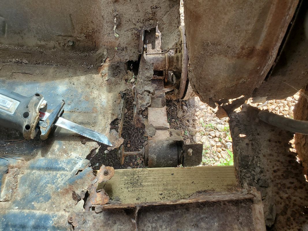 The left torque box, or what's left of it, showing how the front spring mount was already free from the body. 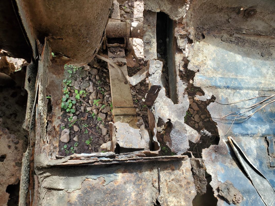 The right spring where it mounts to the torque box. Not much metal here to cut free to get the spring free from the body. 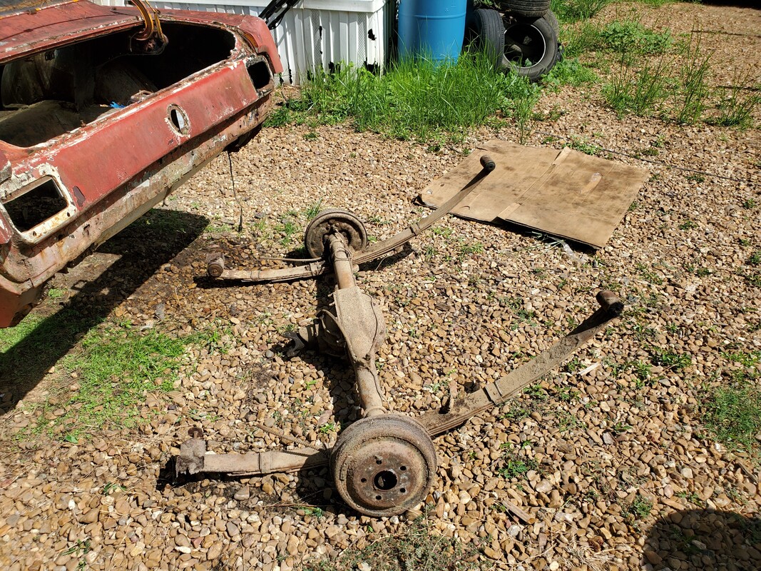 The complete rear end/spring assembly removed from under the body. With the rear end and leaf springs removed from under the car, the body is completely void of anything that is not needed at this point. The body is completely supported by the ramps and the makeshift sketchy stand setup. Even the rear is pretty light without the weight of the rear end in place. I'm still not going to attempt to just muscle the body up high enough to get it on the boards and drums, so the next order of business is to get the engine crane in position, along with some chain to lift up the back of the body as evenly as possible, enough so to get the board under the body at the right point to hold it up on the drums. I'll probably have to find some way to hold things together so when i jack up the front end, I don't have the body slide off the board and/or the drums. We'll get it done. With the front end completely broken down to the bare frames (what's left of them), the next order of business is the back of the car body. This is going to be tricky as all the lift points for a floor jack (rear end, spring shackles, leaf springs) will all be removed. That leaves the torque boxes (where the front of the leaf springs are bolted, or the edges of the torque boxes where they transition over to the rocker panels or the rear floor. That's all fine and dandy except for one problem - all this shit is rusted to complete dust. I had to come up with a creative yet crude way to lift the ass end of this body up with a minimum of further damage while allowing me to remove the weight of the rear end hardware. After an attempt at just trying to place masonry blocks under the rocker arm areas, which resulted in the ends of the rocker arms crushing dangerously, I had to come up with another creative way to do this sketchy shit. 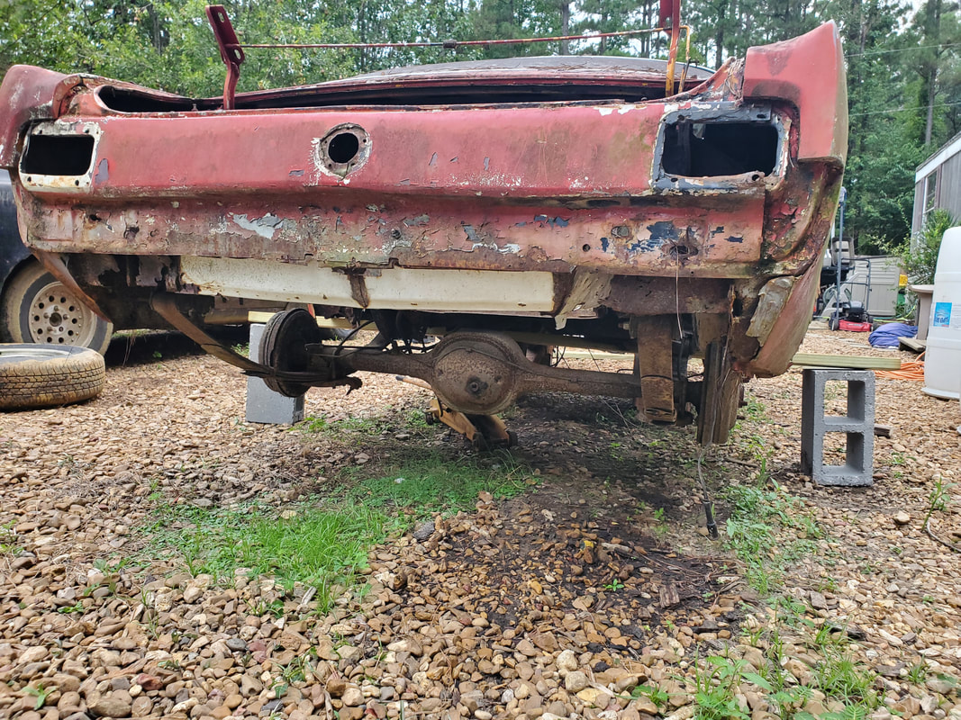 An underside shot showing how the 2x8 board is being used to hold up the rear of the body with a pair of masonry blocks. The wheels had to be removed before removing the jack as the body couldn't be lifted high enough to allow the rear end to just hang with the wheels in place. I ended up using one of the 2x8 boards that will later go between two drums as a support piece to take some of the weight by spreading it across the board and supporting it on the masonry blocks. It wasn't quite that easy though. The rocker arm areas would still try to crush under the downward force from the weight of the rear end on it. My solution to this problem: I cut a 2x4 into a couple long pieces that I propped on the rear floor just over the 2x8 and propped the top ends of the boards along the top of the door sill at the roof, using those points to take up some of the forces that are trying to further destroy the rest of the rear body of the car. After removing the rear wheels when I jacked up the rear end to get the back of the body off the ground, I lowered the rear end back down and as things settled, the forces transferred through everything. The 2x8 took up a lot of the force, warping under the weight and the 2x4's took a lot of weight, pushing up against the edges of the door sill and roof, keeping the middle of the body from imploding. 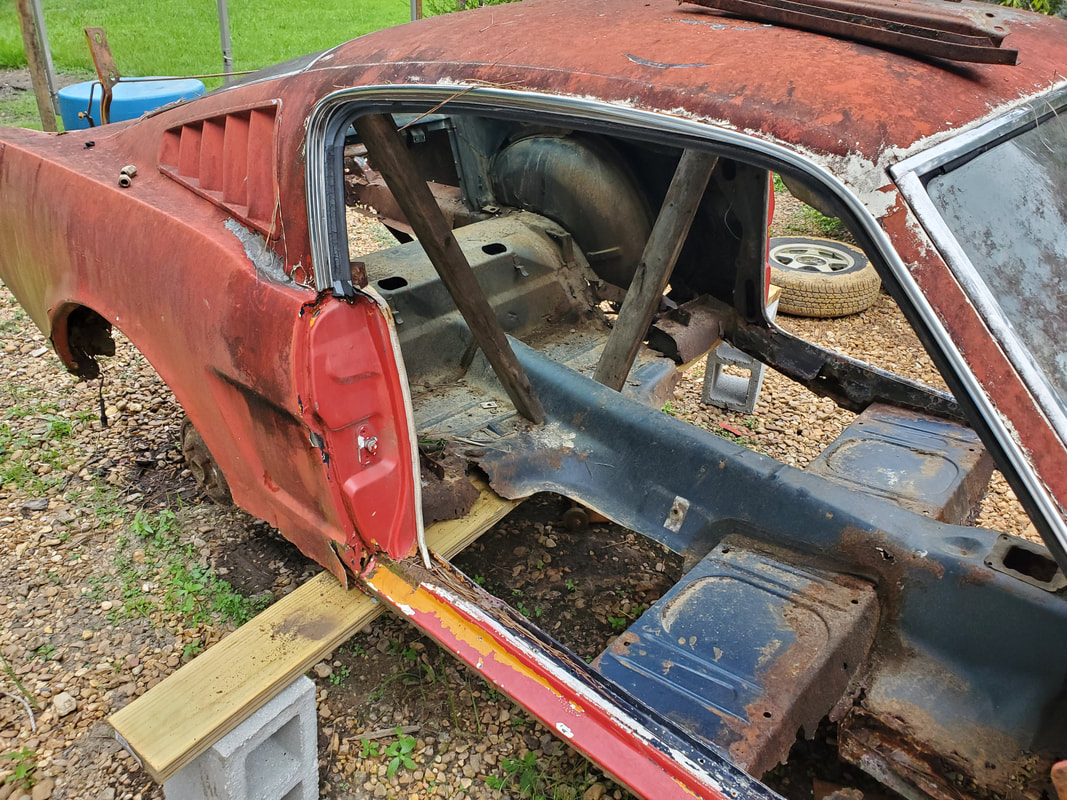 A shot of the 2x8 board showing how its supported on the masonry block along with the 2x4 boards inside to help maintain the rigidity of the body under these undue stresses on an already compromised body. Since I didn't want to leave the 2x8 under the warping force of holding the car body up, I ended up taking the floor jack and a piece of 8x8 wood chunk, placing the wood on top of the jack cup and jacking up the 2x8 as close to the middle as possible, removing as much of the warpage as possible for the time being until we can finish the removal of the hardware in the rear. 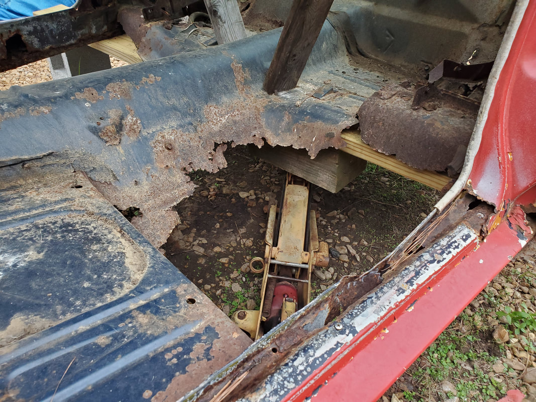 The floor jack with the chunk of 8x8 wood under the 2x8 support board to hold it up enough to take the warpage out of the board. I can imagine that when the rear end and leaf springs are gone from under the body, the rear will probably be pretty light just as well. We're not talking light enough for one man to lift up but light enough that the engine crane can do the job while being anchored to the body in a way where the already rusty body won't further disintegrate when I attempt to lift it up high to set it on the drums and boards. Once the car is on the drums, I can then shift my focus onto getting the powertrain mounted in the truck frame. I already am in the process of getting the powertrain ready by getting ready to install the intake manifold and the rear sump oil pan. I will have to add a different set of engine mounts to allow the V8 to set on the mounts of the Ranger, which according to research, is just a couple of fox body Mustang engine mounts. I still have to install the wheels pulled from the 65 onto the truck frame to allow for easy moving. Once the powerplant is in place I can then stage the frame and start the final approach for the frame to get it mounted with the body. This will be another monumental moment in the course of our project history as I'll have morphed a car body to a truck frame and get into the advance stages of getting another car rolling that hasn't been rolling in over 15 years. The time has finally come for us to start work on the first done from scratch truck frame swap project. We already have one vehicle that is a truck frame swap but it was done prior to our acquisition of the vehicle. That is the 46 Ford, which is on an S10 frame. Our project is going to be done from the dead start. Right now we're starting off with the stripped down body of the car. Everything that could be removed has been removed, short of the front suspension/steering and the rear end/springs. I'll have to remove all this hardware in order to get the body fully ready for the installation on the truck frame. The plan afterward will be to use the engine crane, and possibly our neighbors tractor, to lift the body up high enough to set it on the boards which will be rested between a pair of oil drums, front and back. This will position the body high enough to allow us to roll the frame under the car, especially with the powertrain installed, so we can then work on placing the body onto the frame. 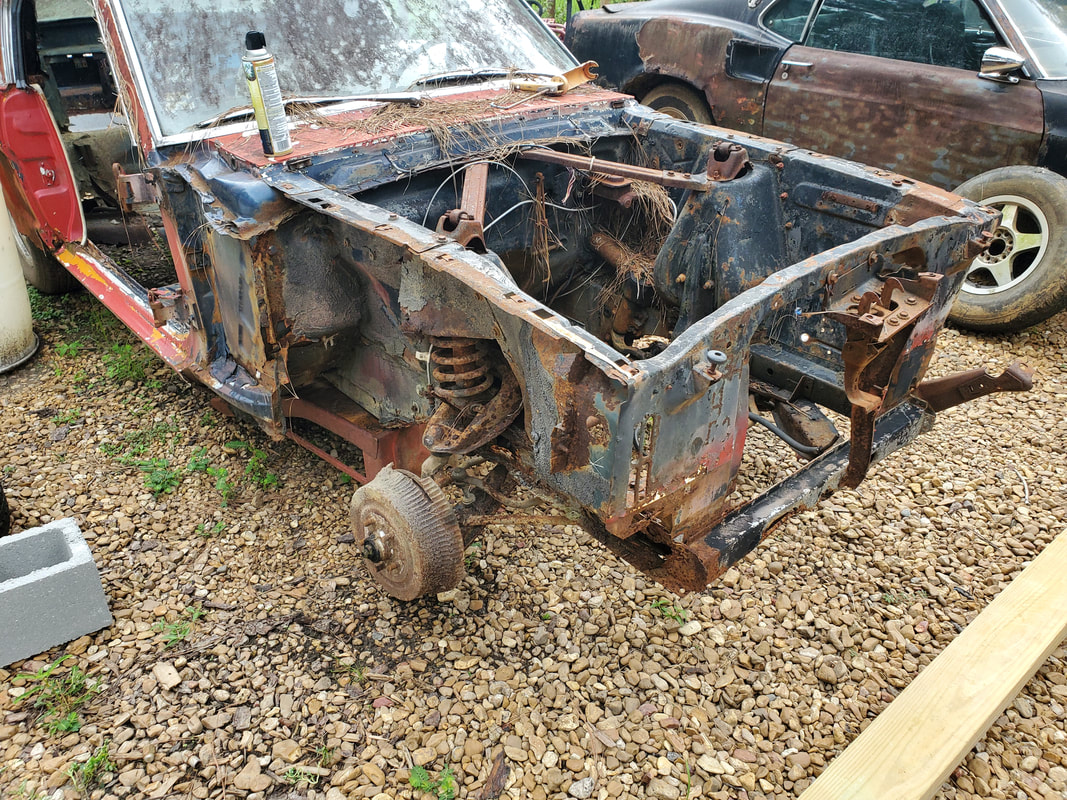 The Mustang body with the front subframes resting on ramps and the tires removed. 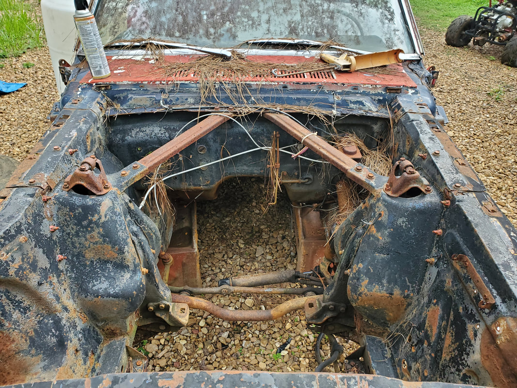 Shot into the transmission tunnel showing the ramps where they stand, holding up the front of the body. The first thing I did was jack up the car at the front end and place my set of ramps under the front subframes. I removed the front tires and rested the car on the ramps completely, freeing all tension/pressure on the suspension. After getting the car staged, I started on the right side removing the spring shield that is bolted up at the top of the shock tower. I had to cut the top of the shock where it mounts as well since the bolts at the bottom were rusted in place. I removed the cap that was holding the top of the shock. Next, I removed the two nuts holding the upper control arm, which in turn holds the coil spring. After hammering the bolts out, I used a crowbar to push the top of the coil out enough to make the whole works pop free. I had to remove the four bolts holding the upper ball joint to the upper control arm. From there I removed the upper arm, coil and shock. The upper arm/shock went to scrap, and the coil was saved as its still useable. The shock cap was also saved. 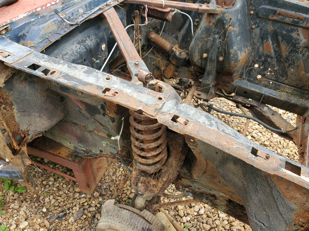 Shock tower/spring shield removed along with shock cap after cutting top of shocks. 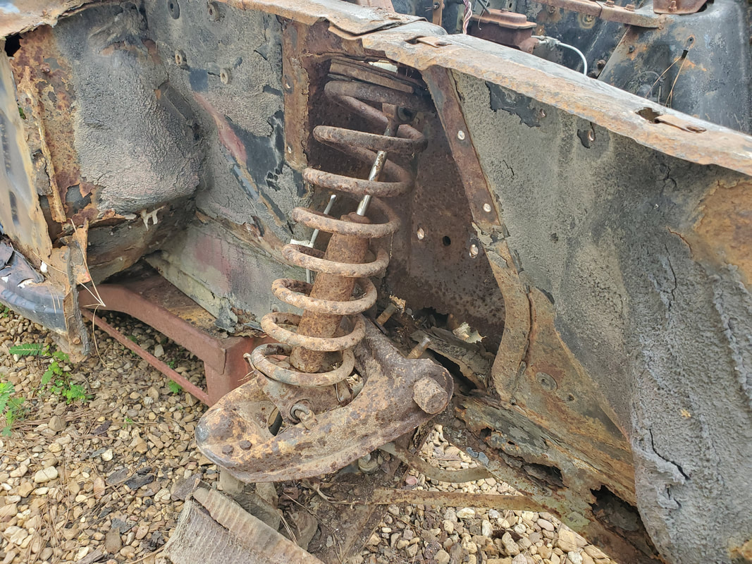 Upper control arm with coil spring popped free. 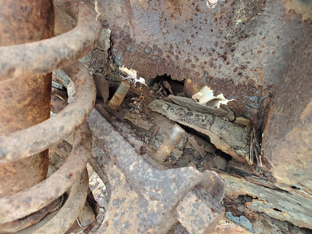 The extreme rust present on the frame rail around the bottom of the shock tower. Saving this would've been a near impossible undertaking that would've taken some serious time. With the upper suspension hardware free, I started work removing the other hardware. I popped the lower ball joint free and disconnected the brake line along with the tie rod end. Doing that freed the spindle assembly and got it out of the way. 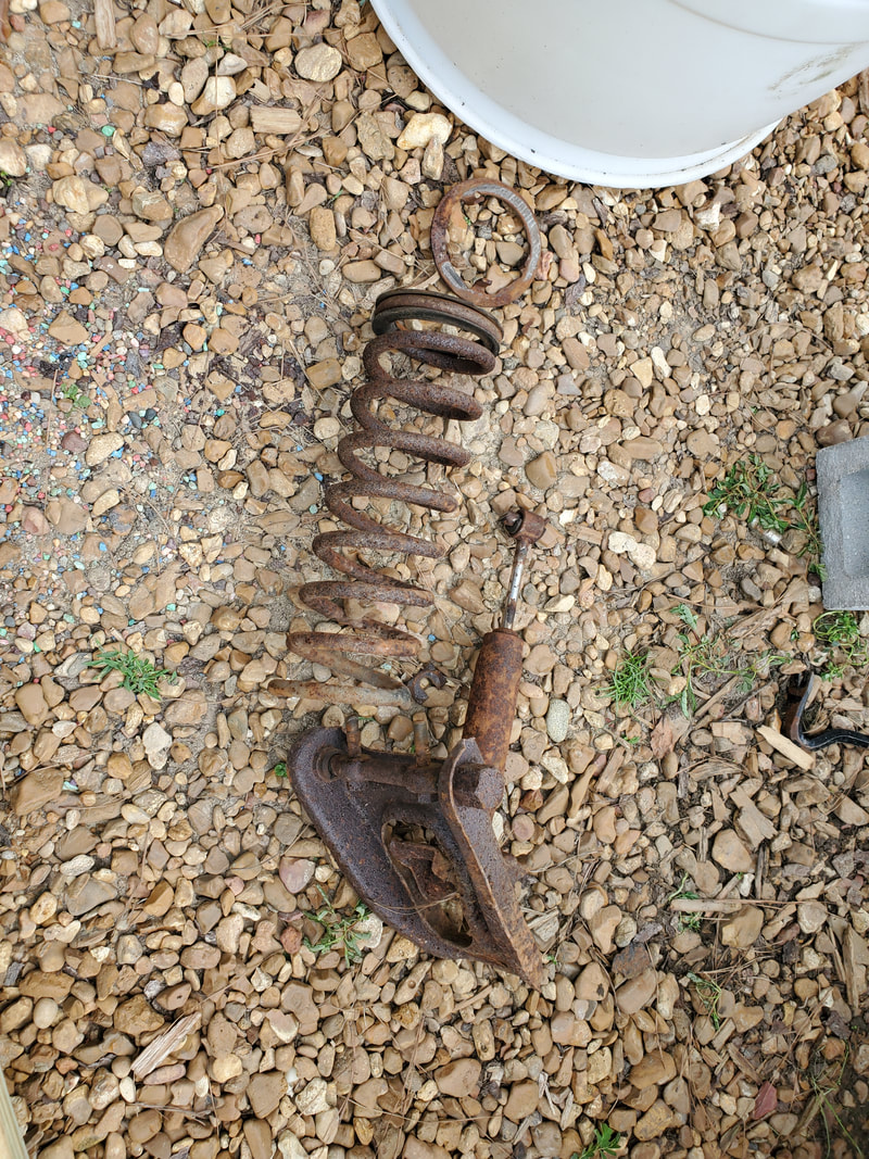 Upper control arm and coil spring removed from the right side. 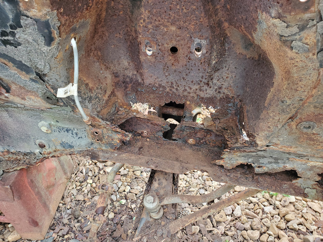 The extent to the rust damage is ridiculous around this area. After scraping and chipping away the brittle material, this is what was left of the area. 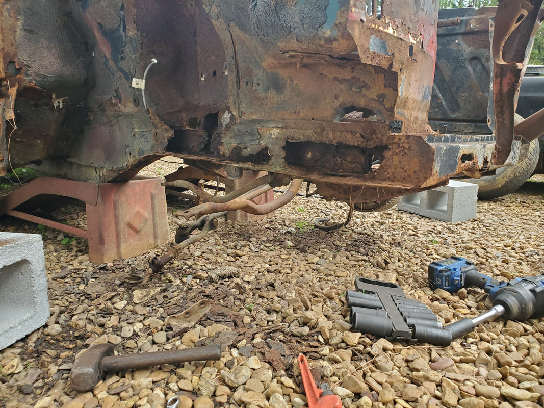 The rust extends out to the front of the frame rail. This is ugly. I continued down the line, removing the support struts on the top of the engine bay, then went back low to remove the mounts for the sway bars, control arm struts, and idler arm. I also pulled the bolt free for the V8 bar, which supports the subframes on V8 cars so nothing buckles or warps under the weight. The lower control arm came out as well, freeing everything up on the right side, from there, on to the left side to do the same thing. 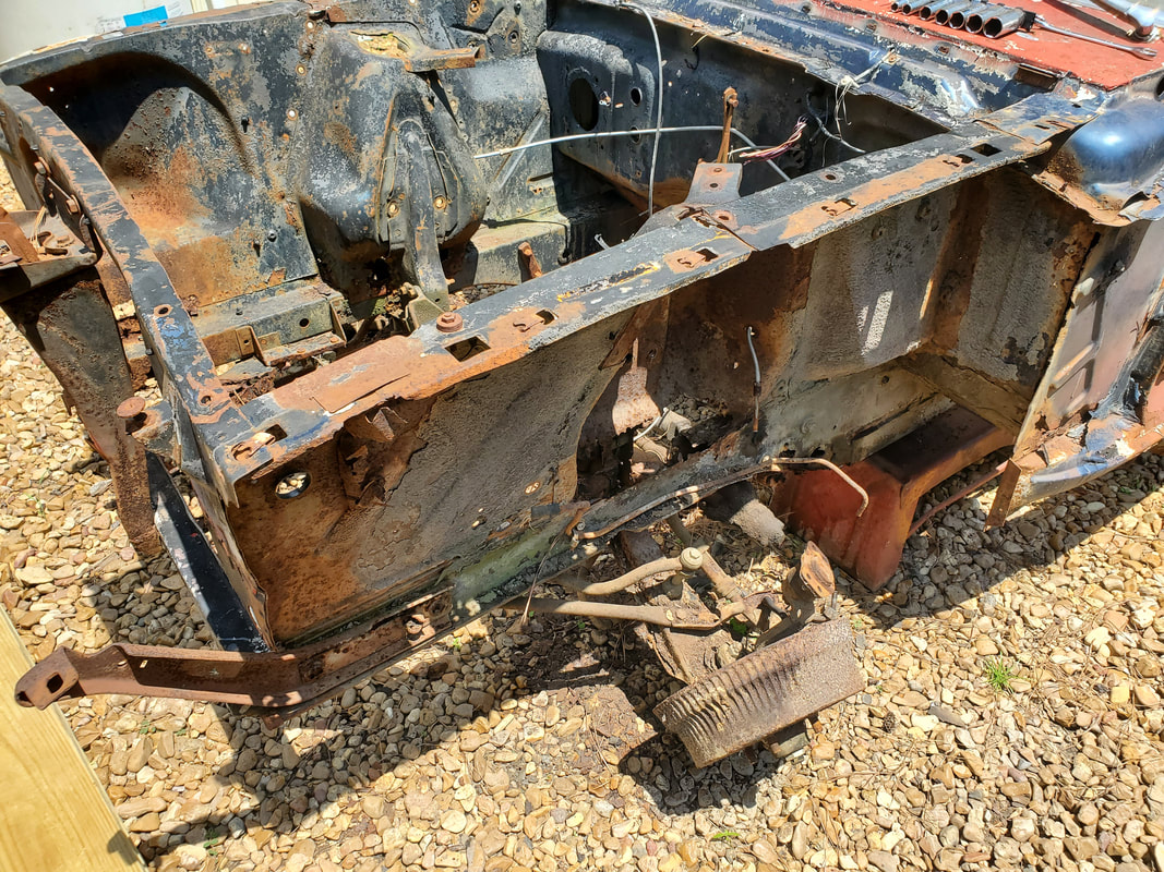 Right side upper control arm and coil spring are out. 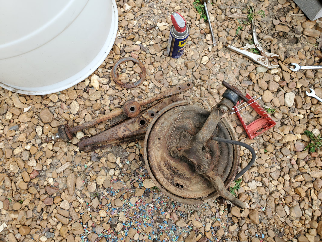 The drum brake spindle assembly, lower control arm and control arm strut removed from body. Now with the spindle and control arms out I finished up with the removal of the sway bar and V8 bar, and started the removal of the power steering piston assembly. Since a lot of these bolts were rusted to hell, I had to do a lot of grinding to remove everything completely. I probably critically damaged a part of the PS system, but this mess would need to be rebuilt anyway, if that's even a viable option anymore. I wouldn't have a clue if rebuild parts are available for these systems. Along with fighting multiple wasps that were taking residence in the left frame rail, I managed to get the PS assembly completely removed, along with everything else, leaving just the steering gearbox. 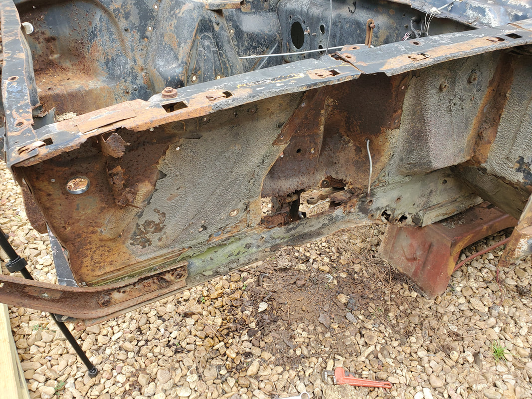 The frame section on this side isn't as bad as the right, but its still pretty bad. 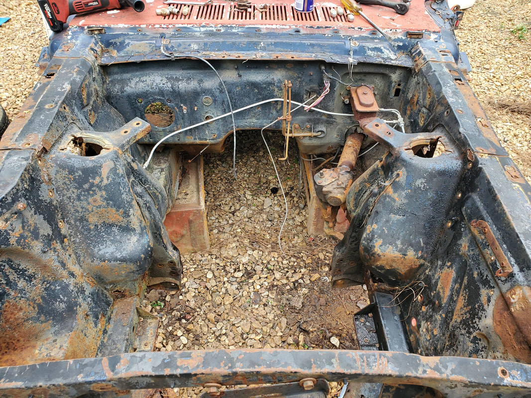 The engine bay sans all suspension/steering hardware, short of the gearbox. 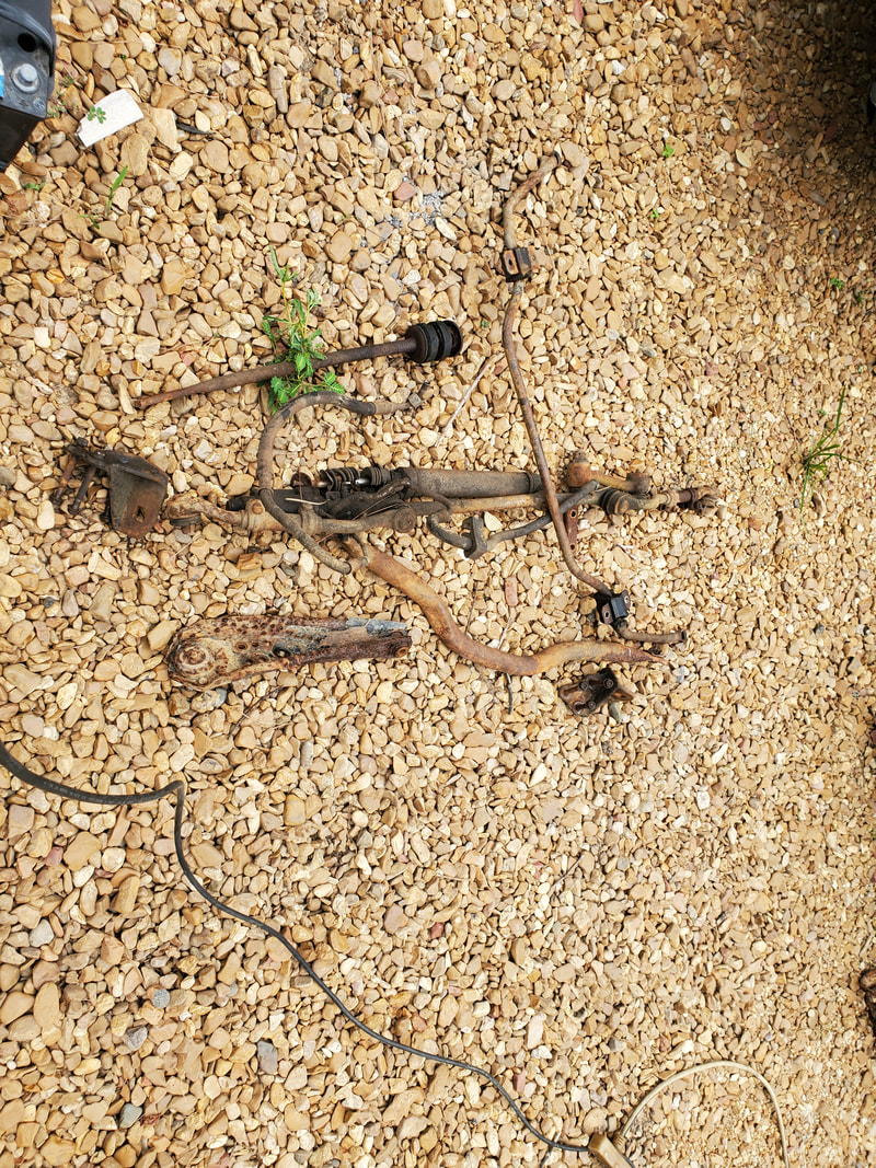 Power steering piston assembly and other hardware removed in the final stages of removing the steering/suspension hardware. Looking at the gearbox, I found that this assembly is not like later assemblies where a coupling of some sort holds the end of the steering shaft to the gearbox, facilitating an easy removal. This setup, involved removing the steering wheel from the inside end of the steering shaft, then pulling the whole steering column housing (which was already free) from the shaft, which was an integral part of the gearbox. Once the steering column housing was pulled free, I was able to remove the gearbox completely. This goofy design of the steering on this car has it where I will probably have to do some serious improvisation to be able to reuse the stock steering column tube and steering wheel. I will probably end up cutting the shaft at the gearbox, which will probably render the gearbox garbage, and weld some form of coupling to the end of the shaft in order to couple it to the Ranger steering gearbox. Either way, everything is now free from the front of the car. Surprisingly, the front of the car is pretty light, almost light enough for me to lift it up on my own. Two lifters could probably lift this thing up enough to place it on the drums, but we're not going to strain to do that. We will use the engine crane for this work. Work smart, not hard, or stupid. 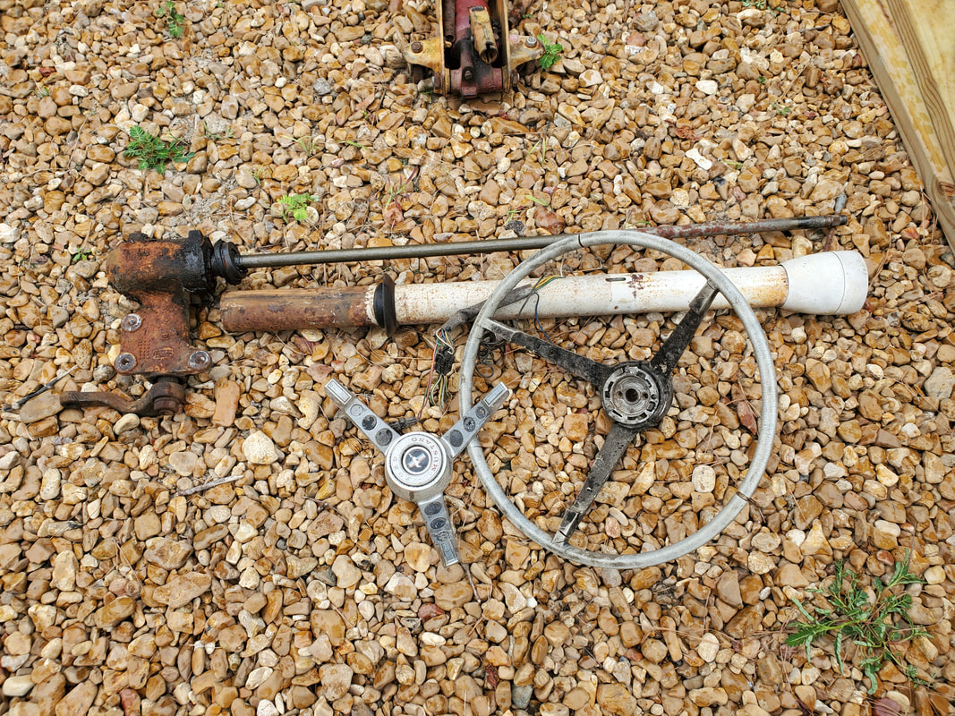 All the steering column hardware removed after further disassembly. This stuff is most likely going to be cut up and modified to adapt it to the new arrangement. With the front end done, we're off to a good start, the next order of business will be to get the rear end set up so I can remove the rear end assembly and leaf springs. Other hardware like the brake lines and parking brake cables will also have to come out, probably just get cut out since most of this stuff is trash anyway. The mounting points for the leaf springs will most likely get ground and cut out since most of the metal around these areas is rusted to hell so we're not really going to take a lot of time and care trying to remove this stuff from the body, most of the areas where the ends of the leaf springs are mounted will be patched or otherwise altered to facilitate mounting to the truck frame. |
