|
With a good amount of main work done on the main vehicles as well as other projects, like the Minivan Chicken Coop, I decided to take time to do some preparatory work on a couple Ford powerplants up in the garage. These setups are to be used for future projects that will soon be started in earnest in order to get a good head start on them before summer's end. One of the powerplants is the 289/C4 powerplant removed from the 65 Mustang during the initial teardown. This setup was rebuilt a long time ago and run a short time but never really pressed into service as the car was never finished enough. Now, with the dawn of the 65 Mustang Truck Frame Swap project on the horizon, its time for me to get the 289 powerplant prepped up to go into the Ranger truck frame so I can proceed to actually lifting the car body up to put the frame underneath. 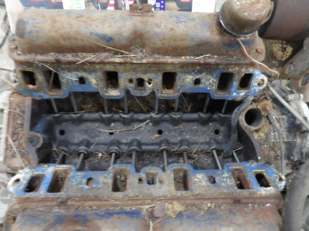 The 289 engine after removing the intake manifold for use on the 302 V8 that's currently in the FMT. A lot of dirt and trash found its way into the lifter valley. After removing the 4bbl intake from the engine to use it on the 302 that's currently in the FMT, the 289 ended up with a lot of trash in the lifter valley. I plan on installing the stock 2bbl intake from the same 302 that now has the 4bbl intake, onto the 289. I'll use a 2bbl carb, which was standard equipment on these engines with 2bbls, for the time being until I manage to source another 4bbl intake. I'm doing a lot of these projects with what I have available so rather than wait in order to spend extra, I can spend a little and use what I have available to get these things done sooner. I had to vacuum out the lifter valley on the 289, using a variety of vacuum attachments to allow me to get into the cracks and crevices to ensure I got all the dirt out from the intake ports and lifter valley on the engine. With the dirt and foreign matter gone, the engine is now ready for the intake, I just need more RTV gasket maker. 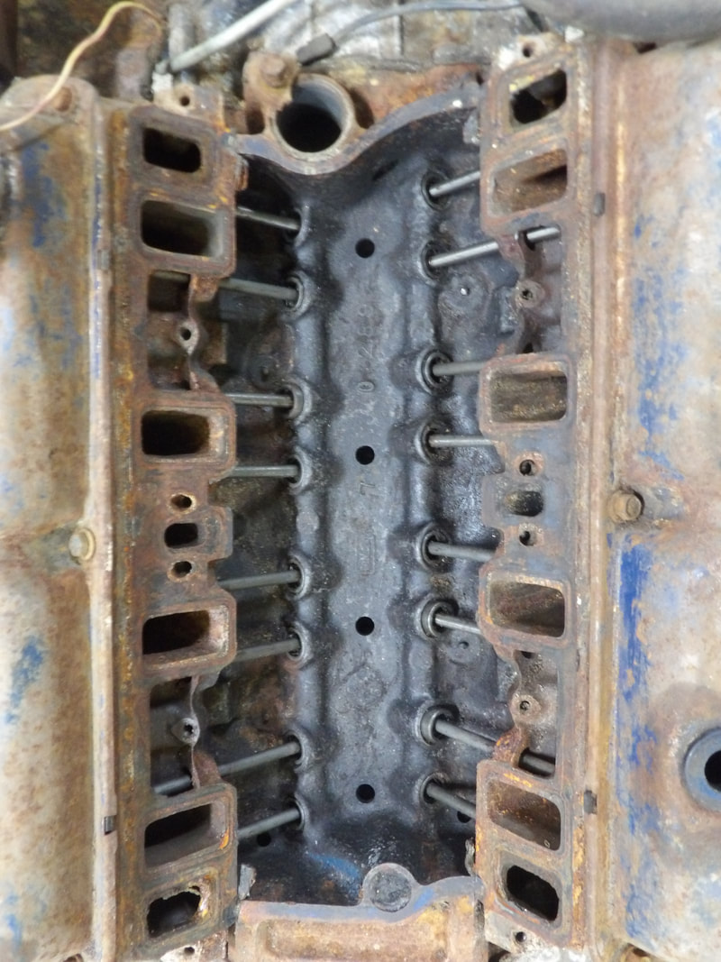 289 lifter valley and intake ports after vacuuming out the dirt and foreign matter. Before installing the intake I will take a minute to oil up the lifters and other hardware to ensure everything is nice and wet before I button everything up. I do have to jack up the engine in order to replace the front sump oil pan with a rear sump pan for its placement in the Ranger frame. Any oil I use for wetting everything down will obviously be disposed of, along with the dirt it takes with it, before the engine is completely buttoned up. The next engine that I had to play with was the 351/C6 I pulled from the 84 F150. This powerplant was sourced for use in the Rustang, the 69 Mustang that originally had a 351/FMX powerplant. The C6 is as close to the FMX as I can get, so this combination would be as close to factory as this car has had since I pulled the original hardware out. Unfortunately, I don't have a yoke for the C6 that has a narrow width U-joint, as the unit I do have came from the F150 with a larger driveshaft. There's a solution though, in the form of the C4 that was pulled from the 73 Mustang prior to converting it to a chicken coop. I will go out on a whim and say that this transmission is probably still good, as the biggest problem was the car just rotted out. I had the old driveshaft from the 73, which has the same wheelbase as the 65 or 69 Mustangs. I also have the flywheel from the 73 car's V8, which I'll need in order to use the C4. With that, I could use the C4, along with the driveshaft, to complete the whole package. Only thing I'll have to do is remove the C6 and its flywheel, which is warped anyway, and swap it out with the C4 and its associated hardware. 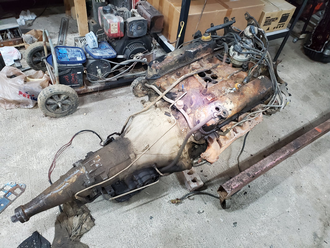 The 351W V8 and C6 transmission pulled from the 84 F150 truck for use in the Rustang. First thing to come off was the starter. I had to use a breaker bar and socket to rotate the engine in order to gain access to the torque converter bolts, four in total. Once that was done, I removed the oil lines from the C6. Once that was done, the six large bolts on the bellhousing were impact wrenched out quickly, allowing me to slide the transmission and its torque converter from the back of the engine. I slid the transmission aside and impact wrenched the six bolts to remove the flywheel, which is scrap anyway. 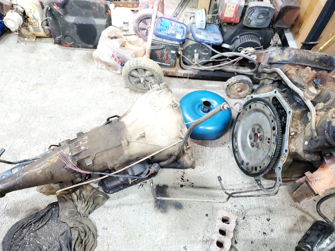 The C6 separated from the 351, with the torque converter slid out to make movement of the heavy transmission easier. As stated before, the C6's flywheel is warped, as I was having the hardest time with the starter engaging the teeth. It would grab at times and crank enough then other times would just skip over. Last time I experienced this, on the 69 Mustang in fact, the flywheel was warped. Anyway, the old flywheel was pulled and the old C4 flywheel was installed. With that, got things set up so I could put the transmission onto the back of the engine. 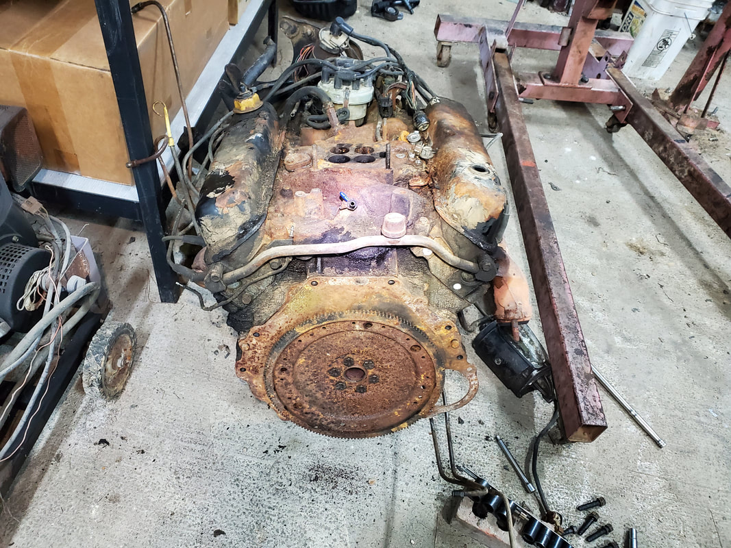 The old C4 flywheel installed on the back of the 351 engine, along with the bellhousing plate, which also had to be swapped out as the C6 and C4 plates were different. I installed the carb base plate and hooked the engine to the crane to lift it up a little bit, then positioned the transmission on blocks to try and get it at an angle that would allow me to work the bellhousing onto the engine. I seated the torque converter and after a little working, managed to get the transmission to slide home over the flywheel. The bellhousing bolts that were pulled from the C6 are about 1/2" too long, but I was able to get two bolts seated all the way as they passed through the legs on the back of the block. The other four are still sticking out 1/2" and will either need spacers or be replaced with shorter bolts. I installed the torque converter nuts to secure that part as well. With that, the C4 and 351 are pretty much mated. 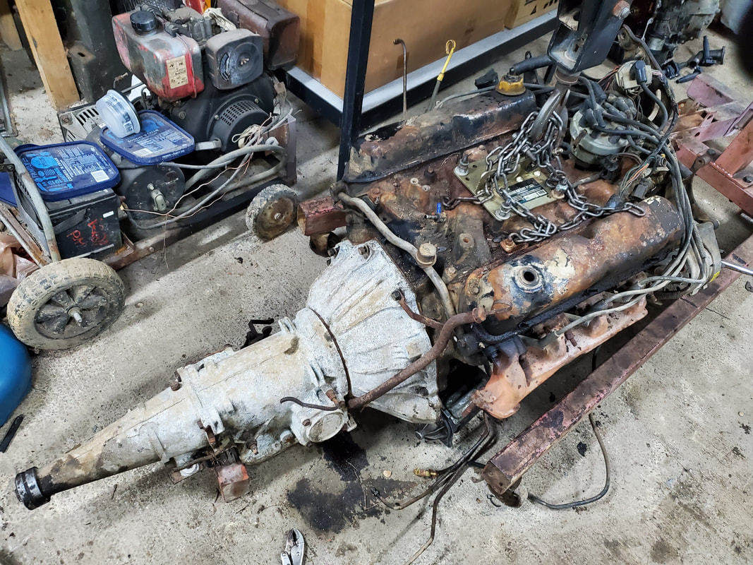 The C4 transmission from the 73 Mustang bolted to the 351 from the 84 F150. The next order of business is to get the other hardware on this engine. I still have to install the starter and transmission lines, and preferably a set of headers, so I don't have to use stock exhaust manifolds. When I went to put the starter on, I was blindsided by a broken bolt stud in the bellhousing. While this would deflate anyone's balloon, it means for me that I'll have to spend a moment with the sharpest drill bits I have and some oil and drill out this broken bolt/stud and use a longer bolt and nut to secure the starter in place. 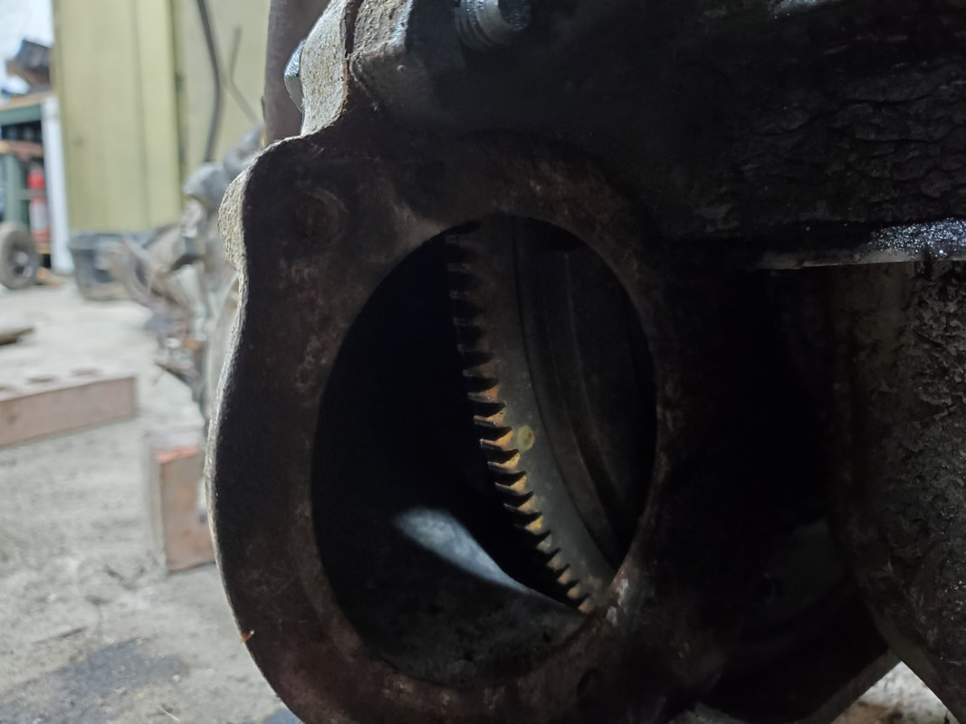 The top bolt for the starter is broken off in the bellhousing. The remnants will have to be drilled out. Once I get the starter bolt situation addressed, I have to remove the stumps of the transmission oil lines from the C4 then replace them with the old lines from the C6. I'll probably have to adjust the placement as the spacing of the oil lines on the C6 were a little more spaced out. No biggie, as I'll just have to manipulate the lines at the front of the engine in order to get everything to fit where I need it on the radiator. Maybe I'll have to cut and splice the oil lines at the radiator and bend the tubes to fit and flare the ends so things will fit somewhat like it did from the factory. But that will be for another time.
0 Comments
When one orders parts online to save a good buck, one has to accept the idea that there's a waiting period for those parts. This is ok when its a car that's just sitting around but when its a daily driver, this could be a problem. Luckily I had the S10 to fall back on, despite the idea that the AC decided to crap out by pissing all the refrigerant out. Luckily when I fully realized that there was a serious leak in the AC system, the replacement wheel bearings for the Tracker arrived. I only had one day to ride with no AC in the S10 before I got back to work on the Tracker.
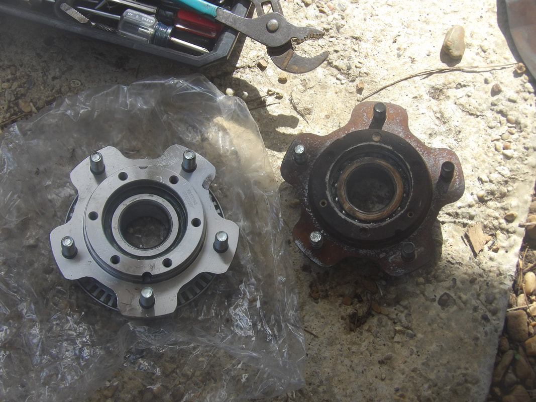
The new wheel bearing hub assembly next to the old unit.
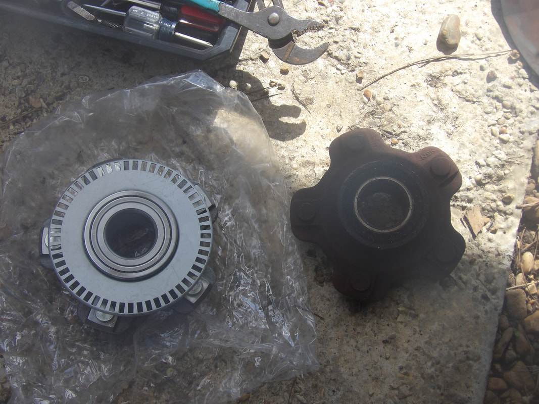
The new assembly has an encoder wheel built on the back of the unit for cars with wheel speed sensors. This part won't affect placement on our car.
The first thing I had to do was put the spindle and brake dust shield back in place, since they never needed to come off to begin with. After replacing those components, I greased up the axle and slid the wheel bearing assembly on. Since I only had two of the Phillips screws for holding the retaining washer onto the retaining nut, I only had to worry about lining up two bolt holes. Once the washers and retaining nut were in place and locked down, I was able to put the brake hardware back on. Things went pretty quick. 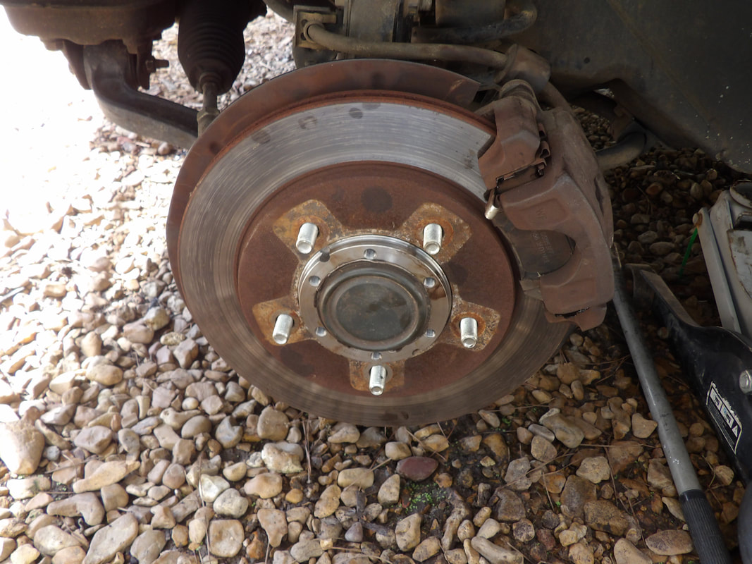
New wheel bearing hub assembly installed and brake hardware back in place on the driver's side.
With the wheel back in place, I moved my operation to the other side. After removing the wheel, brake hardware and the access cap from the hub assembly, I sprayed the retaining washer and Phillips screws with WD40. To my surprise the screws came off rather easily, making things go fast right from the start. 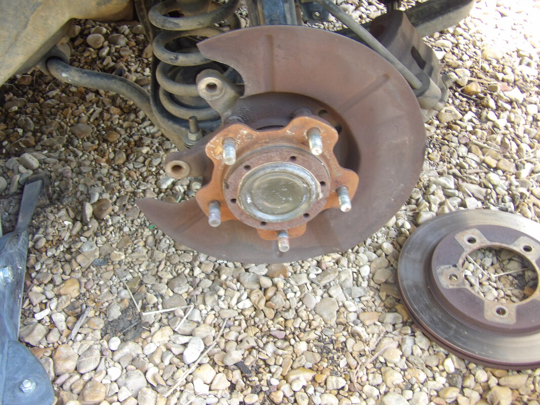
Passenger side hub assembly after breaking down brake hardware to expose the hub assembly.
After I pulled the retaining screws from the nut, everything came off super fast. The old bearing hub assembly slid off super fast. A little grease on the axle and the new hub assembly slid on. Retaining nut, washers, screws, everything went on super fast, secured. The brake hardware went back on super fast, completing the installation of the passenger side wheel bearing hub assembly. Once I knew what was up with these assemblies and how they go together, replacement was faster than changing brakes. 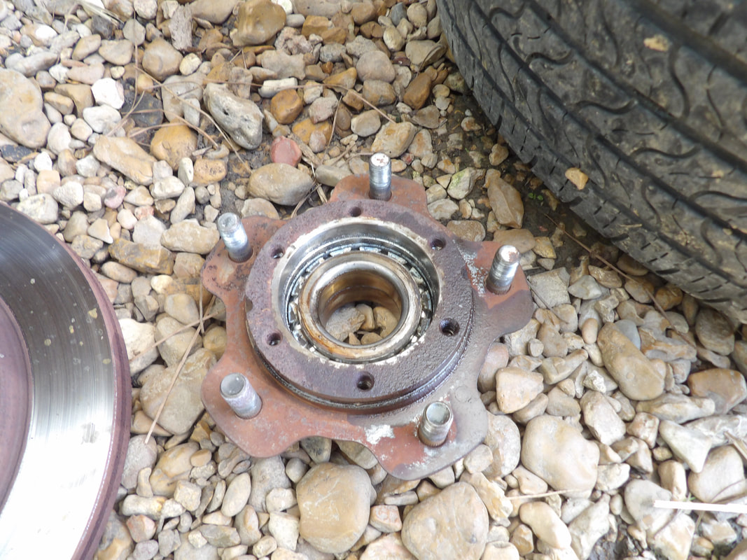
Old wheel bearing hub assembly removed from axle.
New hub assembly secured in place with access cap back in place over bearing.
Brake hardware installed back over the hub assembly.
With the wheel replaced I took the Tracker for a test drive. The car tracked to the right a bit for a little while until the driver's side brakes equalized to the passenger side. I had to compress the caliper piston to get it back on since the piston came out a tad bit while sitting. Once everything was even, the car tracked properly, even at highway speeds. With the Tracker's wheel bearings replaced as a set, I can ride easy knowing that this will not be a problem for a little while. I did hang on to the passenger side wheel hub assembly since it technically wasn't bad. Just in case one of the new assemblies does crap out, I can at least swap it out with our old assembly until replacements can be sourced. With that, I can move on to other planned projects around here.
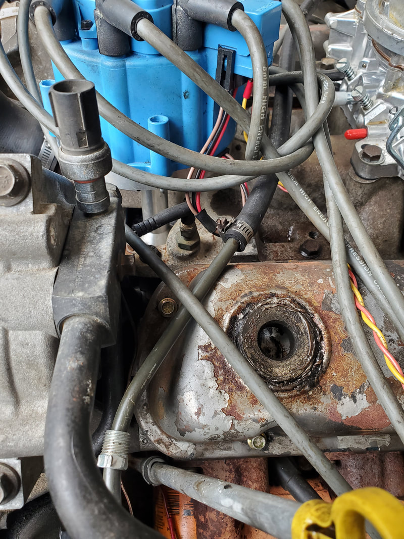
When we last left off, we had the multi-gauge box installed in the truck, zip tied to the steering column, with the wire bundles routed through the firewall and into the engine bay. The power wires were hooked up to a switched 12v power line and the gauge box tested to verify that the system would come on with the key. From there the next order of business would be hooking up the new sending units for the temperature and oil pressure. The temp sensor would be easy to reach as it's located under the distributor. The oil pressure sensor would be a little more problematic as its tucked away at a spot above the oil filter and behind the dipstick tube. But for starters, we hit the temp sensor first.  The old temp sensor, removed from its spot just under the distributor.  The new temp sensor, secured in place of the old unit. In order to reach the oil pressure sensor, I had to remove the oil filter, and the retaining strap holding the oil dipstick in place. I was able to move the dipstick out of the way enough to get a 27mm socket on the oil sensor, and use an extension with the ratchet to remove the unit from the block. Since the old sensor was 1/4" NPT and the new sensor 1/8" NPT, I had to source a 1/4" - 1/8" adapter bushing to use to secure the new sensor to the block. Once that was done, I moved on to the wiring. The bundle came out of the hole in the firewall where the steering shaft comes through. 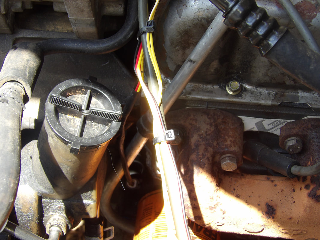 Oil sensor plugged in place, with dipstick tube secured and oil filter replaced. Note wire bundle secured and plugged to sensors. I routed the wire bundle up behind the brake booster and around the driver's side fender, around the stock wiring bundles, using zip ties every step of the way to secure the wiring. I came around the back of the fuse box and straight out to the right, towards the engine. I zip tied the wiring to the fuel tube as it is routed straight right towards the engine as well. From there the wiring pigtails are routed to their respective sensors. With that, I replaced the bracket for the oil dipstick and oil filter. Everything was ready to rock and roll. 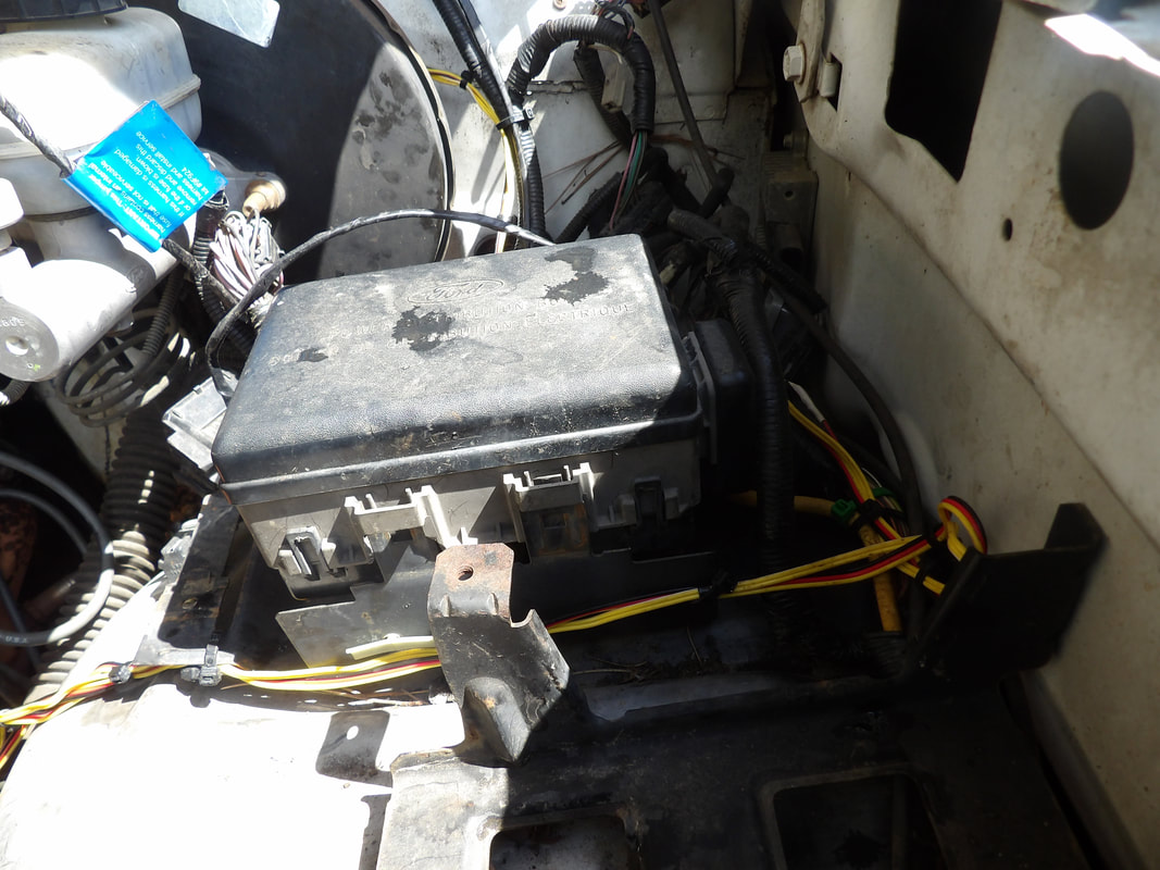 Wire bundle routed around same path as stock wiring harness, around fuse box and right towards the engine, zip tied every step of the way. 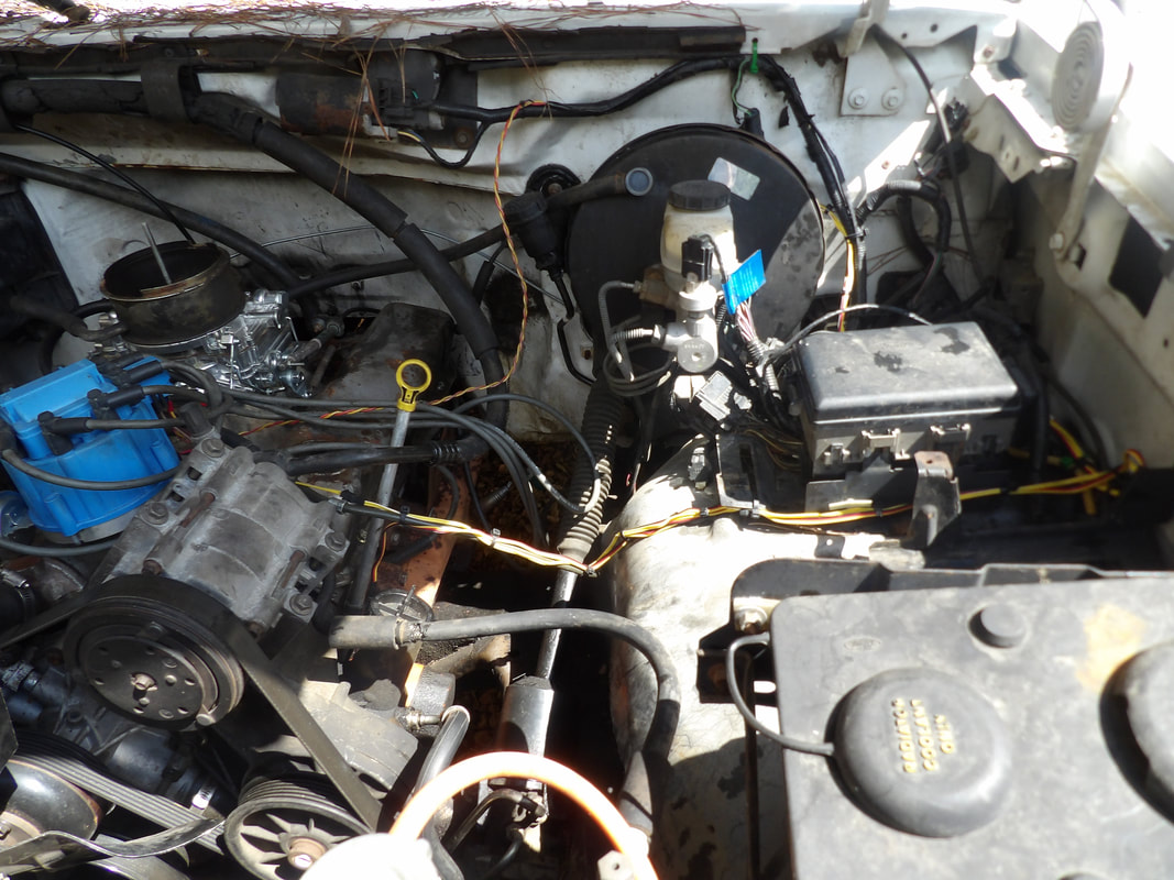 Wiring bundle secured to fuel tube as it makes its final approach to engine. After throwing some extra juice into the battery, I cranked up the engine and let it start warming up. The gauge started reading the water temp, in Celcius, as this unit is from overseas. As time progressed, the temperature warmed up on the gauge. The oil pressure, read in Mpa (whatever the fuck unit of measure that is), was showing 0.6, which according to the scale, is low as hell. Revving the engine up made the scale go up to 1.1 Mpa, enough to start registering on the gauge. Back to idle it went back down to 0.7. That pressure is low as hell, but not low enough to dry out the top end of the engine. 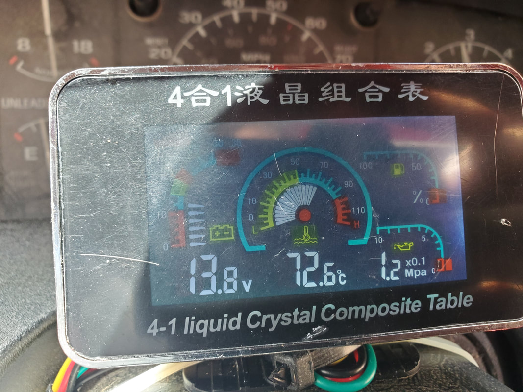 The multi-gauge operating as its supposed to with the voltage reading well, temperature reading and even oil pressure reading, even though its low. As the engine continued to run the temp got higher, getting to around 83 degrees celcius, which was about 3/4 the way up, but still reasonable. 100 degrees celcius would've been 212, which is about the normal operating temp for Chevy engines as I've noticed, so this thing was hovering around 180 give or take, which for all intents was pretty good, despite the lack of a fan shroud and the fan clutch slowing down the speed of the fan at idle. I'll probably still look at adding the fan shroud or even just converting to electric fans if the temp does go higher than this during future tests. As for the oil pressure, the pressure is low at idle, but I will need to do more tests to see what the normal operation of the engine is when its being driven as well as at idle. I might have to add thicker oil, oil treatment, more or less just play around with the system to see what kinds of readings I can get. This is an old engine after all and having low oil pressure is not out of the ordinary when its idling. As long as the engine doesn't start rattling like a diesel after warm up due to no oil getting to the top end, we can consider things good. All in all, the multi-gauge works as designed, voltage was reading good, letting me know that the alternator was also putting out too. I also discovered through some other research that the unit has a self teaching feature to allow it to learn the resistance of most fuel sending units so it can calibrate itself to that unit and properly read the fuel levels of that vehicle. I'll have to play around with that and see if I can get our multi-gauge to read the fuel level on the truck as well. It'll be cool to be able to remove all monitoring from the stock gauges and put them on this little multi-gauge in order to get more accurate readings. With the way this system works, I'll have to check into more units or other similar units that we can use later on for other applications in other vehicles to solve our no gauge/bad gauge issues, especially when replacement stock gauges are expensive. There's also still the matter of whether the stock wiring and the printed circuit boards on the backs of the gauge clusters are viable. In the end it will be way cheaper going this aftermarket route than to try and restore the stock hardware.
Since the last time we ran the FMT, no further work has been done on the truck. Reason being, the gauges weren't working accurately enough to tell me what the engine vitals were. I didn't want to run the engine any further until I knew what the oil pressure and temperature were, to prevent any possible damage from running too hot or too dry. After doing some searching for aftermarket gauges I decided to give this multi gauge unit a try. This device is a small flat screen display that shows readings for four different things. It has a voltmeter, oil and temperature, and a fuel gauge, for use with aftermarket fuel sending units. This device appears to be able to be mounted on a dash or similar horizontal surface, with the wires routed to their respective points in the engine bay and elsewhere. This unit was fairly cheap, and being small, would be a suitable replacement for the bad stock gauges.
Aftermarket multi-gauge, note the bundle of wires running from the unit. Also note the Chinese writing on the surface of the display, showing its origins.
The wires coming from the unit are rather long, allowing for plenty of wiggle room in routing the wires to the location of the sensors. This unit also comes with the temp and oil sensors, which would be screwed in place of the stock sensors on the engine. The wire for the fuel gauge would be routed back to the fuel sender if used and the power lines connected to a power point under the dash.
The first order of business was to find a suitable spot to mount the gauge. I didn't want to mount it on the dash where it would require me to secure the unit with screws, poking holes through the dash. As this is pretty much a temporary fix, I don't want to do anything that would permanently disfigure anything on the truck's interior. My solution was to zip tie the unit to the top of the steering column, using two ties to hold the base to the top, and a third tie around the neck of the base and the main mounting ties. The wires were tucked aside the steering column, under the dash where they'll be hidden, then routed under the dash where they can be further routed out through the firewall. I also zip tied the wire bundle for most of the way, just leaving the power lines free since they'll be hooked up at a point under the dash. The fuel lines won't be used so they stayed bundled with the lines for the oil and temp sensors. 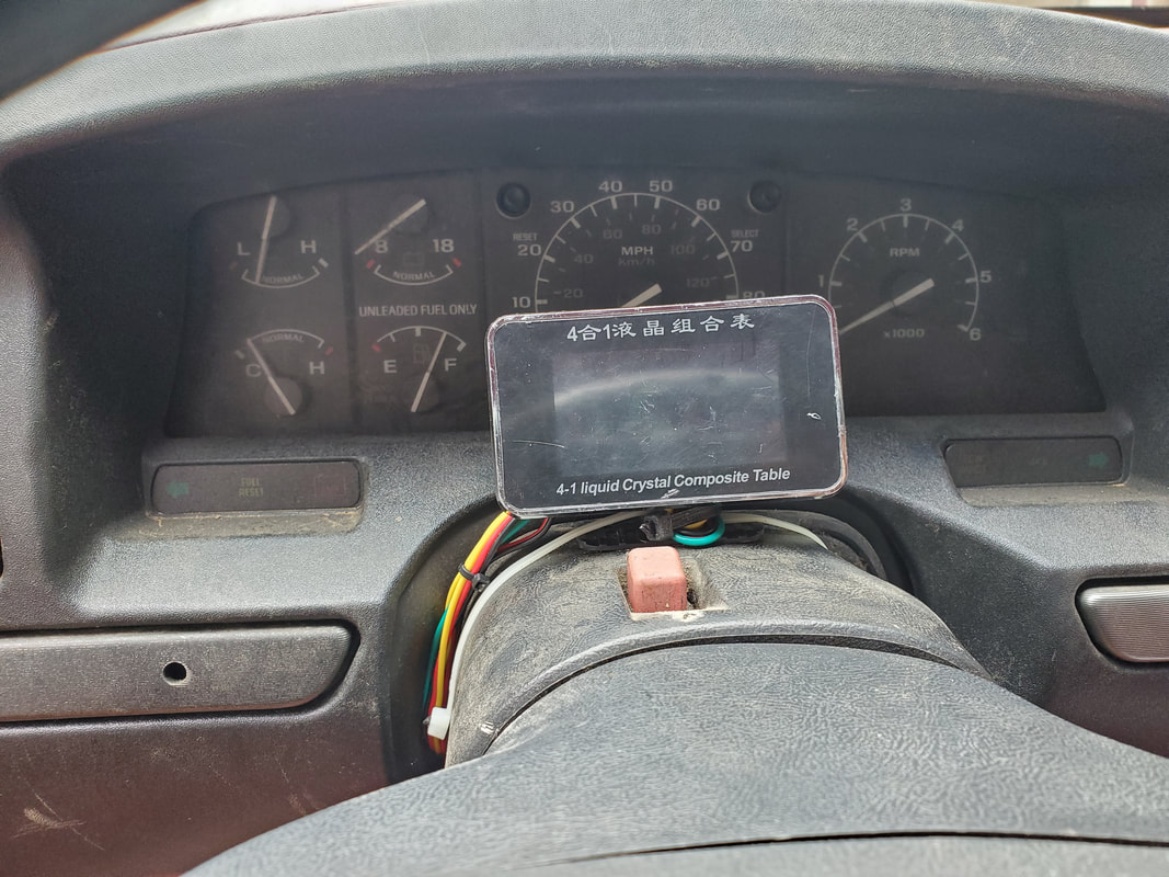
Multi-gauge mounted to steering column with zip ties. Note how wires are tucked behind the dash panel body around the steering column.
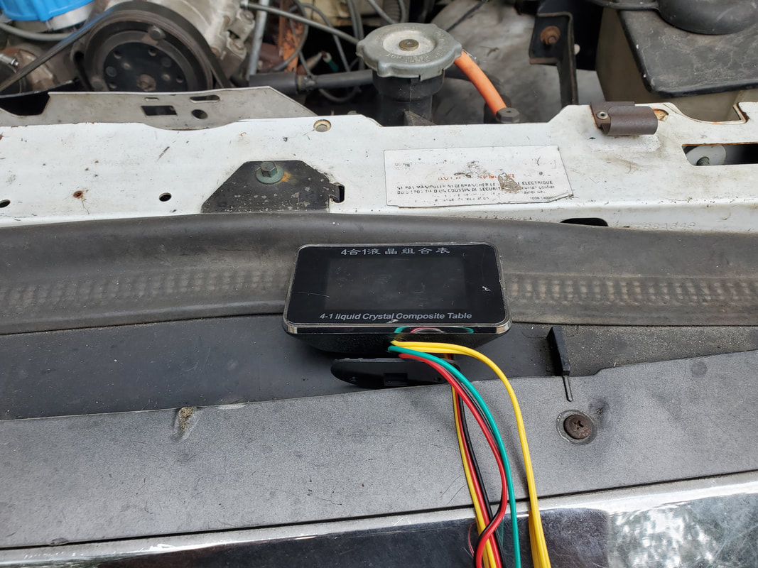
I routed the main wire bundle out through a hole in the firewall past the steering shaft since this point was wide open enough to facilitate this move without damaging the wires. I can add something to cover this hole at a later date when work is done on this truck that would involve running wires. I zip tied the wire bundle to keep things nice and neat and keep the wires tucked out of the way so my big feet won't end up snagging these wires and damaging them. The next thing I did was meter out and find a suitable switched 12v power wire in the existing wiring with which I can tap into. Using a clamping splice, I connected to a hot wire while securing the ground to an existing ground point that had its wire pulled out a long time ago. With that I had power to our multi-gauge unit. 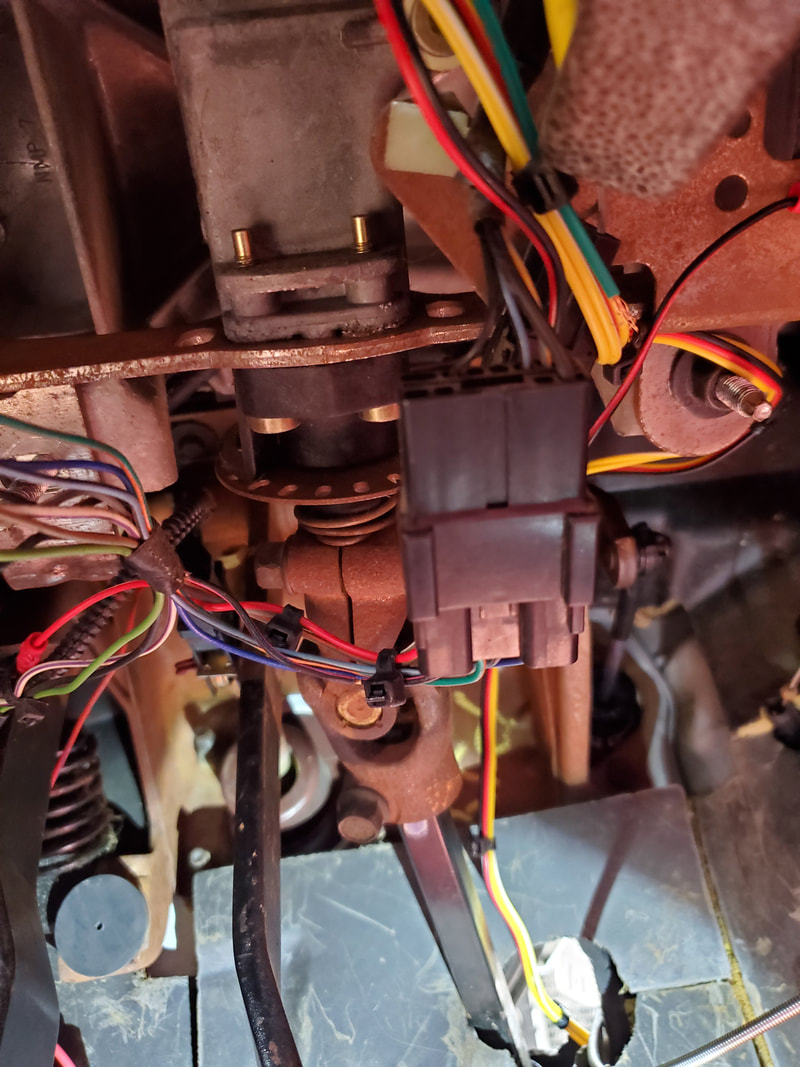
Wire bundle zip tied to keep it out of the way after it was routed out through a hole in the firewall to the engine bay.
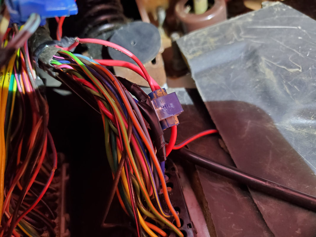
Clamping splice connector used to connect power wire from gauge to existing switched 12v power wire.
In the engine bay I unplugged the sensors in preparation for their installation on the engine. I will have to route the wires in a way as to keep them out of the way of the exhaust and keep things nice and neat so they won't be in the way of any other components I may need to remove during routine maintenance. I have plenty of wire to work with so I don't think this will be a problem. The temperature sensor is relatively easy to reach, being right under the distributor. The oil sensor is kind of tucked away, just above the oil filter, which might require removal. I might try to see if its possible to put a large socket on the sensor and remove it with an extension and ratchet before I investigate any further component removal to allow me to get a wrench on the item to remove it. Installing the new sensor for our gauge would require the same treatment, whatever that may be. 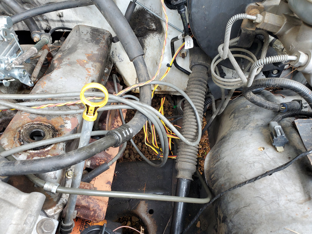
Bundle of wires where they sit after being routed through the hole in the firewall into the engine bay. They will have to be further routed from this point.
Temperature sensor right under distributor, making it somewhat easy to reach.
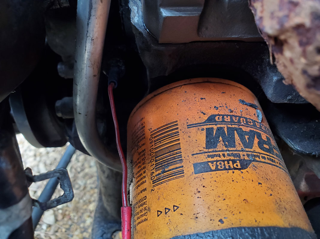
Oil sensor, tucked away above oil filter with just a single wire running into the shadows to mark its location.
I ran out of time today to finish the job but will pick up where I left off, getting the sensors installed and the wiring routed. From there I will have to run the engine in order to test if the sensors are working as intended. Hopefully all will work well so I can pick back up on the testing of this truck and be able to get closer to putting this thing on the road with a way to monitor the system. My final plan will be to get an A-pillar gauge panel and set of gauges to install within, so I can have things neater and somewhat "stock" looking compared to having gauge bodies sticking out from different points like the typical aftermarket gauge sets end up looking. We want to try and keep the "tacky" level down somewhat here.
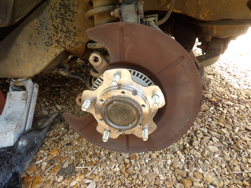
After riding around for a little time wondering why the steering on the Tracker would have me bump steering on occasion, I decided to jack the vehicle up to see what was up. I quickly discovered that the left wheel bearing had play, enough so to warrant me laying up the vehicle after the last drive to and from the job. I don't want to take a chance continuing driving and have this thing break while rolling down the highway. In the process I did order a set of wheel bearings so while that's en route I decided to take the bad wheel bearing off, especially since I never removed one on this vehicle. This would be a first time experience and I'd rather have an idea of what is involved so I could get the job done more sooner than later.
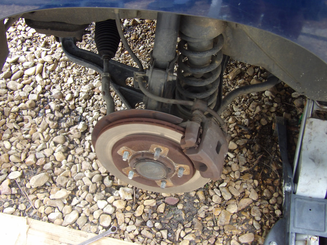
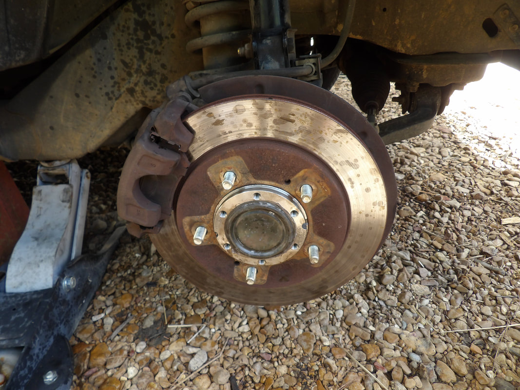
Our spindle/hub assembly after removing the wheel.
After pulling the tire off the hub, first thing I had to was remove the brake hardware. This involved pulling the brake caliper off, then the pads, clips and the caliper bracket, which would then free up the rotor as well. A few bolts had these components removed pretty fast. 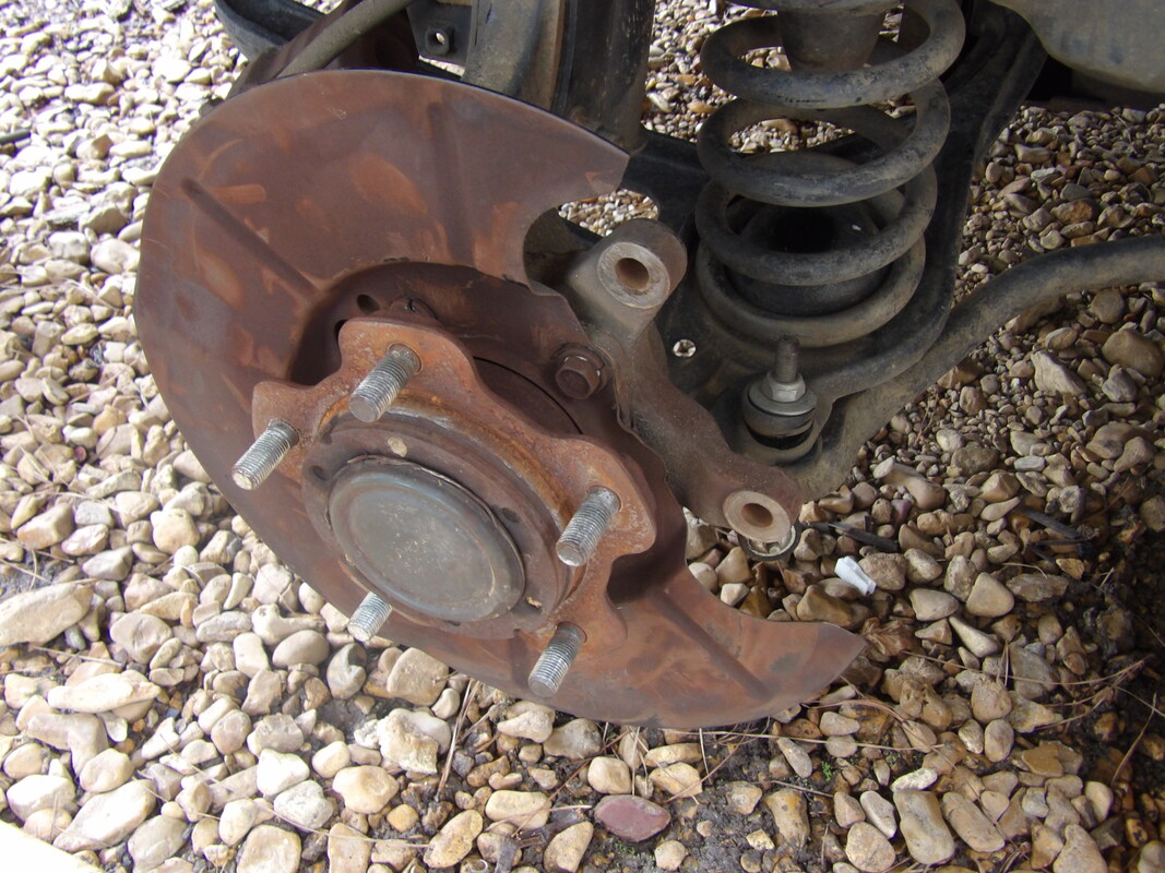
Spindle/hub assembly after removing the brake hardware in order to expose the hub assembly.
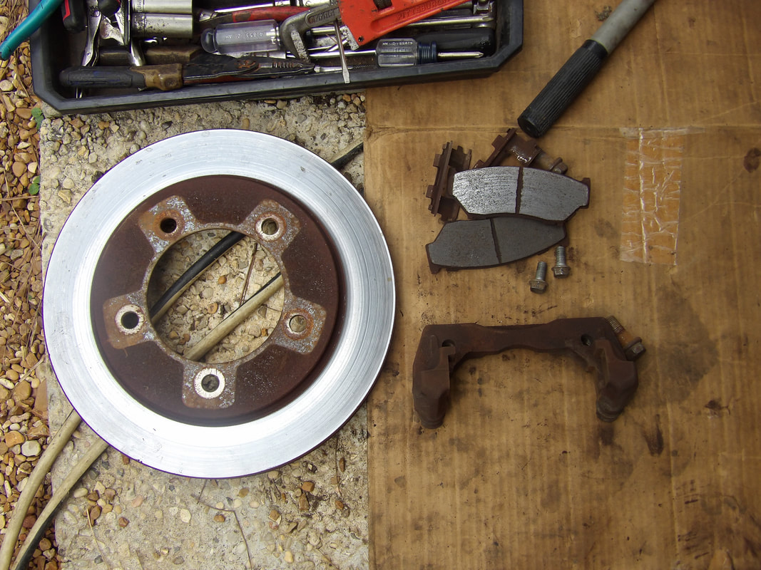
Brake hardware removed from spindle.
Now the wheel bearing isn't like a wheel bearing in the Scion where it needs to be pressed in. This is a bearing/hub assembly. From what I observed, it is held onto the spindle by four bolts. I wasn't exactly sure how this hub assembly comes loose further at the time, so I removed the four bolts to get the unit off. With the unit on the ground, I also found that the brake shield was still on the assembly. How the hell does this come off? 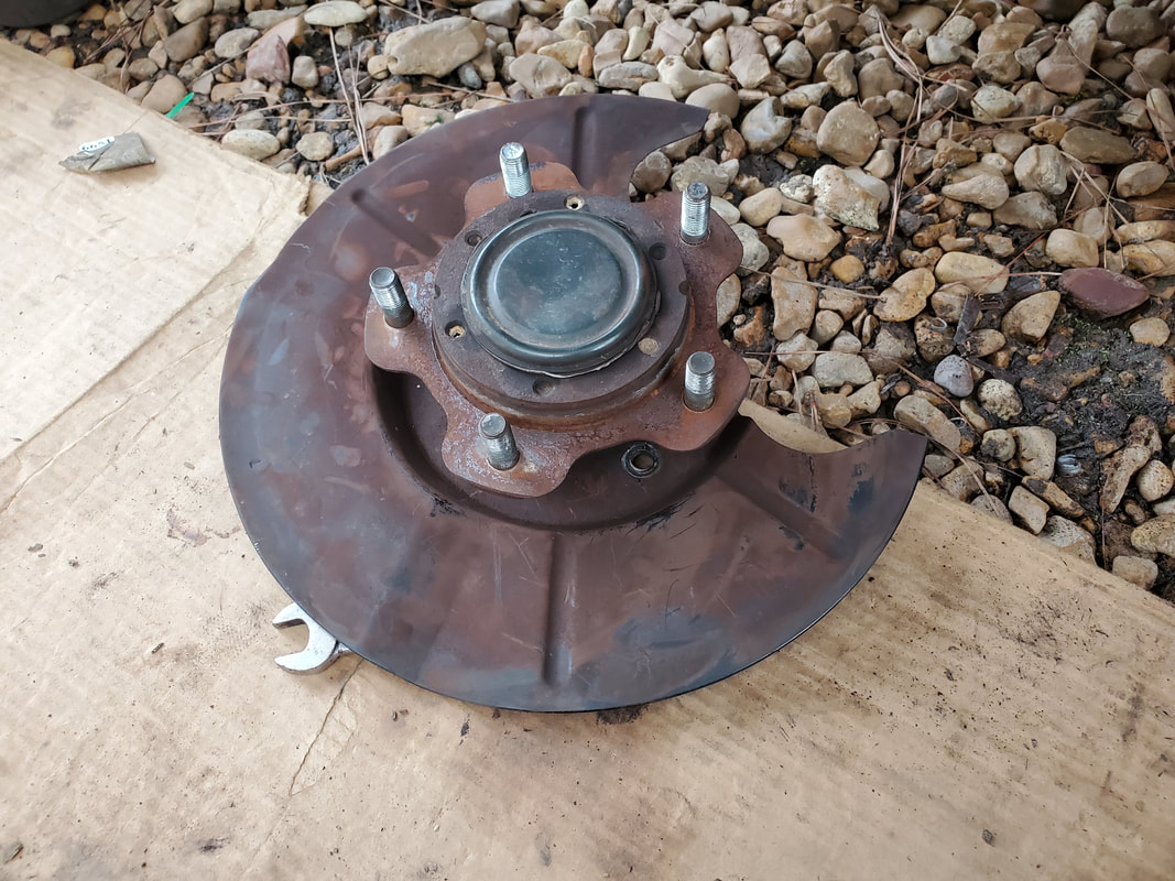
Front of the hub assembly with the brake shield still on. Note the center cap on the hub.
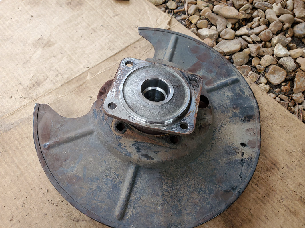
Hub assembly with axle body and brake shield in place. This is the back surface of the axle that bolts to the spindle.
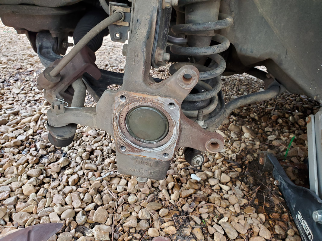
Base of spindle after removing the hub assembly.
Looking at the hub assembly, on the actual hub there appeared to be a center cap, similar to old school cars where a center cap covered the axle and the set of wheel bearings. With a screwdriver and hammer, the center cap was removed, exposing the wheel bearing and what appeared to be a retaining ring that was held by four screws and a groove on the axle to the center hub of the wheel bearings. Next move: remove the four screws. 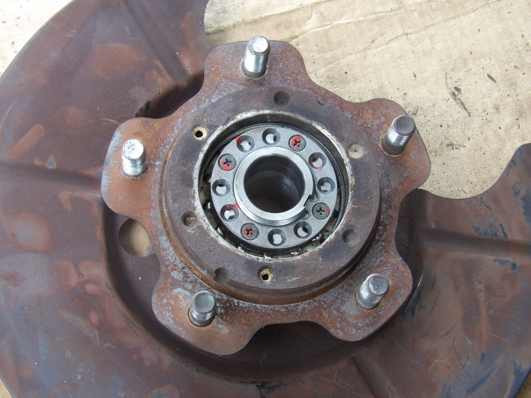
Bearing with retaining ring held in place with four Phillips screws to the center hub, which is screwed onto the axle to hold the hub assembly in place.
The first two screws immediately stripped out, the other two came out easily. I ended up having to drill out the stripped screws in order to free up the ring. Once the screws were out and the center ring was removed, a screw down ring was screwed off the axle, allowing the hub assembly came apart quickly. Of course this freed up the brake shield. Now, looking at the pieces, I found that the axle piece that was held by the four bolts really didn't need to come off. I could've left that part on, and just popped off the center cap and that retaining ring, allowing me to remove the actual hub assembly that will need replacing. 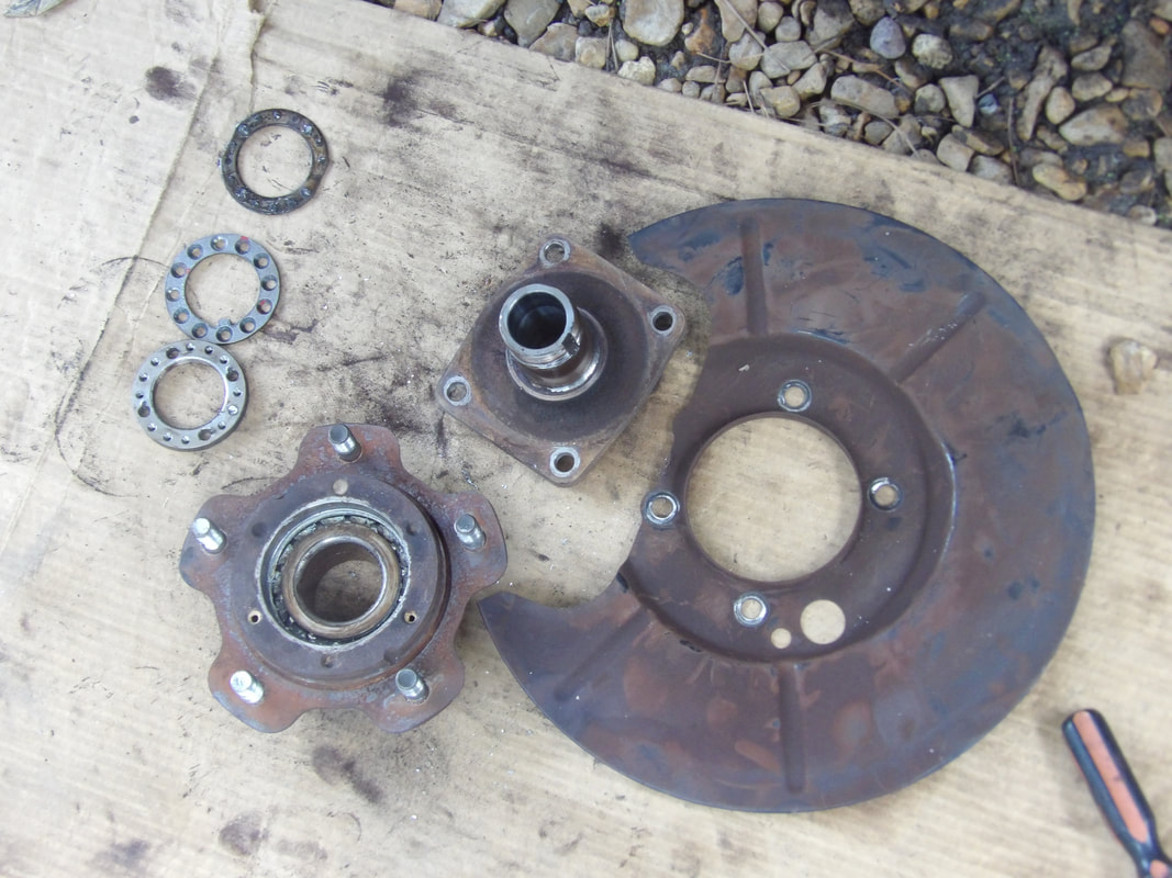
Bearing/hub assembly separated from axle and brake shield with retaining rings/washers.
With this knowledge of how the wheel hub assembly goes together, or comes apart, I can now replace the unit when the new parts do come in, and get the other side replaced as well, even though it isn't bad. I'd rather replace both sides as one unit versus doing one, then waiting for the other to go bad. If I do anything, I'll possibly order a second set of front wheel bearings and put them up for future use. But for right now, I learned how the front wheel bearing assemblies on the Tracker.
Sometimes around here, there is no set thing for us to work on, but several things. Most of the time the things are pretty small, just some little thing that needs to get done but only takes a second to do. It doesn't take away from the importance of the task being something small, so the stuff still gets done. Of course some of these small tasks are the beginning of a greater project or series of tasks, such as the case with the main driveway. I've been looking at trying to get the main gate up and working and to make things easy, I would like to be able to narrow the opening to 16 ft, down from the 20ft it currently is. Now I could build a fence that spans this opening but it would be more expensive than to just work with a 16 ft opening, for a couple reasons. One, a 16 ft fence would be cheaper than a 20ft fence (which really has to be more than the gap if its going to be a sliding gate), and for all intents on the low end I could just use a couple 8 ft gates, if I just want to get the gate closed in. This narrowing of the opening poses a problem though. To be able to swing out into the driveway, the driveway would have to be wider across the opening and out past the gate on either side. Otherwise, when I pull a vehicle out, or in, I would have to swing out into the grass opposite the fence line. Problem here is the idea that there's depressions that are rather deep and have swallowed tires to the point that I would have to use a truck to pull the stuck vehicle out. To remedy this and prepare the surrounding area for the modified gate, I'll have to fill in this depressed area and level it off with the driveway, which will incorporate bags of concrete for the larger holes, poured concrete to fill gaps and gravel to top off and level off things. 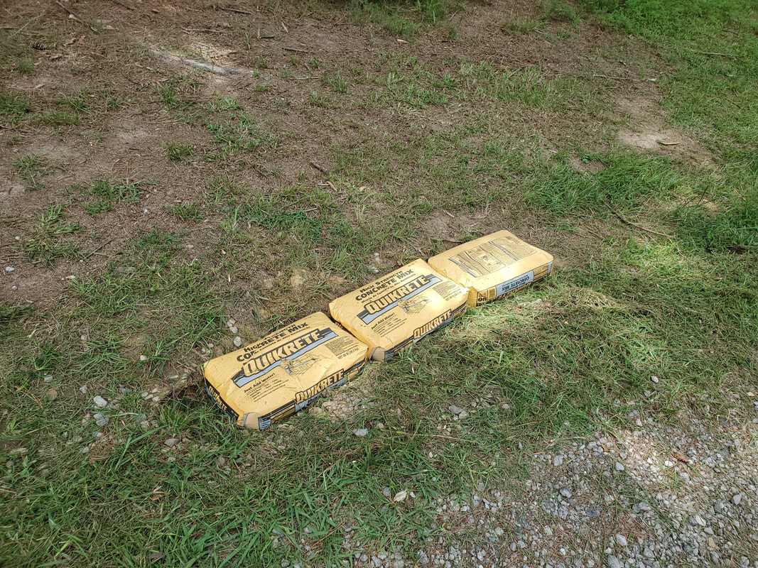 The beginning of filling in the grounds around the driveway, three bags of concrete to fill the deepest point of the depression next to the driveway. Moisture from rain and the ground will soak into the concrete and harden the bags where they'll be like giant bricks filling the depression better than a lot of loose gravel would. Another thing that I was working on that needed a little something else was the winch on the car trailer. After mounting the winch on the welded mountings I did, I still had to attach a hook to the cable. I'm also waiting for the remote control cable assembly so I can test the unit out. Along with the concrete, I picked up a 5600 lb rated hook, one of the open hooks, not the narrow hooks that are typically on tow chains. With the hook taken care of, once the cable assembly comes, I can complete the winch (of course I still need to install a battery). From there I can attempt a test of the unit in real time.  Heavy duty hook attached to the end of the cable on the winch, making the winch ready, just needing the remote control cable and a battery. Of course, there's always other little tasks that are pretty routine that need addressing around here, like harvesting of veggies from the garden, occasional pulling of small weeds in the raised beds (not sure how this shit ends up in these beds), routine cleanup of different crap around the grounds, and some occasional car maintenance. The Tracker is in need of front wheel bearing replacement and rather than continue to ride until the thing breaks and the wheel falls off, I'll be mothballing the car for a minute while I wait for the replacement parts. In the meantime, I did have to replace a couple tires on the S10, since the front tires were a little worn. One was more worn than the other however, so I replaced that one, and replaced the tire on the spare rim I had as well. Since the Tracker won't be used for a spell, I had to take care of this little bit of business so I can use the S10 without any risk of incident, as it would be just like it that I lose one of these shitty tires when I don't have a spare. More on the Tracker soon.... After fixing the garbage hose that I hooked up for the Minivan Coop, soon as I turned the thing on and filled the bucket reservoir, the damned hose ruptured right at the end junction, soon as the float valve shut down and pressure built up in the hose. I removed the garbage hose and after getting a replacement 50 ft hose for the reel at the driveway, I used the heavy-duty hose that was on the reel as the donor for the Minivan Coop. It had a repair end on the thing so after removing that end I was able to connect the hose to the 4 way junction and run it through the trench (which I had to dig up again). From there I zip tied the hose to the post and cut the hose down at the regulator. I added the end back in place and had the water system connected and fully online, with no leaks. 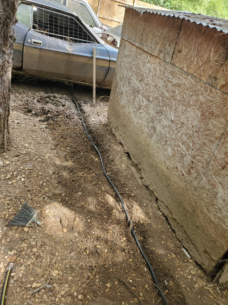 Heavy duty hose laid down to replace the first hose that failed multiple times. 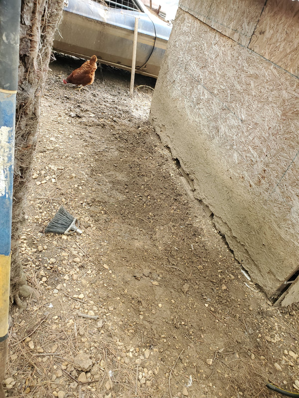 Trench filled back in, again, after replacing the hose. 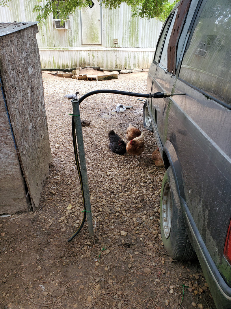 Heavy duty hose tied to post with connector hooking it up to the regulator. With the water system back online, I moved on to filling the bulk feeder in the coop with feed. Surprisingly, it turned out a 50 lb sack of feed filled the feeder up to around 3/4 full. I could've put another quarter bag of feed in the unit to top it off. This is promising as the system would be plenty able to sustain the birds for a good long period of time. If I use the other smaller bulk feeders, we should be able to keep the population fed for a good couple weeks. 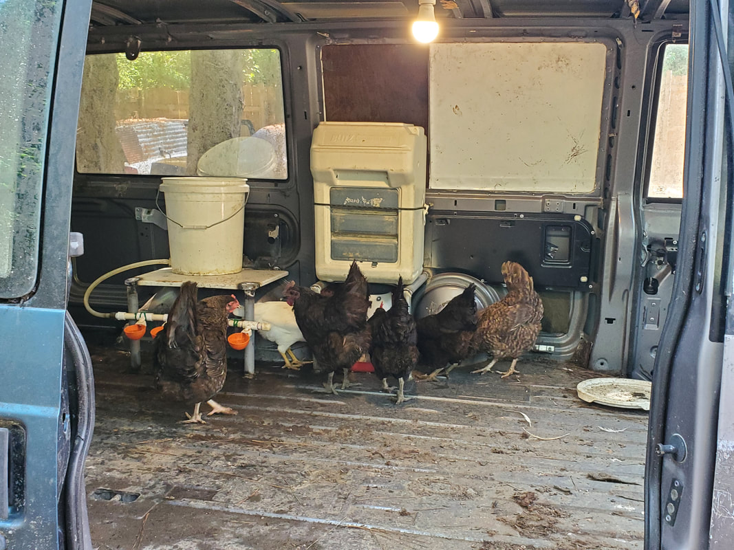 Birds congregating around the bulk feeder, helping themselves. I also had to do one more little modification to the coop prior to adding hay. At the front doors, the step area is lower than the rest of the floor. I added a couple pieces of sheet metal over these points to cover them up so hay, chicken shit and other garbage don't end up collecting at these points where they would be unable to be cleaned due to the doors being welded shut. The sheet metal was cut and bent to allow me to secure the pieces with self-tapping screws to the floor and the door bodies quickly. With those door sill/step areas covered up and the floor more or less leveled off, I was able to add some hay to the coop to give it some bedding for the birds to do what birds do in coops. 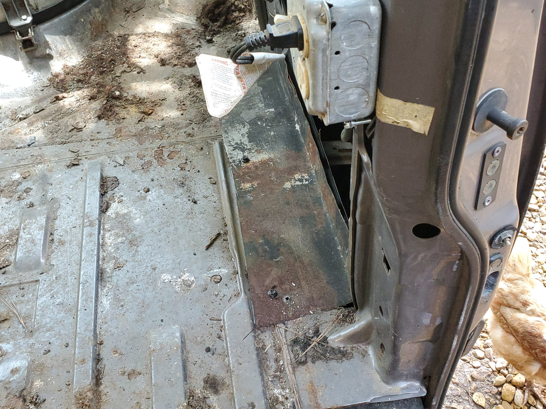 Sheet metal patch added over door sill/step at front door to cover this garbage collection point. 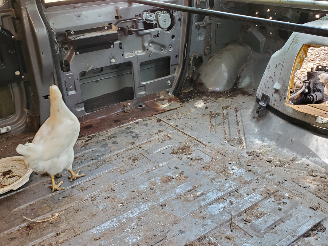 Other sheet metal plate at other door, secured the same way as the previously shown unit. 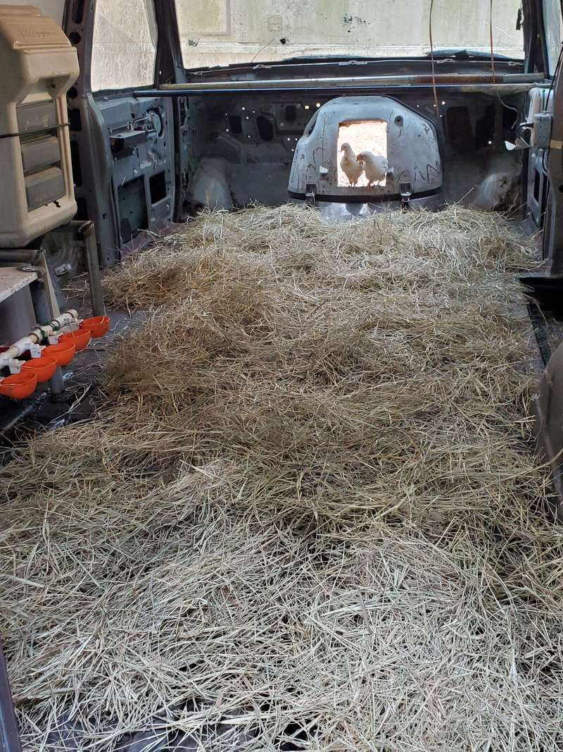 Hay spread about the Minivan Chicken Coop to complete the whole setup so the birds can enjoy the facilities as intended. With the coop done, I was able to start laying gravel, now back in the chicken yard. Even though I was at the side park going into the backyard, I moved back to the chicken yard. I had to cover the trench for the power cable for starters, but instead of the hose trench, which I ended up having to dig up again anyway, I laid gravel down over the back area of the chicken yard, behind the Mustang Chicken Coupe and S10 Ranger Coop. This area became a collection point for water and was rather sloppy. I'll be laying gravel all over this area to raise the level up and hopefully cover up the slop so this area will be more pleasant to navigate through in the future. 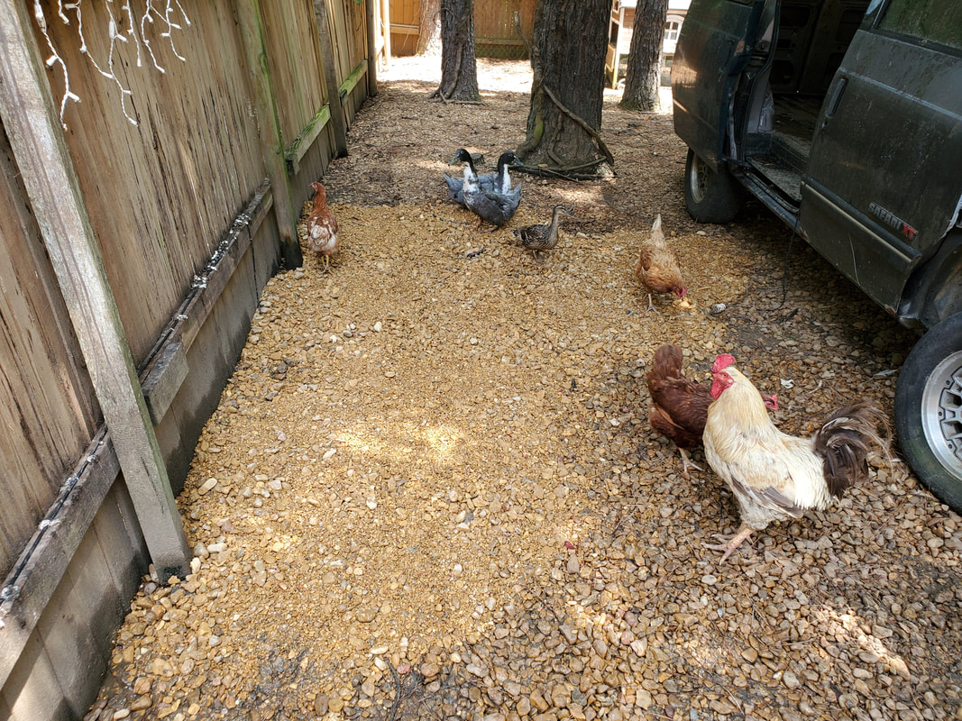 Gravel laid over area where power cord trench was dug and filled back in. The surrounding area also took gravel to help cover the sloppy area better. 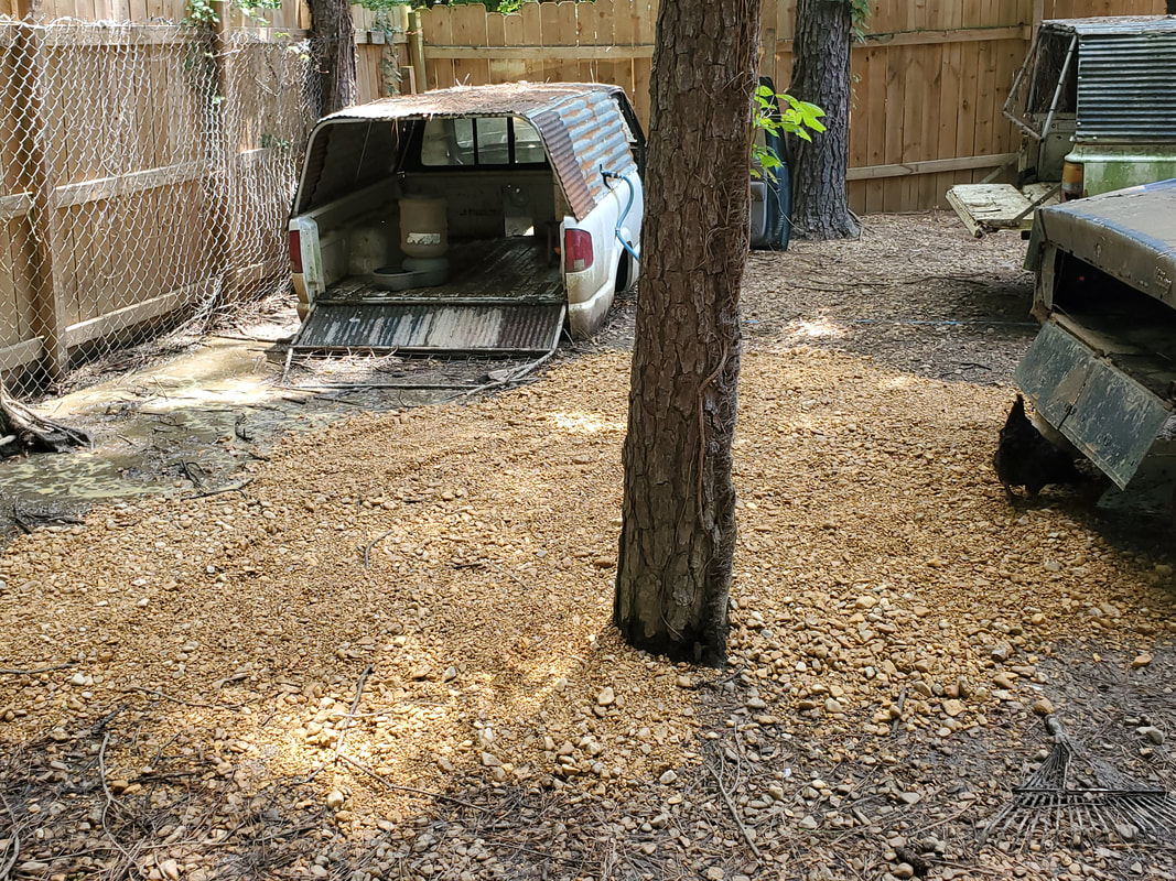 The back area of the chicken yard getting covered with gravel to cover up the super sloppy area that remained wet for so long. The more gravel gets laid the better this area will become where it will be more pleasant to walk over. With the next load of gravel, I'll be able to cover the trench area where the hose was laid, as well as the surrounding area. Even the areas around the Mustang Chicken Coupe can use more gravel to raise the level up and cover up the muddy sloppy areas as these areas remained wet all the time, making for a messy area. Trying to keep the watering apparatus perfectly sealed is problematic and the myriad leaks have it where the area stays wet and as the birds do their thing over the area, the ground gets worse. With the newly laid gravel, even with the leaks, the area won't be so bad as far as slop and mud is concerned.
After setting up the winch on the car trailer, as well as resurrecting the winch with a new solenoid to make it operate in both directions, there was one more order of business left. I still had to install the battery box so I can get the needed power to the winch. Since this is a heavy load device, I can't get power from the trailer light harness (Even if I had one on the trailer). This would be a rather simple job though, just requiring some scrap metal and a little drilling and welding. The first thing was to install some angle iron to provide the support for the box, and obviously the 40+lb battery that it would contain.

Scrap angle iron welded in place on A-frame of trailer for supporting battery box.
I pulled the last piece of angle iron I had in my scrap pile, which was actually two sections welded together lengthwise. After cutting the weld and separating the two pieces, I ground spots on the trailer frame so I could weld the angle iron in place. I cut the excess from the outside of the A-frame and ground the sharp edges down. From there, I moved on to the battery box. To address this, since the box is plastic, I didn't want to just drill holes in the bottom of the box and bolt it to the angle iron as the box could break at these points and allow the box to pull free with the battery inside. To remedy this, I cut a piece of stiff plate/sheet metal and used it as a base on the bottom of the battery box. 
Plate metal cut to fit in bottom of battery box to help secure box to angle iron.
From here I drilled four holes through the plate metal and through the angle iron. I applied 3/8" bolts with lock nuts and washers to both sides, so the washers are applying force against only metal, sandwiching the plastic bottom of the battery box between the metal. This way, even if the battery does have any movement, it won't pull free from the base. 
Battery box with plate in place and bolted down holding the box to the angle iron.
On the battery box, the unit contains a divider piece that allows for different size batteries to be used, which is good, as I won't be using a larger 29 series battery in this thing anyway. I'll more than likely be using a borrowed car battery to power the winch when I do use the trailer. The box also came with a strap to help secure the battery, I still have to see how that piece is utilized but the main thing is the box is locked down. 
Battery box with divider in place. Note power cables being situated on the sides the way they'll be when hooked up to a battery.
I still had to route the power cables from the winch to the battery box. The lid is made so cables can be routed from the sides up and into the box where they can be connected to the battery and the box lid snapped back in place. With the cables situated as they would be when the battery is in the box and the lid snapped on, I used a couple zip ties to secure the two cables together in order to keep things neat so the cables aren't just flopping around loosely. 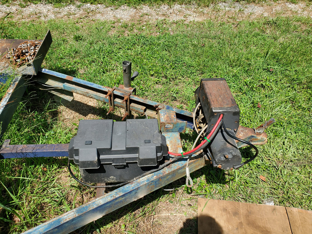
Battery box mounted on angle iron bar with power cables secured in place under normal use conditions.
The winch system is pretty much completed, minus a couple things. Of course, there's the battery, but I wouldn't leave a battery in the trailer anyway. When the time comes to use the trailer, I can slap a battery in place and ride out. The cable on the trailer still needs a hook, which is a low-level problem, just a trip to Lowe's and a few minutes bolting the hook in place. From there, I do want to install trailer lights and wiring so I don't have to use the magnetic lights every time, I can just hook the trailer up and plug the lights up to the truck and ride out. I also want to fabricate some kind of mounting setup or at least a latching setup to hold the ramps to the mounts on the middle of the trailer. This will just involve adding some metal in the right places. I also want to add a storage box to hold the remote control cable for the winch, along with the ratchet tie downs and a socket wrench for the tire lugs. Lastly, I'd want to add some kind of mount for a spare tire to hold one in place so I don't have to worry about grabbing a spare when I plan to drag the trailer down the road. I do have to replace the tires on the rims on the trailer anyway so the need for a spare is lessened. With all this done, the car trailer will be a self contained piece of equipment, ready for use at any time with little fuss.
As is always the case with these projects, there is always one thing that tends to give one problems. In our case, it was the water system. I had a problem trying to get the water system set up where I wouldn't get a bunch of leaks. I had leaks at almost every junction along the system from the 4 way at the Mustang Chicken Coupe all the way to the bucket reservoir. I had added a short length of new garden hose from the 4 way, going under the Mustang Chicken Coupe to the right side, just shy of the trench. From here I had to remove a section of the garbage hose near the end where there were several leaks, luckily I had a couple of press fit couplings left. 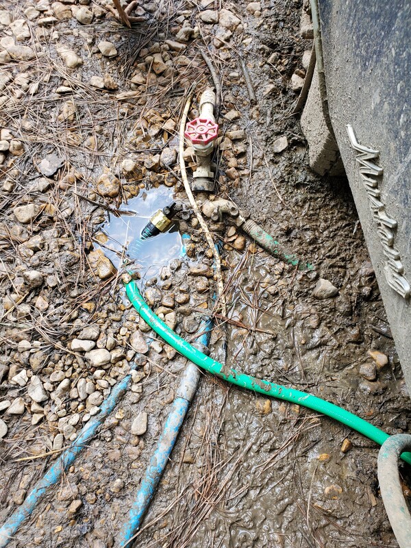 New short garden hose hooked up to 4 way fitting at Mustang Chicken Coupe. I cut a short length of the hose from the end where I had another press fit end. I left about a foot of hose on the end and cut the hose back part way into the trench, removing a good section of hose to ensure I cleared all the bad area of the garbage hose. I used a press fit coupling that allows two bare ends to be coupled together to put the hose back together, then connecting the end of the garbage hose to the end of the short garden hose. At the Minivan Coop, I took a fence post I had and sledgehammered it into the ground a couple feet from the side of the van's side, then used zip ties to secure the above ground section of hose to the post. I had to disassemble the end on the hose and add some electrical tape and a longer wood screw to the plastic clamp to ensure a good snug clamping action on the nipple end in order to seal that leak point as well. With those leaks addressed, I moved on to the bucket reservoir. 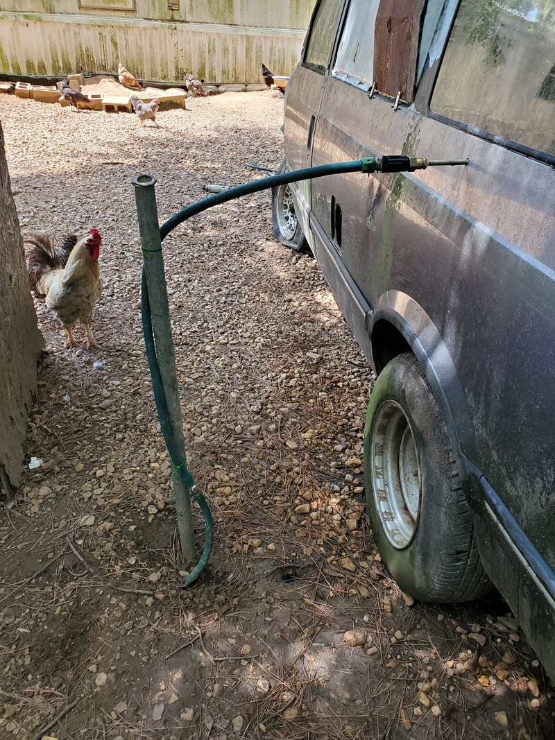 Fence post sunk in the ground and hose secured with zip ties to the post. As stated before, I had to replace the bucket due to hairline cracks in the sides. I took another fresh bucket and drilled fresh holes for the output nipple and the float valve. To help in sealing the output nipple, I used teflon tape on the nipple's threads and hot glue around the inside and outside of the fitting. This would ensure sealing all around when the bucket is full of water. I had to disassemble the float valve to remove some dirt that was clogging the thing, but once that was all put back together, I had a bucket reservoir that no longer leaked, and pumped water out from the float valve as intended. 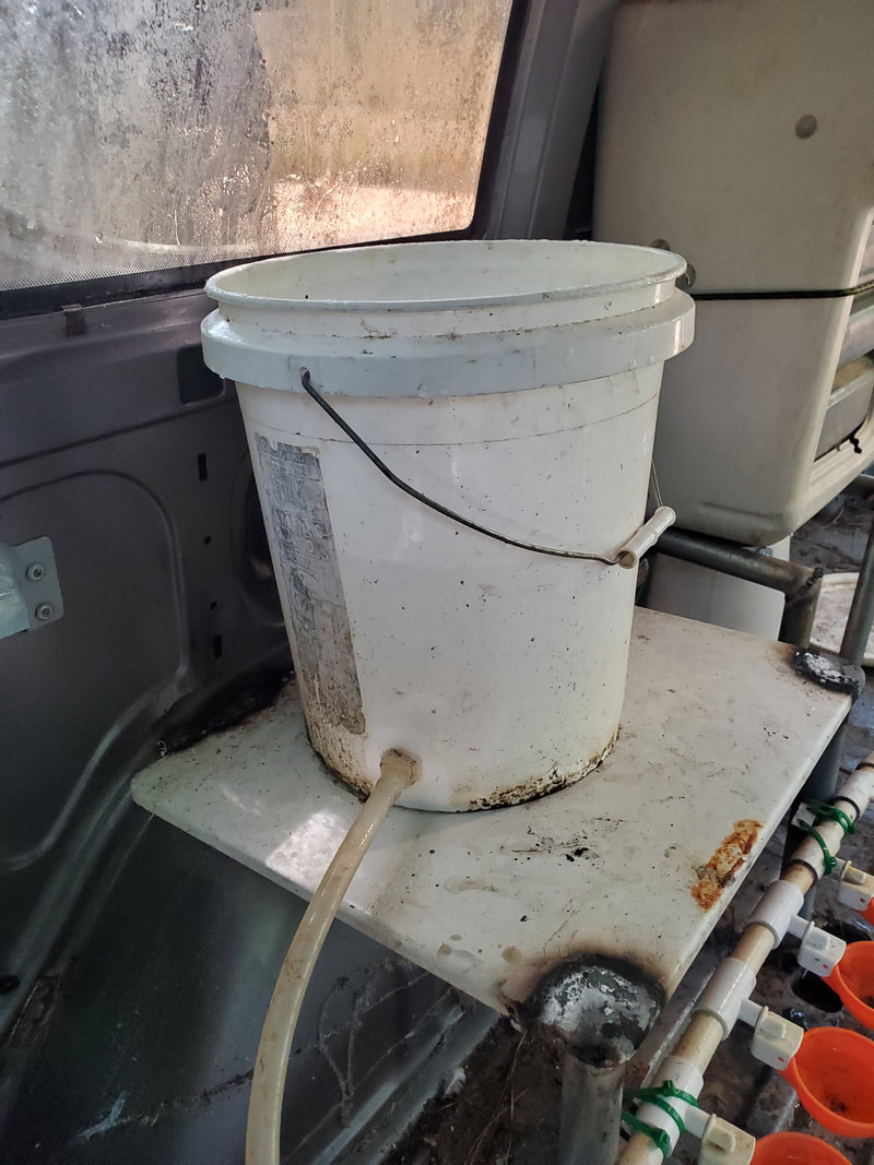 New bucket reservoir set up on the watering station. With that, the water system is ready to rock and roll. Short of a failure on the garbage hose's part, the whole Minivan Chicken Coop is completed and ready for action. Chickens have already been roosting on the posts at night and the chicken shit on the ramp and inside show that the birds have been moving about throughout the coop. We just have to get bulk feed to fill the feeder, so the birds can get used to going inside and feeding and drinking. Mulch/shavings will give the coop that typical homey feel for the birds where they'll be more likely to congregate inside and maybe lay some eggs, even before I figure out some nesting box arrangements. Of course when I do figure out a viable design, I'll be sure to post that here as well as on the YouTube channel. With the trenches dug for both the water and power, the next move was to get the materials to set things up. For the water line, my plan was to use a length of garden hose, hooked up to the 4th tap on the 4 way adapter by the Mustang Chicken Coupe, route it under the car, then bury the rest of the hose in the trench, all the way over to the Minivan, where the hose will come up from the ground and over to the regulator. As for the power, there's an extension cord end that the old Christmas lights are plugged to that I will tap into. I'll remove the plug and splice another length of cable into that cable end and route it over to the trench leading over to the plug at the Minivan. But right now, we start with the hose. I "borrowed" this old hose that was connected to a newer hose on our reel in the driveway, with the intent of using a length of it to make the water run. 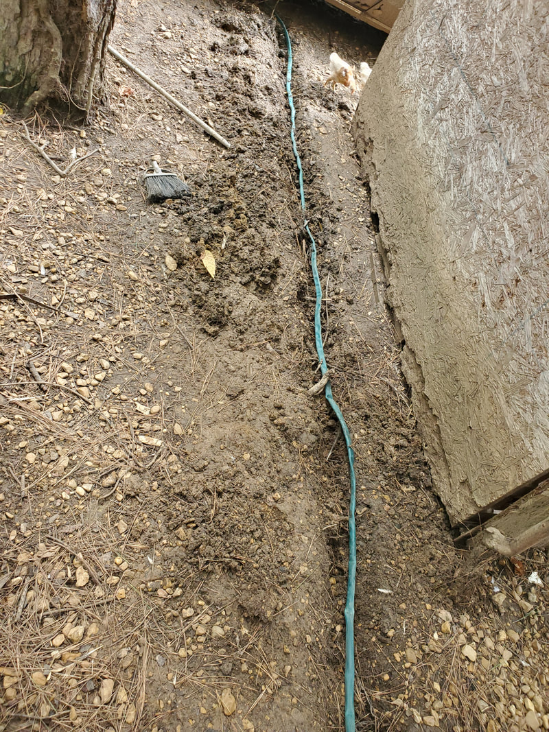 Old garden hose laid in the trench coming from the Mustang Chicken Coupe. With the hose hooked up I buried the length of hose in the trench, and turned the water on. First time there was a leak that popped up at the length of hose coming up from the ground and going to the regulator. I ended up having to cut that section free then taking another section of the old hose, which happened to have a coupling already in it from a previous splice, and hooking that up to the line and reconnecting it. That took care of that leak, but then another one was popping up right at the damn fitting on the 4 way. I ended up cutting the end off and taking an aftermarket press fit end and applying that to the hose. Once that leak was taken care of, then some more leaks surfaced at the length of hose under the Mustang. WTF!?!? So now, the next plan will be to insert a new length of hose at the 4 way and under the car and connect to the end of it. I'll end up wasting another press fit end, but if it gets this whole water line working then so be it. 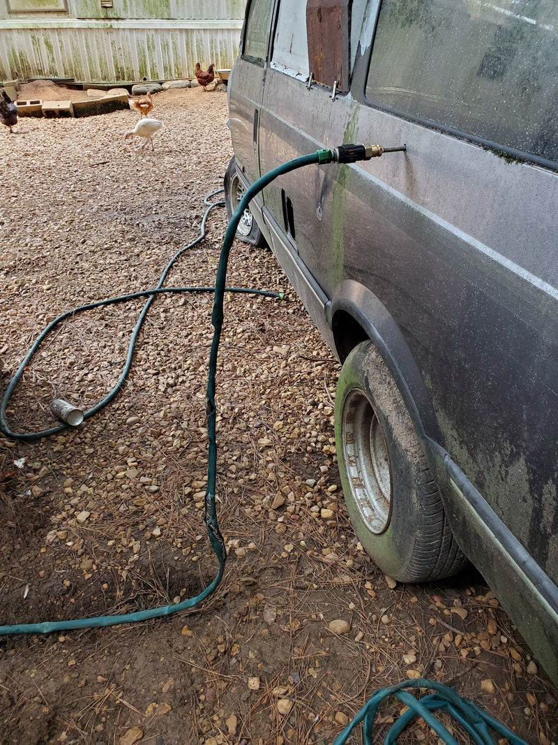 Hose coming up from the trench and connecting to the regulator going into the Minivan Coop. 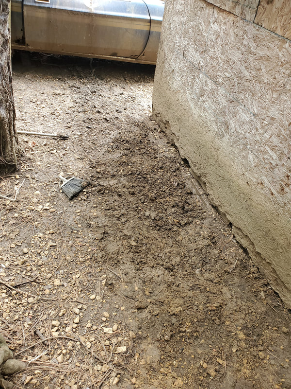 Trench for hose line filled back in and leveled off. With the water line more or less established, I still have to find a length of fence tube or pipe or whatever that I can tap into the ground to tie the above ground hose to at the regulator. In the meantime, I turned my attention to the power line. I removed the plug from the extension cord end and spliced in the new length of cable I dug out, covering the individual splices with heat shrink tubing, then covering the whole works with a larger piece of heat shrink tubing. I then used U-tacks to secure the cable along the lower 2x4 of the fence all the way over to the spot just above the trench. I laid the rest of the cable in the trench then installed the plug back on the end of the new cable, plugging up the Minivan's power plug to it. I filled in the trench and plugged the other end up, establishing power to the Minivan Chicken Coop. 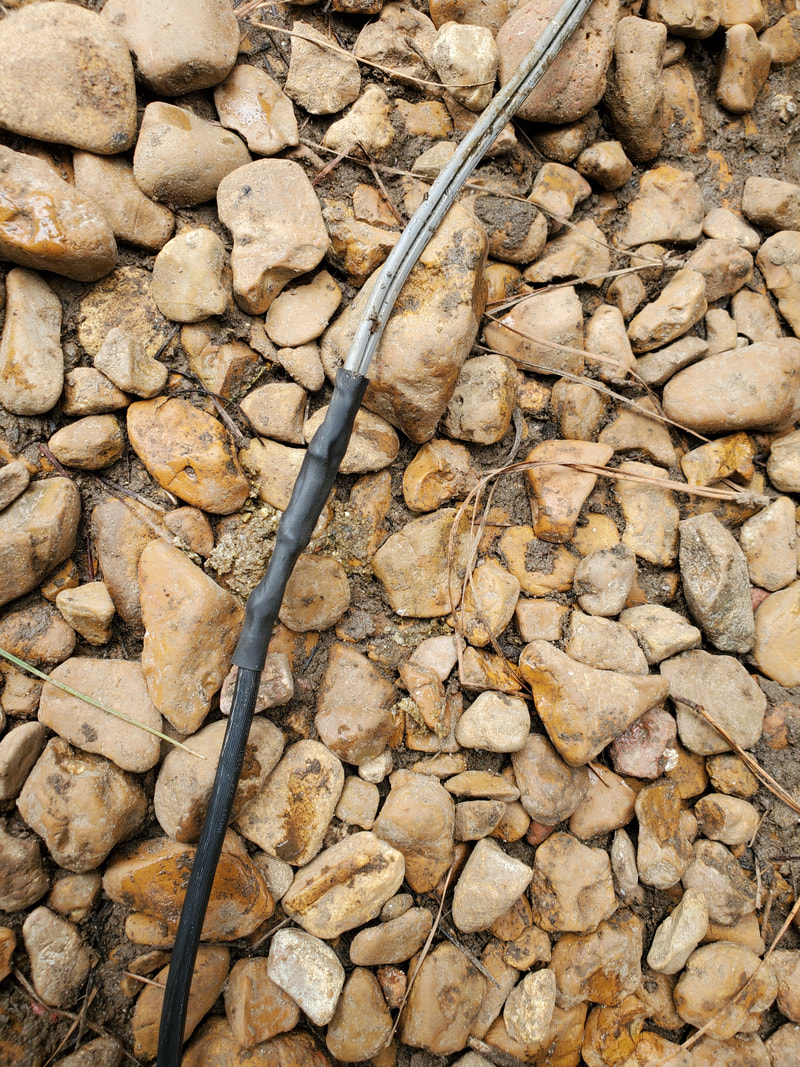 Heat shrink tubing covering splice of old extension cord and new length of cable. 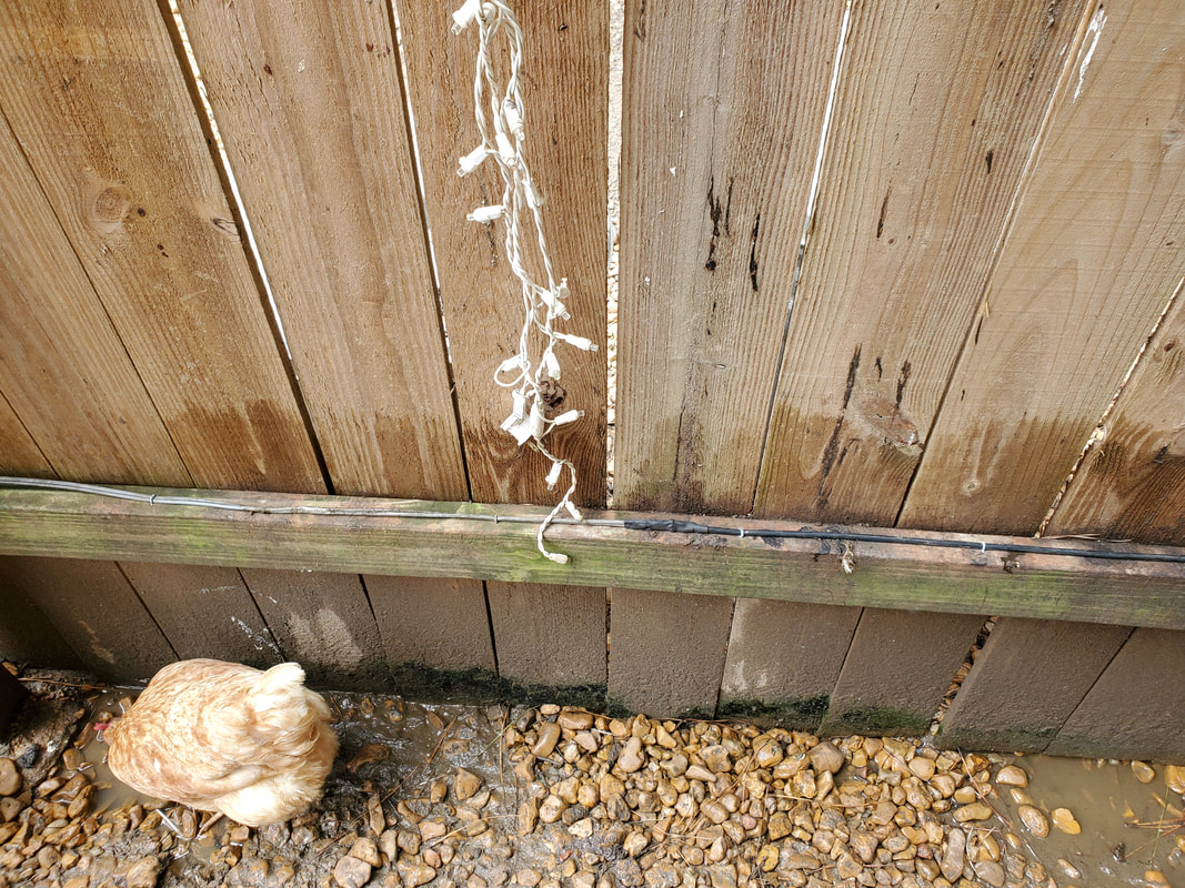 Cable tacked in place along the lower 2x4 of the fence, keeping things nice and neat. 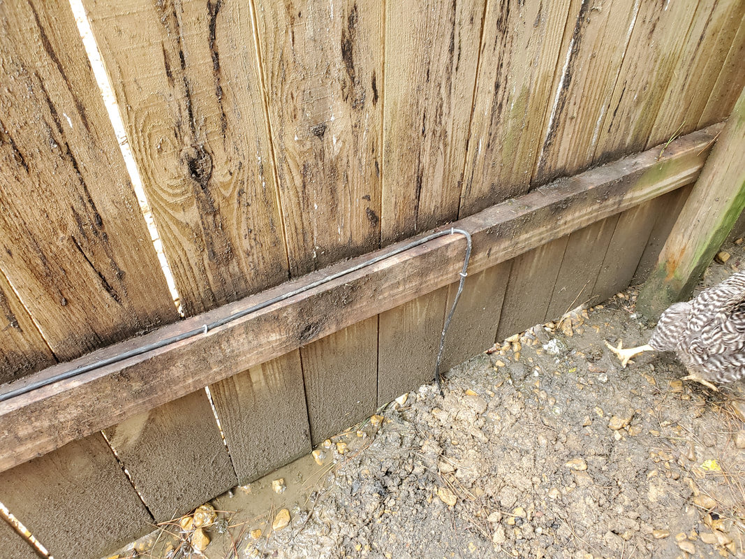 Cable tacked over to where trench is, then routed down to trench where rest of cable is buried. 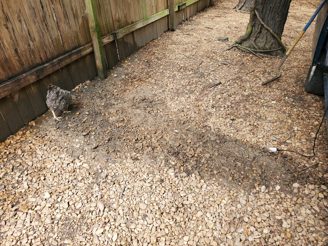 Power cable buried in trench with just the plug protruding from the ground. I'll have to come back over this with fresh gravel later. Again, with the power now established, I'll turn back to the water line, getting the tube in the ground to secure the hose. I'll take care of that little leaky hose situation under the Mustang Chicken Coupe as well. I also have to seal a hairline crack in the bucket reservoir that I also just discovered, otherwise I'll have to find another bucket and tap it for the fittings to set up a new reservoir. I'll try to glue seal the bucket first before going with a new bucket. I don't want to have leaks all over the place as it'll rust out the floor on the van, as well as make an overall mess when mulch/shavings are laid down. The project is almost done! |
