|
After having finished up most of the floor in the cab of the body I was planning on finishing up the trap door and then finally making it to the trunk area where I can get the floors done. I had to figure out what to do for the trap door though. I still had one area left to put some metal in, the area where the floor raises up to the area where the back seat used to be. I didn't want to fill this area in yet as the opening could play a role in facilitating the installation of the trap door. I didn't want to cut into the regular floor to install a trap door as this would take away some of the floor space. I decided to use the vertical space that was still open between the floors for the trap door. I decided to weld in a piece of metal to cover half of the opening then installing another piece of metal over the other half of the opening, using hinges to turn the piece of metal into a door. I also cut the metal with a lip with which to drive a screw through to hold the "door" shut and secured when not in use. 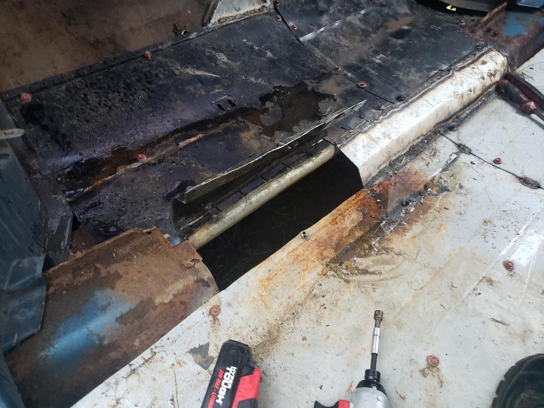 Cab trap door in place and opened up. Note metal welded in place on opposite side. 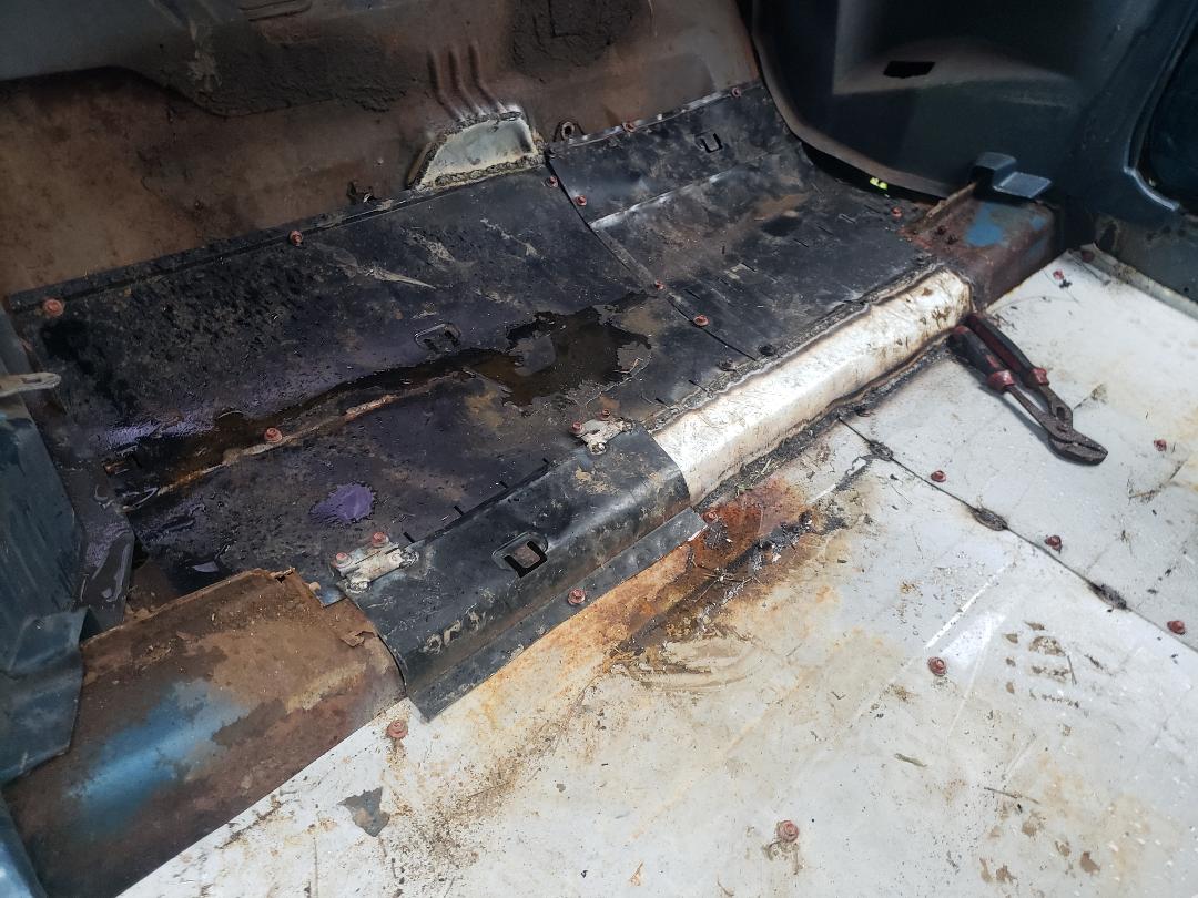 Cab trap door closed, note screw securing door in place and hinges holding door. With the cab totally done I moved on to the trunk area. I had to weld in some pipes to give me the support necessary to hold the large piece of sheet metal that I cut from a car hood. With the pipes in place I fit the large panel in place and secured it via welding and self tapping screws. With the main piece of sheet metal in place I was able to continue filling in the side areas with smaller pieces of sheet metal all the way over to both quarter panels and all the way to the end of the trunk, ensuring that the trunk floor was completely filled in. 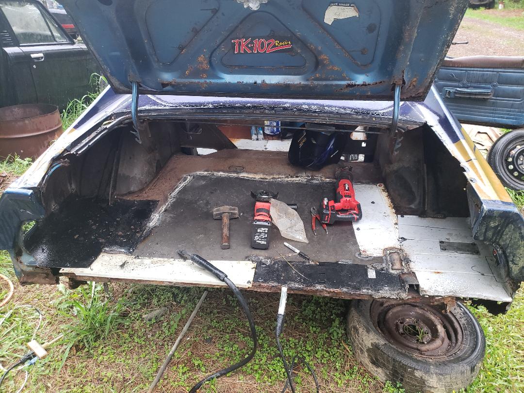 Trunk floor installed, note all the joints where sheet metal was either welded or screwed in place. Also note how the sheet metal extends against the insides of the rear quarter panels. With the floor in place I then started making plans for how to make the back wall setup. I figured that I would install a couple of doors side by side to serve as access hatches for the rear area/nesting box. Since the quarter ends are curved in a way that doesn't allow for any kind of normal panel to be installed I had to cut and install a couple of extension panels from the corners, making a sort of "door frame". These of course were just a couple of pieces of sheet metal cut to fit and fully welded in place. 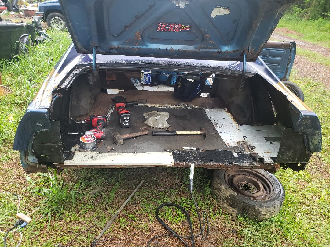 Quarter panel extensions welded in place. After welding in the quarter panel extensions I then went forward and installed a pipe across the top along the point where the bottom of the trunk lid would be when its closed. The purpose of this was to provide an extra door frame support for when I install the panels. I'll need somewhere for the doors to rest and be able to latch up to when in the closed position so the bar serves this purpose. 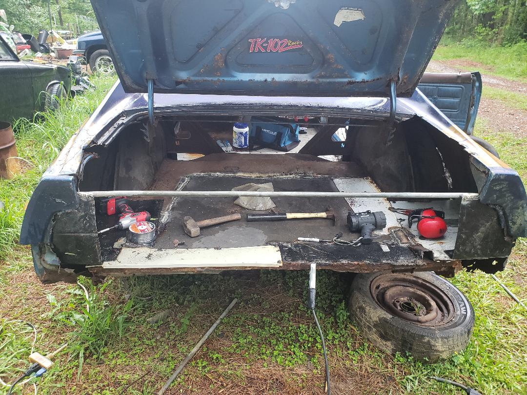 Door support bar welded in place across the trunk. Another reason for the bar was because of my plan to weld the trunk lid shut. With the trunk down the bar would be hidden from view and serve as that point for the access doors to latch to. The trunk lid is too rusty and shitty to provide any solid point to latch so that's where the bar comes in. Anyway, the trunk was welded shut. Because of the rust in spots along the trunk lid edges and the quarter panel edges where the trunk lid meets, I couldn't fully weld around the trunk but I did get more than enough of the lid secured. The rust hole openings will have to be filled in with tar just like the many other spots that need to be filled in. 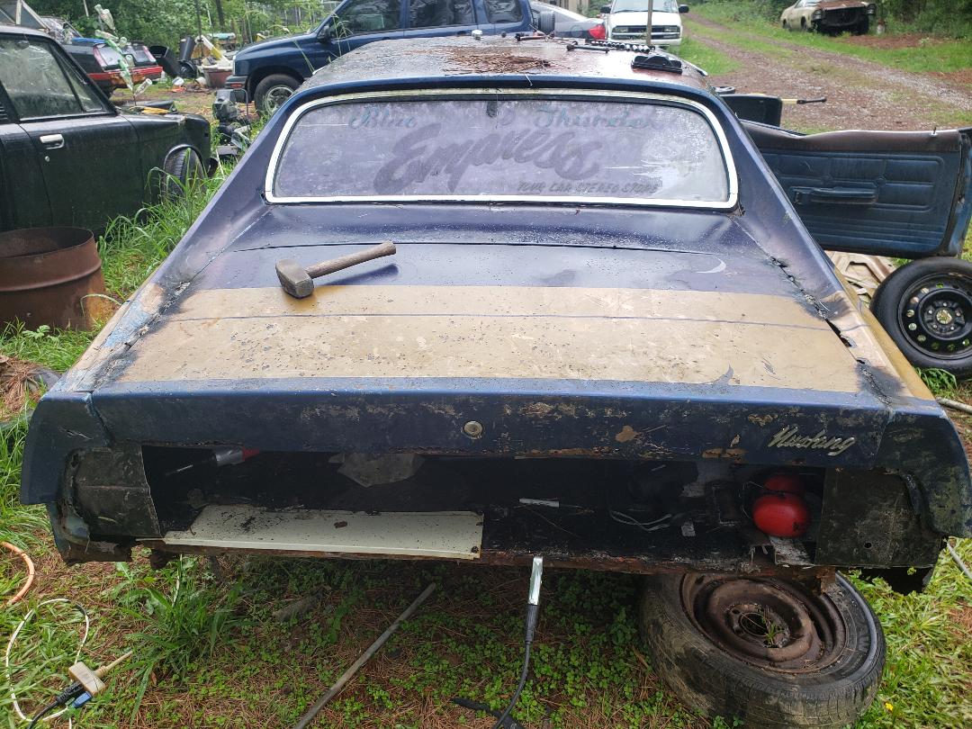 Trunk lid welded shut, note spots where no weld is present due to rust. Also note how bar is hidden with the trunk lid down. With everything down it was time for the access doors. This went easier than expected. I cut two nice pieces of metal from a filing cabinet drawer where the edges of the metal were folded up like a hem on a pant leg. These "hems" helped stiffen the panels so they would stay rigid when in place on the back of the body. I welded in some hinges to the two panels then secured them with more self tapping screws, making sure everything lined up. Upon closing the doors, I found everything lined up nicely as intended. 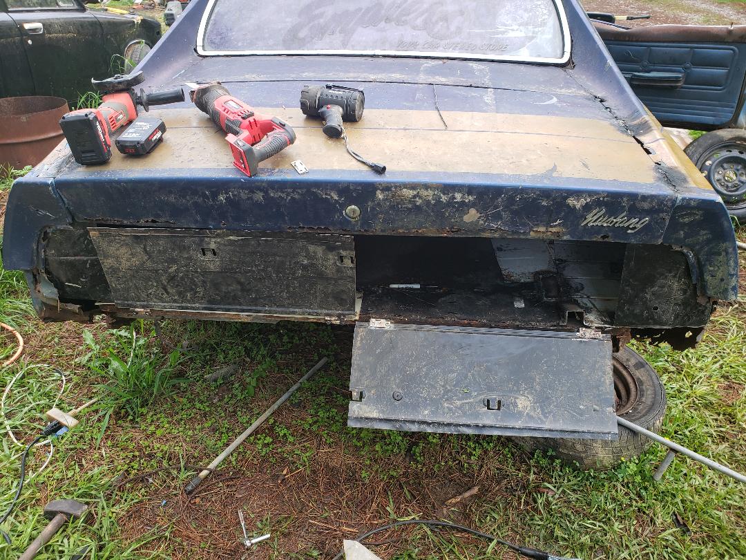 Access doors secured in place, showing one door open to demonstrate how setup is supposed to function. 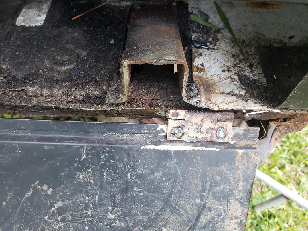 Access door hinge in place, note how spot welds are done inside of screw holes. With everything in place, the next thing is to install some latches on the access doors so they can be fully secured. I'm still up in the air about where I'd put the latches as I still want to adhere to some level of neatness. With the access doors latched the only other thing left is installing the water pressure regulator so I can hopefully slow down the water pressure in order to keep the drinker cups from exploding. Lastly there is making a metal panel for the driver's side door to fully close and cover it up then making a pipe frame to weld to the passenger door so I can attach some chicken wire to it to serve as an opening for venting the cab to the outside while still keeping the occupants secured.
0 Comments
One can get a lot done when there is plenty of time to do it. Today is one of those days. Being off and able to work on things from morning til night allowed me to get a bunch of stuff done around the Homefront, with the Mustang Chicken Coupe being at the forefront. It all wasn't a smooth ride in the beginning though.
I had run out of welding wire and was luckily able to find some at Harbor Freight the day before so I had to start things off by reloading the welder. That didn't go well. For whatever reason or another the wire wouldn't feed all the way through the feed tube. I ended up disassembling the gun down to the bare feed tube, still no luck. Some kind of obstruction or internal damage must've been present inside the feed tube. Even though this wasn't a problem before, it was a problem now. Well to cut to the chase, I was getting fed up with this damn welder. The damned thing was getting on my nerves for a while now and I've been rolling with it but not today. All it took was for the roll of welding wire to want to try and unspool some to break that final thread. I grabbed that heavy welder and chucked it out of the car on the ground then grabbed the baby sledge hammer and beat the living shit out of that welder. Well that left me sans welder. So I had to send my #2 over to Lowe's to pick up another welder. We found one that is in the same class, a flux core, 120vac powered unit. So now, while waiting for the replacement welder I had to do something productive. That something was cutting and splitting more wood. I dragged out the splitter and the chainsaws and went to work. After a while I managed to split a good chunk of wood, enough so that I had to drag more pallets from the decaying scrap pallet pile to set down for the new stacks. Even though these pallets are shitty, they will do the job since they too can be used for firewood once cleared of the regular firewood. 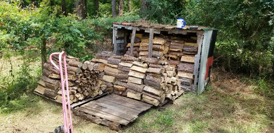
Growing firewood pile
The welder that we ended up getting was a low $200 model that Lowe's carries. It's actually pretty cool. Its smaller than the old unit and much lighter. The only drawback is that being smaller means it can't accommodate the large 10lb wire rolls that the old unit used. While I was getting those wire rolls pretty cheap online, I did manage to find bulk deals on the 2lb wire rolls that this unit can accommodate so all is not lost. 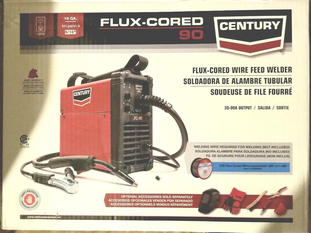
New welder
Along with the welder I also got the PVC 1/2" to 1/8" tees that I needed to install the new drinker cups in place. First thing I did do was try out the welder by installing the floor pipe for the 2nd section of floor then screwing down the sheet metal floor panels to cover the floor. The welder was used to lay a few burns in spots to fully secure the panels down. That welder is awesome. It lays down nice beads and even on the low setting it was able to more than burn through the sheet metal that I used. The old welder was hardly able to do that. 
2nd section of cab floor done. Note welds to smaller panel in foreground.
After getting the 2nd section of floor done I moved on to the drinker cups. I assembled the multiple cup assemblies before gluing it all in. Everything went in smooth and easy. I hooked up the hose and even on the low setting the water pressure was still a little high that I had some hiccups that had to be ironed out and for some, weren't fully ironed out. The drinker cups do work but with the pressure in the water lines, had a couple of issues where a drinker cup popped loose or wouldn't fully shut off. I'm awaiting a pressure regulator with which to use to get the water pressure down to a level that'll allow the drinker cups to work as intended. 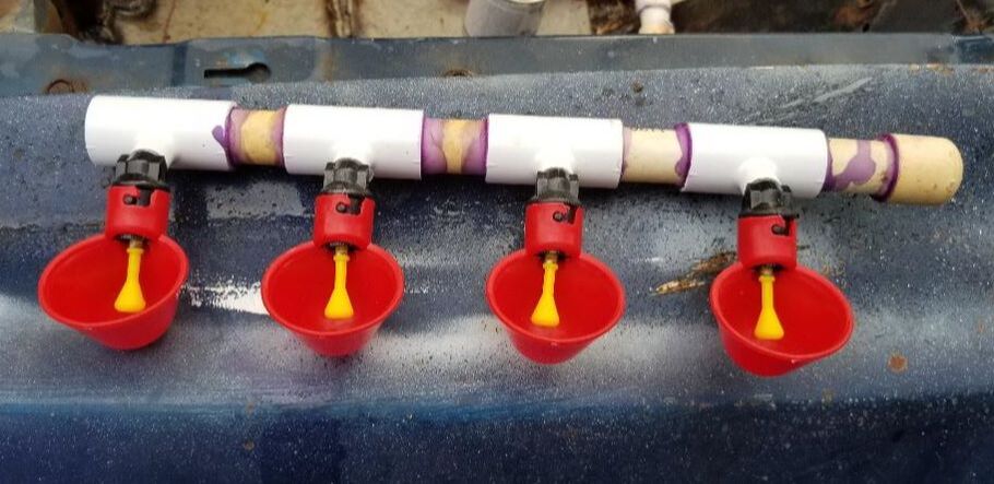
Drinker cup assembly ready.
Brooder section drinker cup assembly installed
Cab drinker cups installed.
Now back to the cab floor. I went ahead and welded in all of the floor support pipes for the entire floor so all I had to worry with is the sheet metal. With the new welder that went pretty fast. Since I used up most of the first batch of sheet metal with the exception of a patch I cut from an old car hood (which will be used in the nest box/trunk area since its got support braces still under it), I had to dig out some more pieces of scrap sheet metal that were large enough that I could cut a couple of pieces and cover a large area. 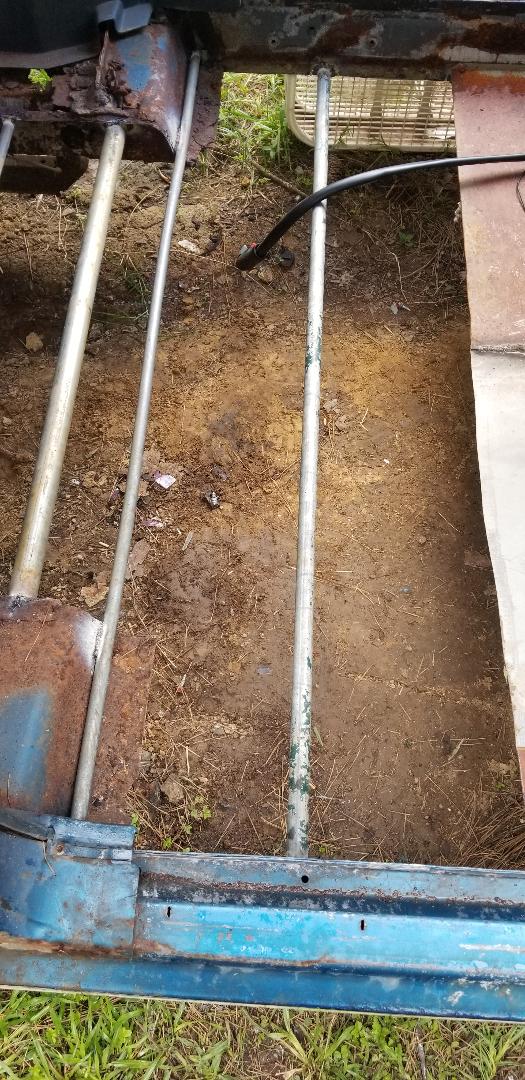
Middle section floor pipes welded in place.
Rear section floor pipes welded in.
Some of the sheet metal used for the floors was actually pieces cut from filing cabinets and their associated drawers. These panels were large enough that I was able to cover the whole middle section of floor with two pieces, one of them having to be cut short to fit the remaining space after installing the first piece. The rear section same thing. It just took two large pieces of sheet metal to cover that section. I screwed down the panels using the self tapping screws through both the remaining car metal and the pipes, and along with some welding, ensured that the sheet metal floor panels were nice and secured. All that was left at the end of the evening was a small section where the rear section rolls down towards the middle section. I'll just have to measure and cut a small piece of sheet metal to cover this section. 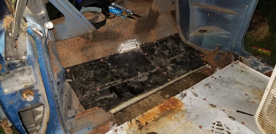
Middle and rear sections of floor done. Note red self tapping screws in different spots and the remaining opening between the two sections that has to be filled.
Once I do fill in that remaining spot of metal its a matter of setting up the refuse chute, something I thought about putting in to allow for easy cleaning of shavings by just removing a panel to expose a chute in the floor where the shavings can be swept to said hole and down a chute under the car where a bucket will be staged to catch the shavings for later disposal. Along with that I still have to make a little ramp that will allow the chickens to walk up to the trunk area where they can go nest. This project is getting done pretty fast.
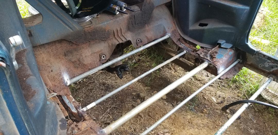
After my time in the garden I went ahead and got back to work on the Mustang Chicken Coupe. First thing I did was remove the old drinker cups that I had hooked up. Since the drinker cups are low pressure units, they will be replaced with units that screw into some PVC pipe tees that have are 1/2" with 1/8" stems for the drinker cup thread. I'm still waiting on the tees but the least I can do is prep the rest of the PVC pipe where all I gotta do is just take the PVC tees and assemble them with whatever pieces of pipe and the drinker cups so I can just make one glue joint to mate the drinker cup assemblies to the ends of the car's plumbing pipes. I used some more PVC to change the ends to a smooth piece of PVC pipe to accept the end of first PVC tee. With that done I moved on to getting the floor built in the cab of the car. I started off with laying a pipe across the back of the subframe rails I laid another pipe between the subframe rails forward from the first pipe. After welding those in I moved on to the sheet metal. 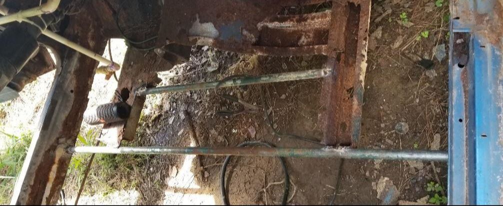 Pipes laid across cab floor area prior to laying sheet metal I did a bunch of cutting and welding on several pieces of sheet metal, I managed to get the whole first section of floor taken care of. I had to do some shaping and extra welding to take care of the transmission hump area as well as cut a slot for the PVC pipe coming up into the car from the bottom. Unfortunately I ran out of welding wire before I could finish one small patch to cover a rust hole under the driver's side floor. 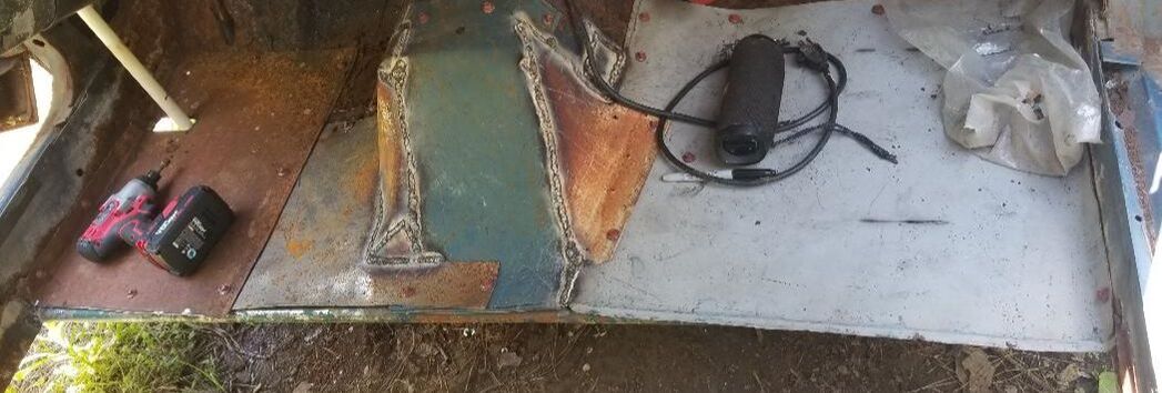 Completed first section of interior floor, note transmission hump patch and slotted panel for PVC pipe. Without any welding wire I couldn't continue with the build but the least I could do was prep some more materials for when I do get some more wire. I measured and cut several pipes to cover the span from the first section back to the rear subframes working up past the rear driveshaft hump (or what's left of it after cutting the rusty metal out). When I do get the welder back up I'll be able to get all the floor support pipes welded up so I can get the floor panels put in. Just like with the front floors I will bend the panels to allow for securing with the self tapping screws so I can minimize the amount of welding necessary to get the floor built. 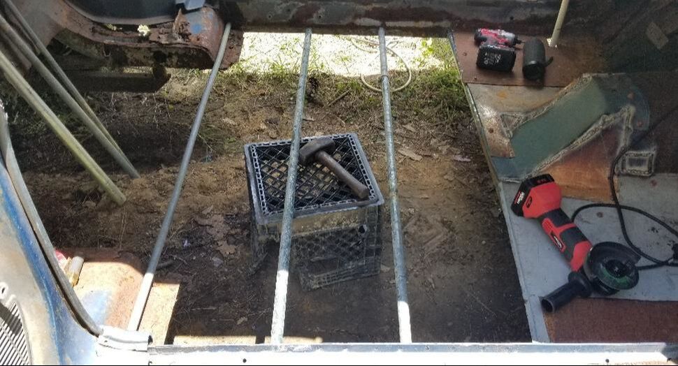 Cut pieces of pipe laid out in preparation for when I can weld them in. Extra pipes are stacked vertically to the left.
After having moved the baby chickens from in the house brooder box to two of the chicken tractors outside, the birds have gotten big enough that I needed to prep the third chicken tractor so I can split them up so they can have room to move around. One of the units has the two ducks in it while the other has the eight chickens, all of which are getting bigger.
While the chicken tractor is technically usable as is, I wanted to reinforce the bottom of the unit so when it inevitably starts to degrade from the constant contact with the ground, it'll still be sturdy for a little while longer. I also wanted to add wheels to the unit so it can be easily moved around when need be. To do this required another batch of salvage wood from the pile. After having moved the three units back into the chicken yard I had to tip the chicken tractor on its back, exposing the bottom so I can get to work. I gathered some more 2x4s that were nailed together so I can break them apart and took my measurements so I can cut up the wood to make the frame to go under the chicken tractor. 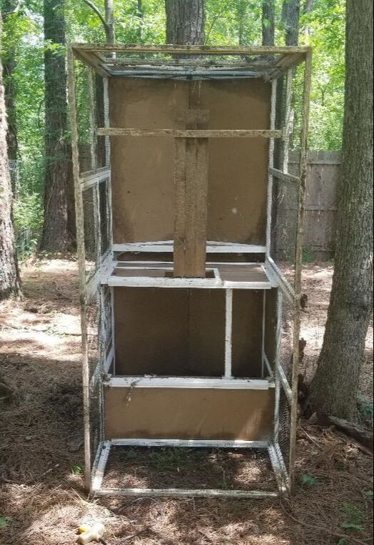
Chicken tractor tipped on its back for frame to be mounted underneath.
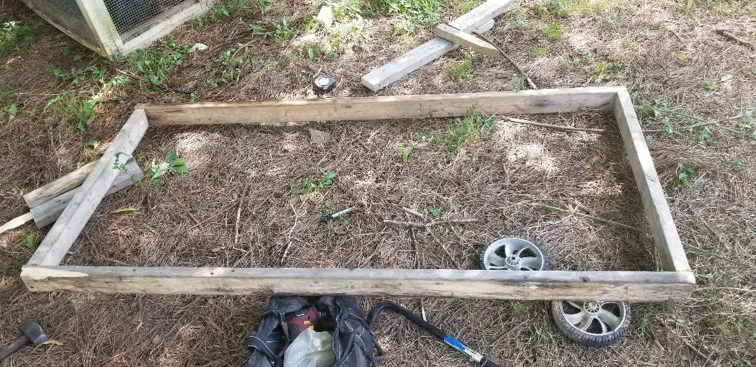
2x4 frame put together, ready for installation, note wheels in foreground.
With the 2x4 frame put together I fit it in place under the chicken tractor and secured it with wood screws. With the frame secured I then took some of the leftover 2x4 wood and cut it in half, making two pieces approximately 8" long. I then secured these in the back of the chicken tractor to the outside of the unit, but to the 2x4 frame on the inside. Of course the boards are slightly higher than the boards on the inside but this is fine for the next step. 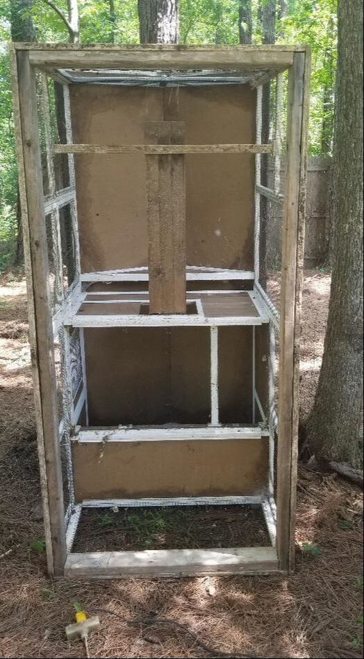
Frame installed under chicken tractor
I took the smallest of my larger drill bits that I can put into my drill, which was a 3/4" hole saw bit, and drilled a hole on either side, through both boards, from outside through to the inside. With that I took some 1/2" bolts that are probably 6" long or so, and with some washers and lock nuts, attached the wheels to the sides of the chicken tractor. With the wheels attached I then took one door handle that I was able to find and attached it to the front of the chicken tractor near the top. I will have to get another one so as to be even. With that the unit will be able to be moved around with ease and hopefully last a little longer than these things typically last when left to the elements. 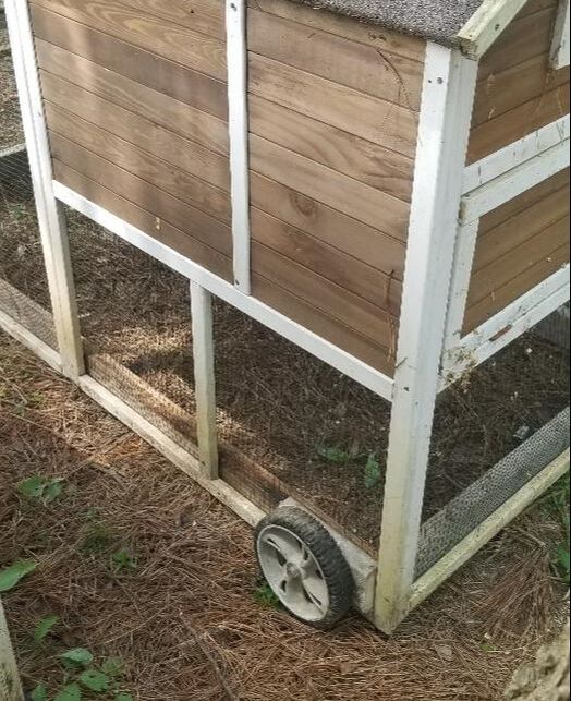
Wheel installed on back corner of chicken tractor, note outside board attached to corner.

Wheel attached to right side of chicken tractor
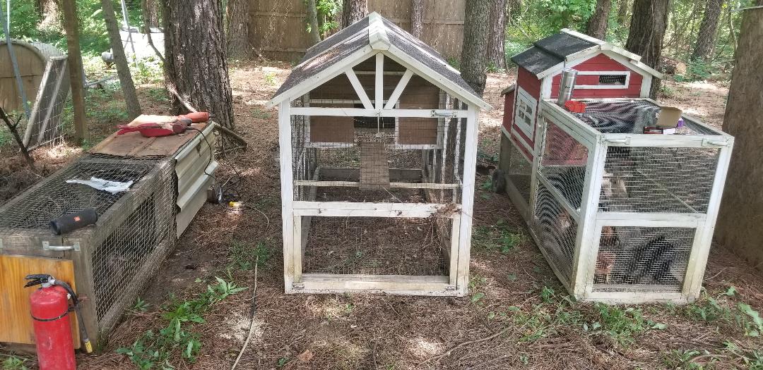
Trio of chicken tractors in place
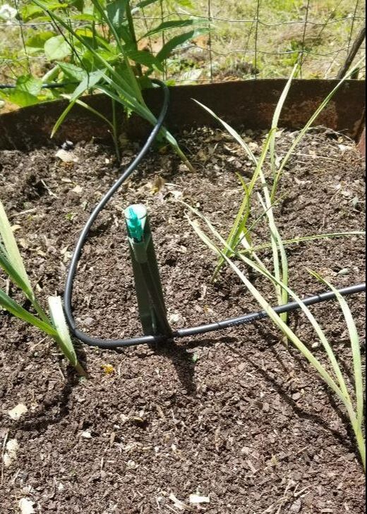
After having seen how the irrigation system was functioning with the dripper fittings getting a minimum of water pressure I decided to move the dripper lines to one of the 4 way nipples, the two new gen raised beds to another nipple, the fan shell bed and washer drums to another nipple and the last nipple goes to the two old gen drum raised beds. After getting some more hose, I got that new layout taken care of. Testing the system proved successful. Everything worked perfectly with all plants getting proper irrigation. The next order of business was the starting of the 2nd tier of the irrigation system. The old refrigerator bed housing potatoes, the drum planters and even the old raised bed housing potatoes will need irrigation. This is going to involve tapping into the main water line again but instead of just using the 1/4" poly line like from the 1st system, I'm going to be using 1/2" poly line to get a large volume of water to all of the beds. With the 1/2" line in place I'll use these tap couplings that literally just poke into the hose where needed and have 1/4" hose plugged to the couplings to go to the sprinklers as needed. First order of business though is to get a tee in place and run some 1/2" poly line along the routes where I need water to go. Again, I love this plug and play shit that this irrigation system offers. 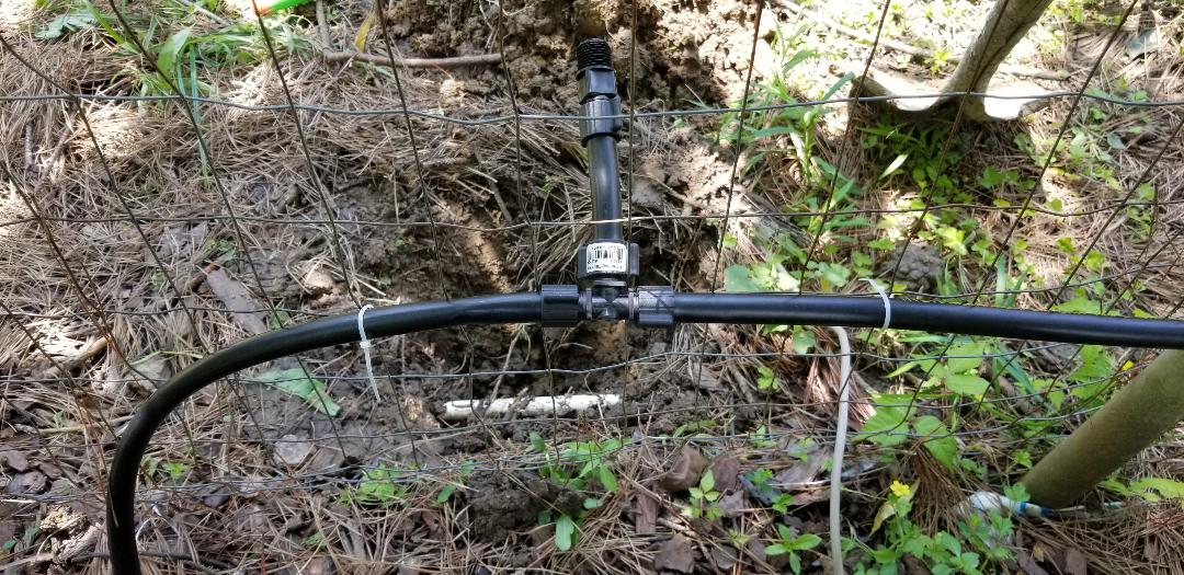 Poly line tee installed with hoses hooked up. Note water line dug up and ready for tapping. With the poly lines run, the next thing was plugging the lines at their ends. This was accomplished with a poly line/PVC adapter plug with PVC pipe capped on the threaded end of the adapter. Since I didn't have any 1/2" PVC threaded caps I had to use a combination of adapter couplings and smooth caps with short pieces of PVC pipe to make defacto plugs to thread on to the poly hose/PVC adapters. Hey, whatever works right? 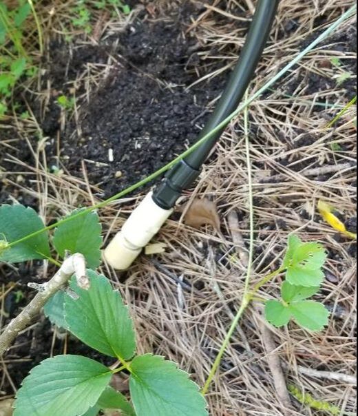 Makeshift plug for poly line running past potato bed. Note combination of thread to smooth pvc adapter with smooth cap. 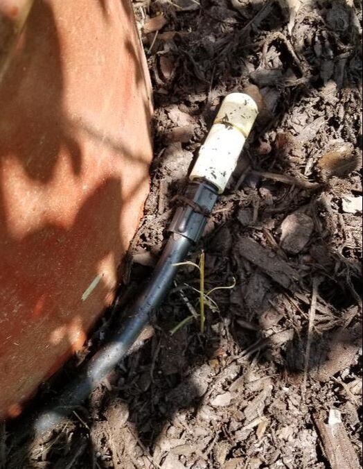 Poly line for drum planters with makeshift plug in place, made same way as other plug. With the poly lines run and buried under mulch, I started with the potato bed first. Again, using the tap couplings and a hose prick tool that is available with this irrigation hardware, I poked a hole in the poly line and installed a coupling. I then put two stakes with some 1/4" hose and the necessary tees for the mini sprayers to get the potato bed irrigation set up. Quick and easy. 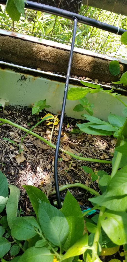 Potato bed sprinkler line tap in 1/2" poly line. Note how coupling just pokes into hole made in 1/2" hose and hooks up to 1/4" hose. Now for the drum planters. Everything went the same as with the potato bed, with the exception that I had to link together four drum planters. Each planter got one stake and sprinkler. One tap was made in the 1/2" poly hose to feed the first drum which was then linked over to the other drums using the tees for the 1/4" hose. Again quick and easy. 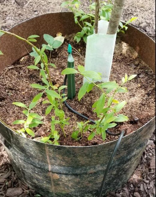 Drum planter sprinkler assembly I place. With the drum planters set up last thing was the tomato bed. I tapped into the one side of the tee that was feeding the drum beds using the tool and ran some 1/4" poly over to the bed, only a few feet away. I figured if the drum planters took up too much pressure or the combination of the drum planters and the tomato bed were too much for that side I would tap into the other side feeding the potato bed since that side only has two sprayers. The good thing about poking holes in the 1/2" poly is that there are actually "goof plugs" available for plugging up holes made by mistake in the 1/2" poly hose. Anyway, I tapped into the hose and ran the 1/4" hose over to the tomato bed and hooked up two sprinklers to cover the whole bed. The sprinklers have a coverage of 5 to 7 feet so that's plenty for this 4x10 bed.  Poly hose tap coupling feeding tomato bed sprinklers 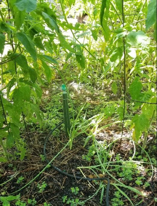 Tomato bed sprinklers in place. With the garden beds all covered, the water line hookup was next. I already dug up the water line so I had to make the sprinkler valve assembly so all I had to do was just hook it up to the water line and connect it to the poly line adapter. After cutting the PVC pipe in the ground and trimming it to give me the necessary space to put the pipe tee in, I had the sprinkler valve assembly hooked up and the poly hose adapter plugged up as well. I was able to use the manual bypass knob on the sprinkler valve to test the system, which worked beyond expectations, again. 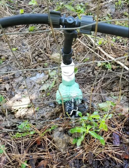 Sprinkler valve assembly installed and hooked up to poly hose tee. With the valve in place and the system tested, it was time to hook up the solenoids for both the first irrigation system and this current system I assembled. Since the solenoids are 24v, I can get away with some crude twisted pair wiring I have on hand. I went ahead and soldered the wires from the first solenoid to the twisted pair and covered the solder joints with heat shrink tubing. With that I did a shallow trench along the garden fence line over to the other solenoid and crimp capped the twisted pair from the first solenoid to the second unit AND the wires from the 24v power supply I had from our previous sprinkler system. With that I just plugged the power supply right to the power strip that is mounted on the hydroponic garden which is bein fed by its own timer. Since all of this stuff was in close proximity to one another, I figured I might as well capitalize on the available resource versus hooking up another power line an another timer for this system. 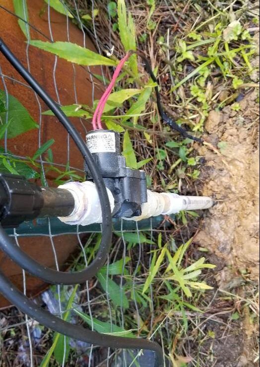 First sprinkler valve wiring hooked up and routed into the ground. Note red/yellow twisted wire pair soldered/heat shrinked and taped up. 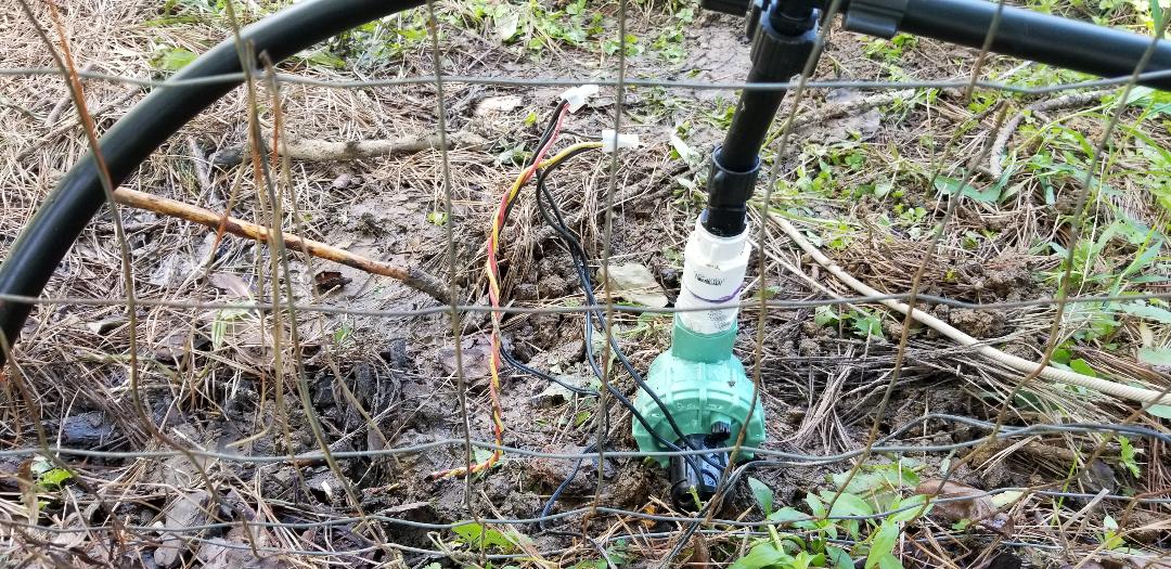 Second sprinkler valve wiring hooked up, note red/yellow twisted pair and crimp caps holding wiring together. With everything hooked up electrically and plumbing-wise, I did a test y manually cycling on the mechanical timer. Upon doing so power was sent to the solenoids and the sprinkler valves came on as intended, activating the entire irrigation system as intended. Everything got ample water. Upon checking the garden tonight I found the garden beds moist from the evening watering, showing that the system did its job superbly. When the heat of summer comes, this irrigation system will hold it down and ensure that our garden stays nice and moist regardless how hot and dry it gets. 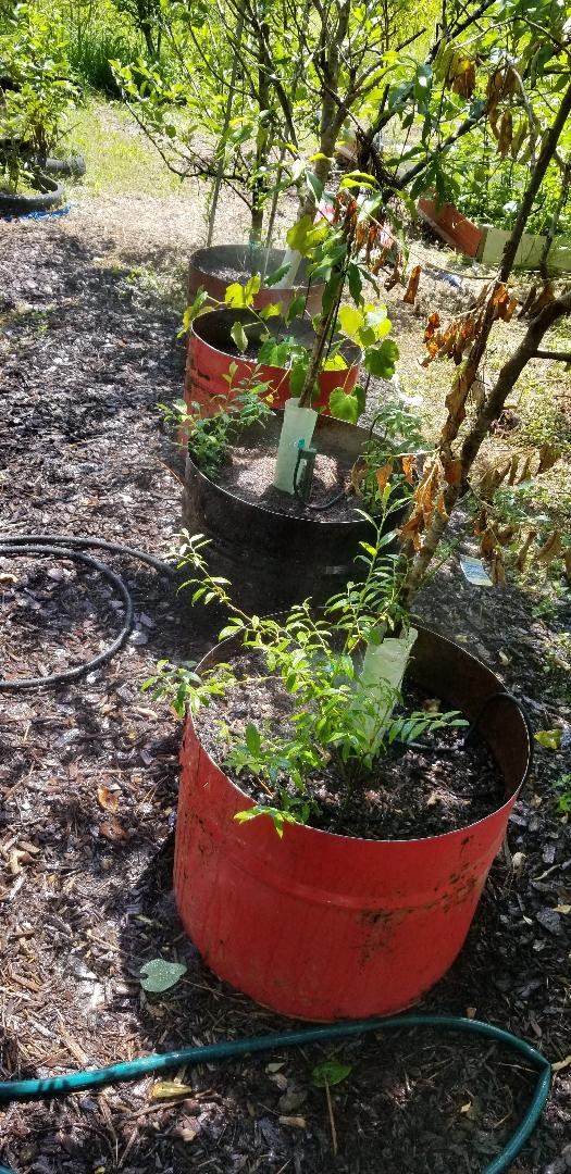 Drum planters getting sprayed nicely.
This installment turned out to be a pretty big one due to the amount of stuff that was accomplished today. A lot can get done when the time is allotted to do it, obviously. As stated before, I'm on a mission to make the garden be something that exceeds anything we've done with the garden in the years past.
First things first. I picked up a new weed trimmer from Walmart, another battery powered unit. This one shares the same 20v lithium batteries that the reciprocating saw and chainsaw use. This unit is like the chainsaw in that it uses two of the 20v batteries, giving plenty of power for chopping up errant grass and foliage. I ended up getting the unit on discount even though it included everything: charger and batteries, two spools of string and the trimmer unit itself. When I put it to use, this tool exceeded my expectations tenfold. I was expecting this thing to peter out in a short time of heavy trimming but this thing allowed me to trim everywhere I normally trim, around the house, walkways, porch, cars, garden area, even extra areas that I normally don't pay much attention to. I was able to hit wide swaths of ground with the unit, clearing grass all over. The string spool assembly has the feature where I have to bump the bottom for advancing the string as its used up. Also the string that is used is a heavy duty string so the head doesn't have to be the double string unit like most trimmers, its just one string sticking out, slicing through anything in its way. I would highly recommend getting one of these things as it combines the best of both worlds, gas trimmer mobility and longevity and electric efficiency and lack of maintenance. 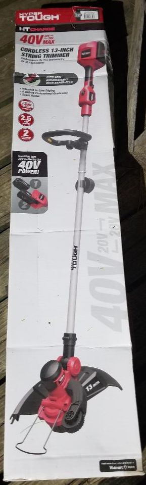
New lithium battery weed trimmer
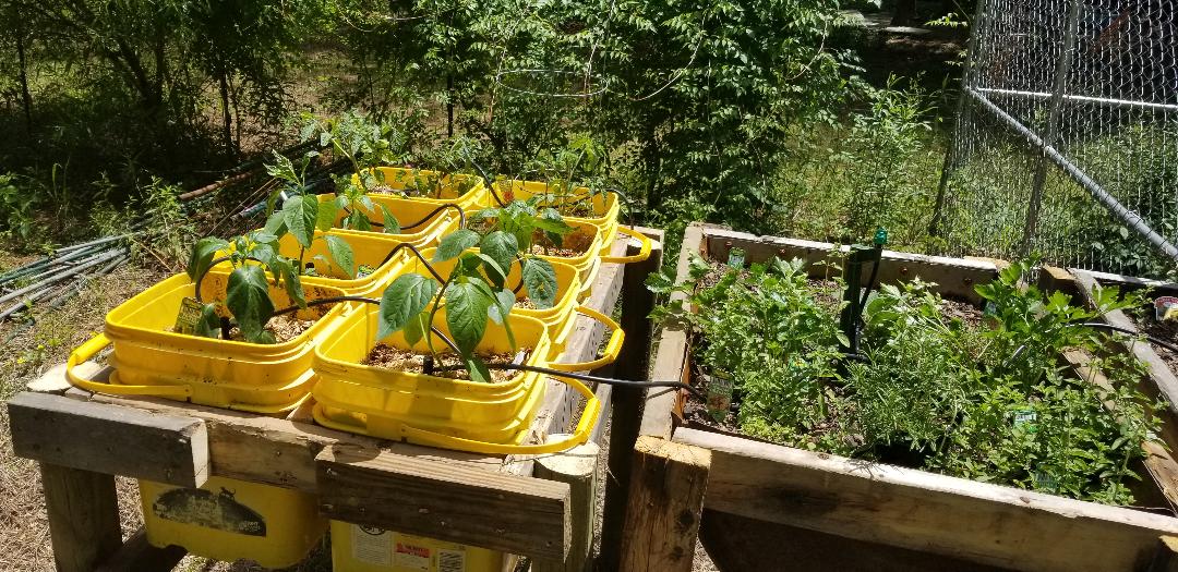
The next thing that I worked on is the building of the new raised bed that will accommodate the cat litter buckets that we planted. As usual, I gathered a batch of scrap wood from the wood pile and prepped the boards before doing my measuring. The first thing was the base frame that will accommodate the eight buckets. Next was a middle board that will help cradle the middle portion of both rows of buckets. A test fit with the buckets ensured everything fit like a glove. 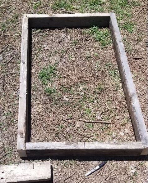
Frame base set up.
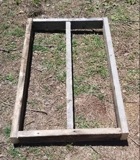
Frame base with middle support board.
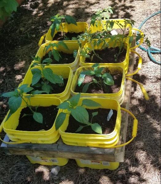
Buckets fitted to frame base.
Next I took some landscape timbers and cut 3' legs from them for the base. Using the nailgun I got the base table set up. With that came intermediate supports about a foot from the bottom of the legs. This of course will give the raised bed the extra support needed to ensure it doesn't just fall over under the weight of eight 5 gallon buckets full of wet dirt and plants. Lastly were some short 2x4 boards nailed in place around the base to further reinforce the assembly. With that, the raised bed was all done and ready to be set up. 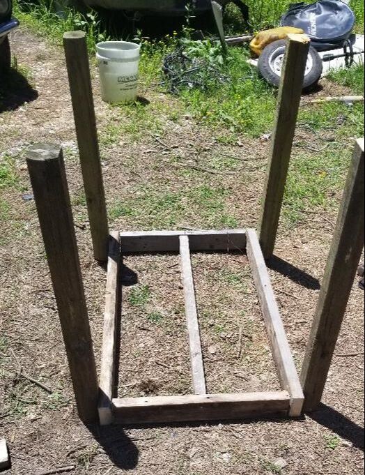
Base with legs tacked on
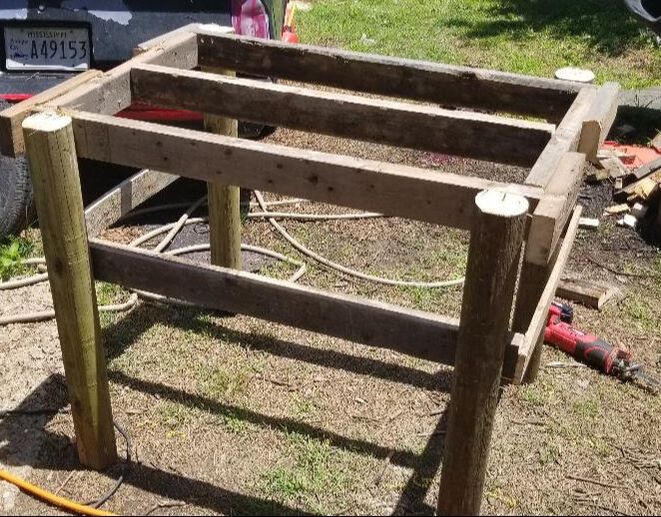
Raised bed all set up with extra supports.
With the set up being made from weather resistant landscape timbers, I didn't even bother to put the table on any bricks. The ground under the area was covered in a layer of pine needles anyway so the bottoms of the posts will be good for a while. Anyway, I took the buckets and stacked them into their spots on the table, making the two rows of four. The two tomatoes went to the back, since they will be the larger of the plants. The peppers are in the front. With the whole works set up, this garden is in action. 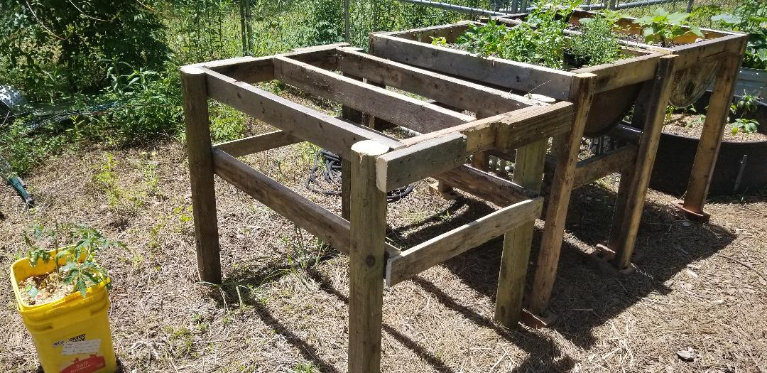
Raised bed frame set up next to other raised beds with a couple of buckets in the foreground.
The next order of business was the starting of a new irrigation system. After seeing these new "plug and play" irrigation set ups that use little drip and spray nozzles and some plastic hose that is slip on to the different fittings, couplings, tees, and the sprayers themselves. The whole setup and system is pretty easy to work with. Anyway, after doing a little looking at the components available I figured out how I wanted to set things up so I grabbed a batch of components to get things started. 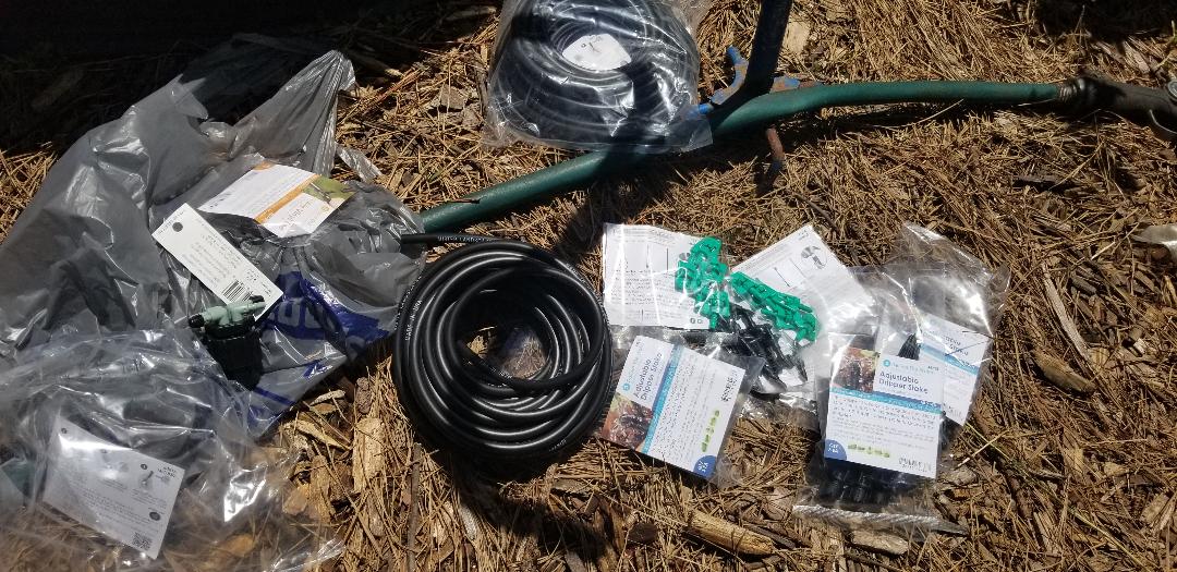
Components for new irrigation system laid out
I started off with a 4 way nozzle that screws to a 1/2" threaded PVC fitting. From here I started running some 1/4" poly hose (the hose that goes to the sprayer fittings for the direct irrigation system) to the first few raised beds. The washer drums and the old generation drum beds got the first lines. After that I ran another line over to the fan shell bed and the new generation raised beds. I used the stakes that hold the hose and the sprayers to set up the spreads I wanted in the larger beds then used these little drippers on stakes for the bucket garden. With the lines run, using two of the four taps on the fitting, I then moved on to the main plumbing feed to said fitting. 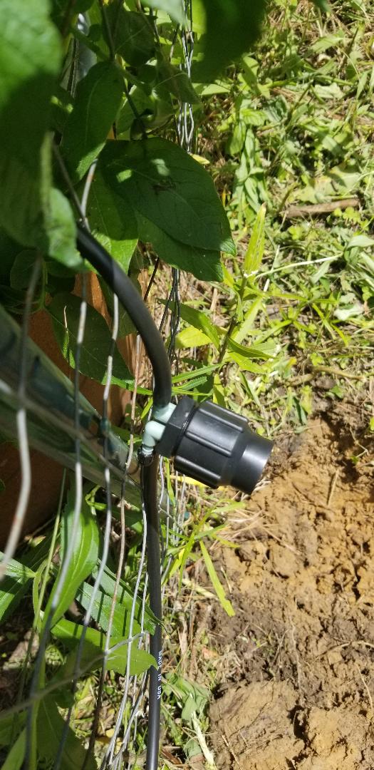
Four way irrigation/PVC adapter suspended in place just outside of garden fence with poly hose plugged to two ports.
Fan shell raised bed with irrigation stakes in place.
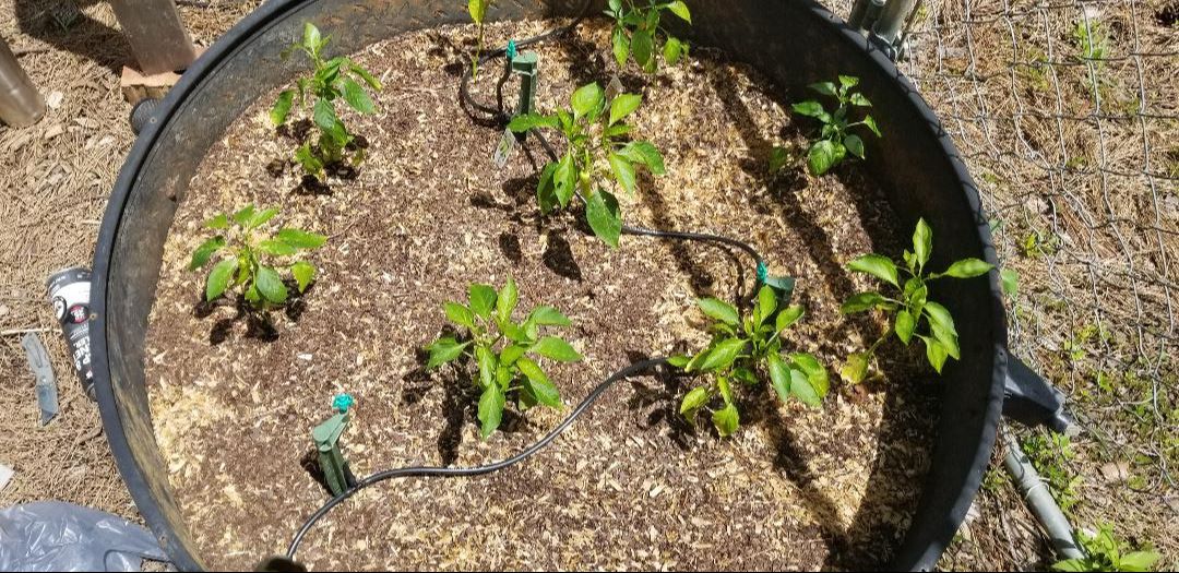
Poly tube run to stakes with little green sprayers installed.
Irrigation stake and sprinkler close up in half drum raised bed.
New gen raised beds with irrigation apparatus installed.
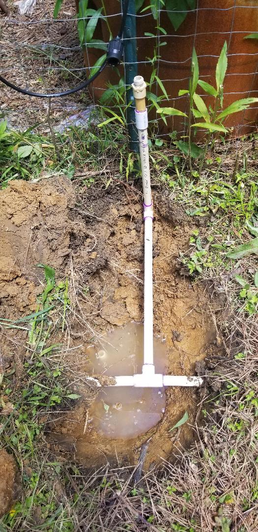
I dug up an area where I laid a water line that feeds the watering dish for the dog. This line runs from the house parallel to the garden fence back to the dog yard. Exposing the pipe will allow me to tap into the line to feed the new irrigation system. Using some surplus plumbing parts I got a tee glued into the line along with some pipe going up towards the four way adapter. The next thing is a way to trigger the water to the system. The best way for this I figured, was using the same type of sprinkler valves I used in the past for the full scale sprinkler system. In order to use the sprinkler valve I ended up having to make a modified fitting that allowed me to adapt from 3/4" smooth to 1/2" threaded. I ended up using a couple of old 1/2" threaded end caps as the outer diameter of these was just a little bigger than the outer diameter of a 3/4" bushing. First I had to drill a hole in the middle of the caps so they can obviously pass water. Afterwards, using the Dremel to sand down the caps enough I was able to glue them in place, completing the modified sprinkler valve assembly. After getting the sprinkler valve plumbed into the line I got the four way adapter hooked up and turned the water on to test this thing out. The sprinkler valve has a manual bypass valve to allow one to turn the water on manually if so desired. I turned it on and the sprayers for the washer drums and the old generation drum halves got a pretty good spray since they were closest to the feed line. The fan shell got a fair spray and the new gen raised beds got mediocre water pressure. While the first test was not necessarily a success, it wasn't a failure either. I will have to move some of the other hose feeds over to the other two ports on the four way adapter so the farther off sprayers and drippers can get a more solid pressure versus being the last in line to get any water pressure. This of course will require another shopping trip for more parts. 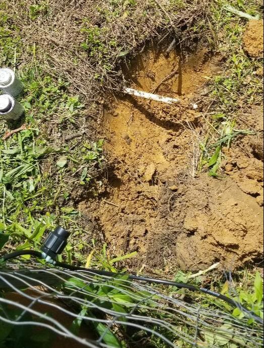
Digging up water line in preparation for hooking up irrigation system.
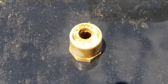
Modified end cap to be used as a bushing in the sprinkler valve.
Modified sprinkler valve set up and ready for install. Note threaded end cap glued in place as a bushing.
Water line tap set up and ready for sprinkler valve.
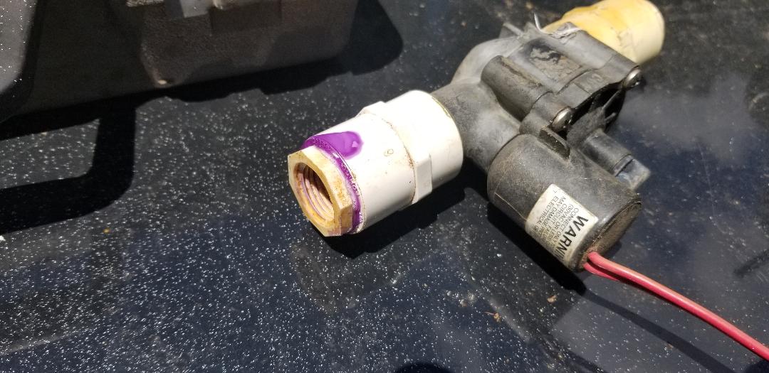
After finishing the plumbing on the Mustang Chicken Coupe only to find out that the whole setup is not really cut out for the standard water pressure of our taps. The water drinker cups are of a low pressure type, really only geared for use with gravity feed setups like what might be used with a bucket reservoir. This means I had to look for water drinker cups geared for a regular water line pressure. Well I have those on order. With that I had to move on to something else, the garden in this case.
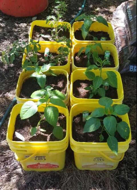
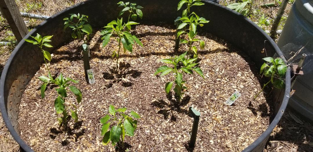
I had a few different things to address with the garden. First thing was the new raised bed project that we decided to take on. This one involves using regular buckets as planters for singular plants. In this case we have eight pepper and tomato plants. We dug out eight old cat litter buckets to use as planters. The plan is to build a base that is waist high to hold the eight buckets in the same way as the half drums to allow for easy work with the plants. 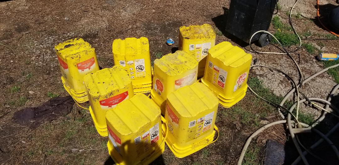
Cat litter buckets set out for use as planters.
We mixed up topsoil and composted manure like with the other planters to make a good medium for the plants. The plants needed to be put in the soil even before the whole raised bed was built, might as well give em a head start. 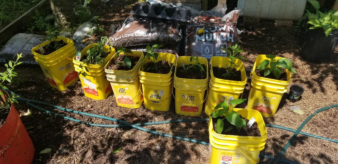
Buckets filled up and planted, awaiting their new home.
Next thing on the menu was the setting up of the outdoor timer and power strip for the two hydroponic gardens that we have set up. The power strip was already in use for the two pumps but I needed a timer to turn these things on automatically. I had some old timers I had to test to verify their efficacy, one of them being a bona fide outdoor timer with two time settings. The timer is a full mechanical unit, not digital. The settings are nothing more than tabs that are moved to the times desired and when the mechanical clock rotates the dial with the tabs to the set time, the tabs will rotate a switch to turn the unit on and send power to the pumps. When the off tab is reached it'll rotate the switch again, turning the unit off. Pretty simple and effective. Well all I had to do for this was put a couple of screws into the sides of the posts for the four tier HPG so I can hang both the timer and the power strip. With that I set the times I wanted, once in the late morning and once in the early evening. With that, the hydroponic gardens (well at least these two), are automated. 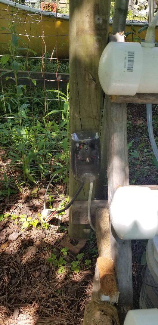
Outdoor mechanical timer mounted to post of one of the hydroponic gardens.
Power strip secured to post of hydroponic garden.
With this little job done, I moved on to the clean up of an area on the opposite side of the garden, a spot where I plan on moving the dog kennel greenhouse project. The current spot that the kennel is at has the garden at the size its always been but my plan was to downsize the dimensions of the garden by at least 10 feet. I wanted to widen the gap of the area at the back of the yard, where the dog yard extends into. Since we're using more raised beds and more hydroponic gardens, we won't need so much real estate. We can't do anything with the well established fruit trees that have been in the ground for 5+ years but there are some fruit trees that have been planted in probably the last couple of years. Same goes for some berry bushes. The same class of trees and bushes we uprooted and transferred to drums in a previous installment where I cleared an old raised bed site are the same class of trees that are present elsewhere in the garden, including in the area that would allow my moving the kennel to be in line with the new fence line I plan on setting up. I had two fruit trees to move within the area in question. One peach and one fig tree, both still kind of small so they haven't established deep roots yet. I dug out another drum and cut it in half to make two planters. Next I worked the trees until I was able to pull them up from the ground. Once free of the ground I cleared any errant weeds from the root base then planted each tree in another mixture of topsoil, composted manure and some chicken mulch. In the area where the old raised bed was, where I already set up three drum planters, I still had space for a 4th planter so one of the new drum planters went here, the one with the peach tree. I set aside the fig tree as I'm still not 100% sure where this one will go. I just wanted to get it up from its old home and in a planter so it can get itself established in the drum. 
Peach tree in 4th drum planter set up next to other drum planters in old raised bed site.
With the planters done I moved on to further cleaning up the area where the trees came from. This involved moving the old tire that was used as a crude raised bed planter as well as getting the push mower involved when it came to cutting all of the high weeds and grass within the area in question. With a little work I managed to cut the grass within the area I plan on setting up the kennel, as well as the surrounding areas at the back of the garden leading back to the raised beds and further in to where the old growth fruit trees are. I really just wanted to get a lot of the high grass cut within the areas that I plan on operating in during my garden revamp. With the grass cut the last thing I did was spread a bunch of mulch that I had several bags of along with the dirt. There were areas where old mulch washed away or because of past rains there were areas where mulch was piled up. I spread the old mulch around along with the new mulch so I could cover the bare areas, including the area around the four drums. 
Cleared area where fruit trees were pulled from. Area has been cleared for kennel greenhouse to be set up on. Note new mulch in foreground.
With the trees set up in their planters and the mulch spread out I can move on to building the frame for the bucket planters. As with the other wood projects I had to gather some scrap wood to spit up so it can be ready for separating and cut down for the base. There will definitely be more to come.
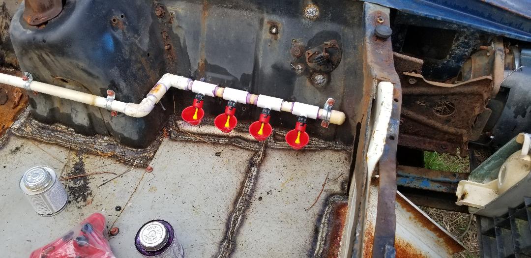
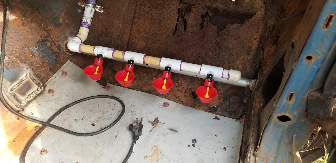
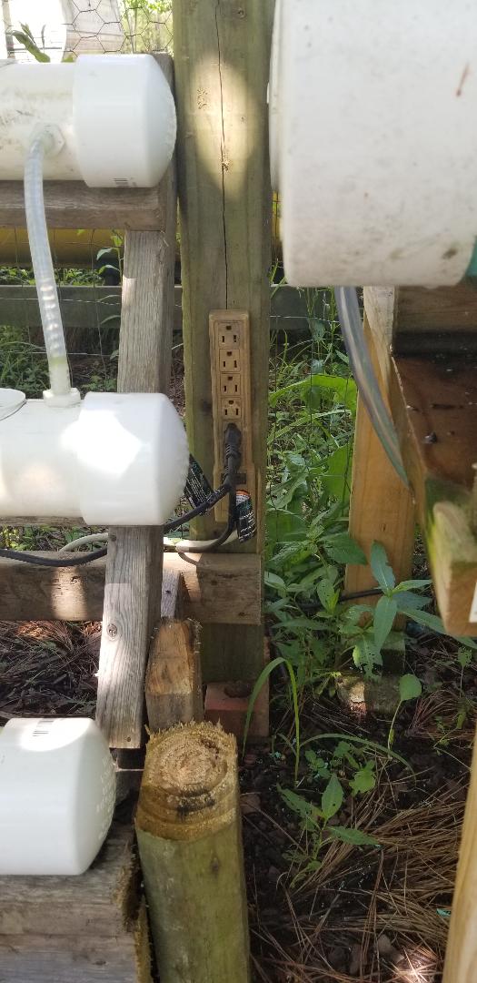
Finishing Up The Electrical System And Engine Bay Drinker Cups In The Mustang Chicken Coupe5/17/2020 After making another supply run I was able to get many things done on the electrical system and the plumbing. My intent was to get the whole electrical system done and get the brooder section of the water system hooked up, based on what I had in my supply stash. First thing I did was cut and hook up the hoses for linking the water line nipple to the nipples on the drinker cups. Three hoses and some clamps and a bolt had the whole system linked together and capped at the end, ready to accept pressurized water. This was quick and easy so t was on to the electrical system, starting in the cab, well really staying in the cab for all intents. 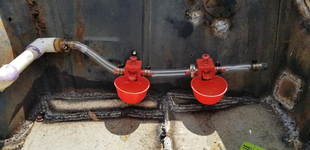 Drinker cups linked together with clear hose, note end hose with bolt plugging it. In the cab I finished up the outlet switch box that was installed under the inner dash. The cable routed to said box was prepped and hooked up to the outlet. The next thing was to run a small jumper from one of the terminals on the switch over to the hot lead on the outlet. Next move was to run a 2 conductor cable from the outlet box up the windshield and back to the brace where the old dome light was. After putting enough wire in place I wired one end to the other terminal on the switch and the other side to the neutral terminal on the outlet. Before capping off the outlet/switch box I took a length of cable with a plug on it and hooked it into the box, wiring it up to the hot and neutral terminals on the outlet. With that done I secured the outlet and switch to the box cover and screwed it to the box. 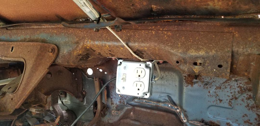 Outlet/switch box hooked up, note wire going up windshield and cable on side that goes to plug. Now for the light box. As with the other junction boxes, this box was secured to the dome light brace with self tapping screws and the wire secured in place through its associated fitting. Wiring the light fixture and securing it in place finished up the electrical system. I just needed to put a couple of light bulbs in place to test the fixtures, along with using the drill in the outlet to test those. 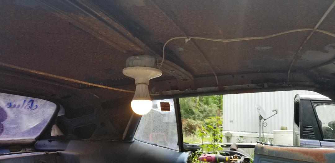 Cab light hooked up with a bulb getting power. 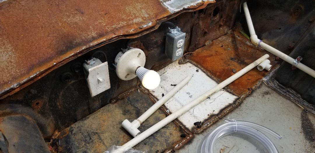 Engine bay brooder light fixture working just fine. With everything working as designed (in my head), I can now turn my attention to finishing up the plumbing in the cab. This will involve trimming the pipe in the cab and routing it to a spot farther under the dash where I can hook up some more drinker cups, but of a different design. The cups will be the kind that thread into PVC fittings that will be attached to a main water line to be neat and secured within the cab.
Now I finally get to start installing the electrical and water systems in the body. Of course I started with the engine bay as the floors are done. I had to think about where the best place would be to install the electrical boxes. I ended up deciding on the firewall as this area would allow for the heater to distribute the heat evenly from back to front. The light fixture would go next to the outlet box along with its switch. The light fixture is good on the firewall for the same reasons as the outlet box for the heater.
I started with the outlet box. Using the self tapping screws I secured the box to the firewall then went ahead and got the outlet ready for installation. Using a length of 3 conductor cable salvaged from an old cord, I hooked up the outlet and routed the cable through the fitting in the box before securing the outlet in the box. A cover finished off the whole outlet setup. Moving on to the light fixture and its box..... 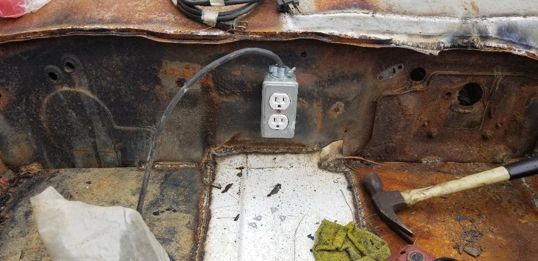
Outlet box with outlet and cable installed on firewall.
I went ahead and repeated everything with the box for the light fixture. Securing the box with the screws, I then routed the cable from the outlet box over to the light box, trimming it down before wiring one side to the terminal. I had to keep the other side open since it has to go to the switch box. The light box was also installed at a spot where a hole already existed going into the cab. This will allow me to route a cable to the inside to hook up to the outlet box. 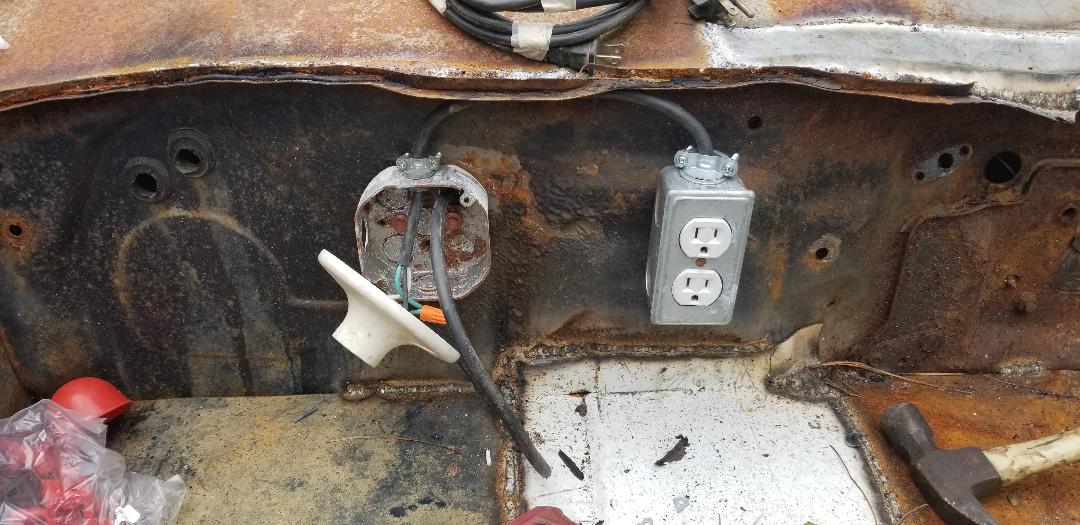
Light box mounted and fixture being installed. Note cable going through firewall into cab.
I stripped the cable that I routed through the firewall and hooked the grounds from the outlet box and the cab cable together. The neutral/white wire from the outlet cable and the cab cable were hooked to one side of the light fixture so the fixture would be in a parallel circuit in the chain, leaving the hot/black wire, to be hooked up to the switch. I installed the switch box on the firewall next to the light box and installed a 2 conductor cable between the switch and light boxes. I hooked the black wire from the switch cable to the hot/black wire that was still open. The white wire in the switch cable went to the open terminal on the light fixture. With that done I hooked the other end of the switch cable to the switch and secured everything in place with its associated cover. With that, I moved on to the cab. 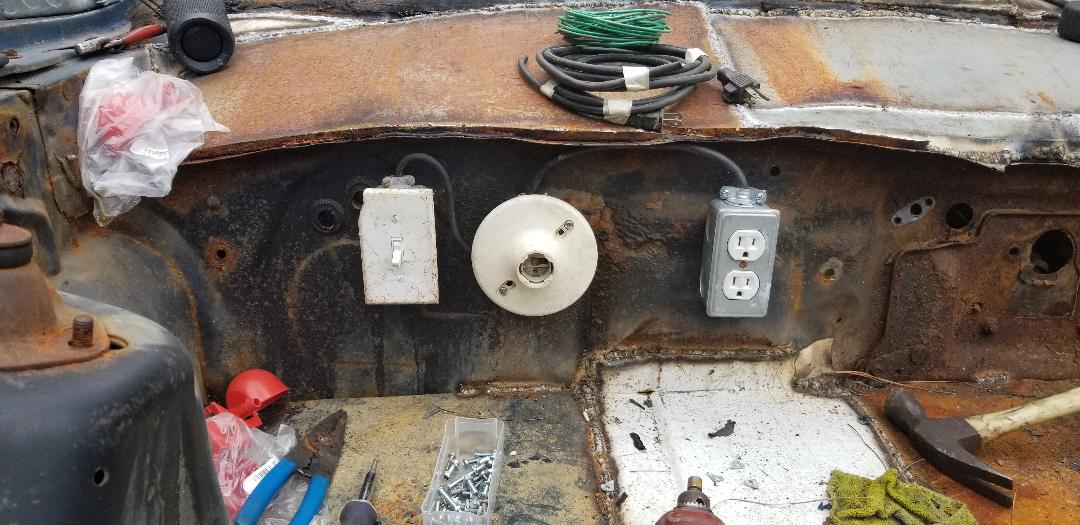
Switch and light boxes installed with associated fixtures and cables.
Inside the cab I utilized an outlet box that has tabs for nailing to a stud in a wall. These tabs allowed me to screw the box to the underside of the inner dash area which remained after pulling the dash panel and HVAC box out. With the box hanging in place, I installed the associated plugs in the box and routed the cable from the firewall to the box to prepare it for the switch and outlet that I'll install in the box to kill two birds with one stone. Rather than install two separate boxes (which I didn't have now), I installed one large box (which I did have plenty of). Since I needed to get more outlets and switches, the electrical part of this project was concluded for the day. 
Large junction box installed under inner dash inside cab of car, note cable routed from firewall through back of box.
Now for the plumbing. I had to figure out where the water fixtures will go. These fixtures are little plastic bowl shaped things with hose nipples and a single mounting point. The little valve inside the unit will automatically come on until the bowl fills with water and the weight of the water in the bowl makes the bowl lower enough to turn off the valve. I will have to test later on what pressure will be needed to keep the whole thing from just blowing open and failing. I ended up settling on installing two fixtures on the inner fender between the front of the shock tower and the radiator support panel on the left side. Reason for this was because there are a couple of large holes on the driver's side that would allow for the PVC pipe to be used to be routed between the mounting point of the water fixtures and said holes in the firewall. Using some 45 degree couplings and some short cuts of 1/2" PVC I did a short run from the shock tower over to the firewall and into the cab. At the cab there is about 2' of pipe going inside. At the shock tower I added a 90 degree coupling with a threaded end to screw in a short threaded nipple with a brass hose barb screwed to the other side. Conduit straps secured the pipe to the shock tower. From here plastic hose will be connected from the nipple to the nipple of the first water fixture. Another short piece of hose will link the two water fixtures together. I will have to put a final short piece of hose to the nipple on the last water fixture and plug it with a bolt to terminate the water line run. 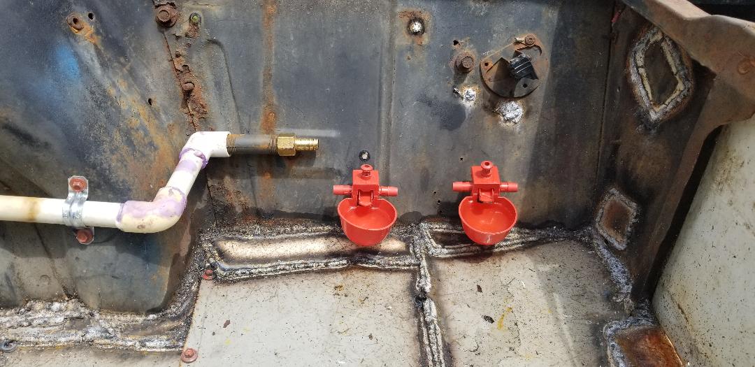
Water fixtures installed on inner fender panel next to one another.
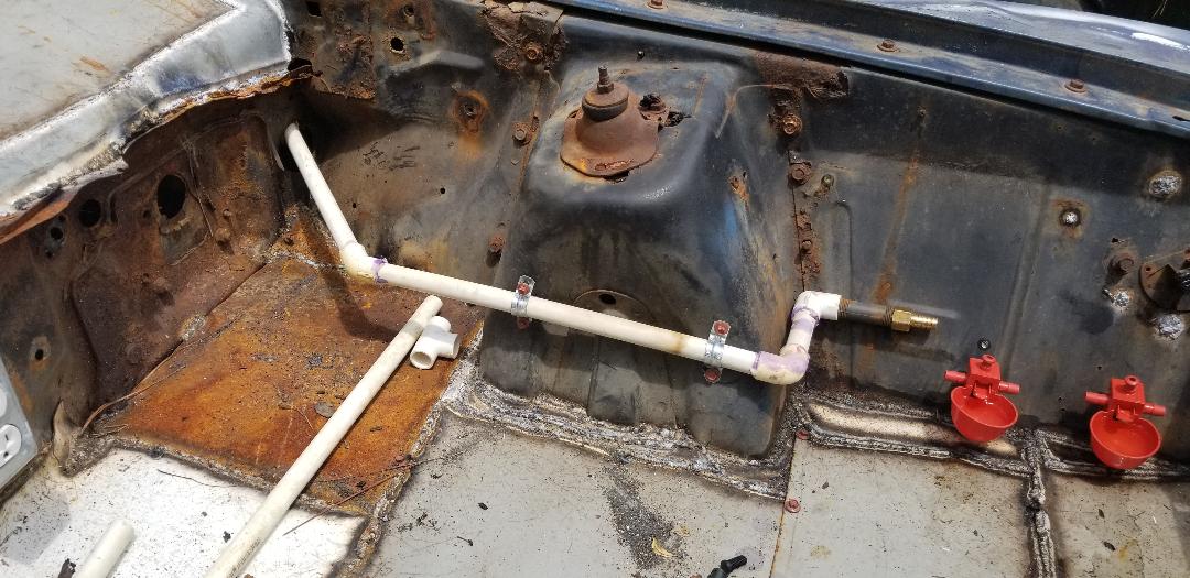
PVC water line routed between firewall and water fixtures.
I'm now in the home stretch with the brooder portion of the Mustang Chicken Coupe. I have what I've deemed the waste chute to put together, as well as welding up a cover for the rusted and cut out area over the firewall where the wiper motor and linkages used to be. First is the waste chute. To start this I measured and cut a piece of sheet metal from one of the raw scrap pieces to serve as the actual waste chute. An appliance panel, probably an old washer, supplied a piece of sheet metal with lipped sides that actually worked to my advantage. By cutting a section from the panel, I had a lip on either side to serve as the guide for when waste is swept from the brooder. The third lip was pounded flat to serve as a spot to weld the panel to the front pipe at the radiator support panel. I did have to cut an opening in the middle to accommodate the hood latch brace as well. With those few things done I had my waste chute ready to weld in place.  Waste chute panel cut up and ready to weld in. I arranged the panel where the back lip overlapped on the front pipe as mentioned, welding it in place. After doing that weld I bent the panel at a downward angle to where the panel was touching the front valance and went ahead and welded the panel at the middle groove where it went around the hood latch support. This way the panel retained its downward angle and the overall rigidity was enough to keep the panel from being moved easily. With the waste chute done the next thing was to set up the radiator opening to accommodate a removable door.  Waste chute welded in place, note how welds around hood latch support help hold the panel in its place. 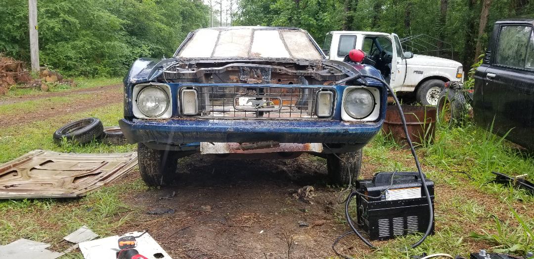 Frontal shot of car with waste chute showing under bumper and behind grille. For the tracks/guides I cut two pieces of sheet metal that were an inch wide and the length of the height of the opening in the radiator support panel. With these pieces cut I welded them in place as straight as possible. With those in place I then put the power tools to the top of the radiator support panel to cut an opening approximately an inch wide that ran the span of the opening in the middle of the radiator support panel. This opening will allow for the sheet metal panel that will be the removable door to be able to be easily removed from the top.  Removable door tracks welded in place on either side of the opening in the radiator support panel. The next thing was the actual removable door. Just like with the waste chute, I found a nice piece of sheet metal that could be cut to the measurements needed to make the door. After finding a piece that needed minimal cutting due to one of the dimensions already meeting the criteria for my door, I cut the piece and bent the last few inches of both corners on one end of the panel, to serve as tabs for easier removal. With this being raw sheet metal, until I get some kind of protective covering over the top, the tabs will at least allow for a somewhat safe removal without cutting one's hands. I will probably epoxy some fuel hose over the edges, cutting the hose lengthwise to slide them over the top of the panel. Anyway, the panel slide right in, no problem. The opening was covered pretty nicely and in turn, has the waste removal portion of the brooder finished (minus the protective coverings mentioned).  Waste chute door in place, note folded up top corners of sheet metal piece.  Waste chute door half pulled up to help show proof of concept. Lastly I wanted to cover up the large opening that was left above the firewall after cutting out the rusted metal and removing the wiper motor and its associated wiper linkages and blade bushings. This was somewhat easily accomplished as all that was really needed was to just cut and weld in a few large pieces of sheet metal. It really didn't have to be neat, just effectively cover the openings since this will cover the opening that can allow baby birds to make it into the main coop area, plus it would just be neater to cover these jagged shitty areas. I started with a good sized panel on the passenger side. After getting it welded in I cut another panel for the driver's side. The driver's side was slightly different where the inner fenders terminated at the firewall so I ended up welding one large piece of sheet metal in that was at the top, then cutting another piece of sheet metal that I actually had to cut in half partway after welding one side of the metal to the firewall. After some more cutting and welding of the edges of the sheet metal I was able to get the whole area covered up pretty good. The only thing left to do with regard to finishing up the places where metal joined metal is to seal those small and difficult to reach places with some roofing repair tar that is applied from a caulk tube. 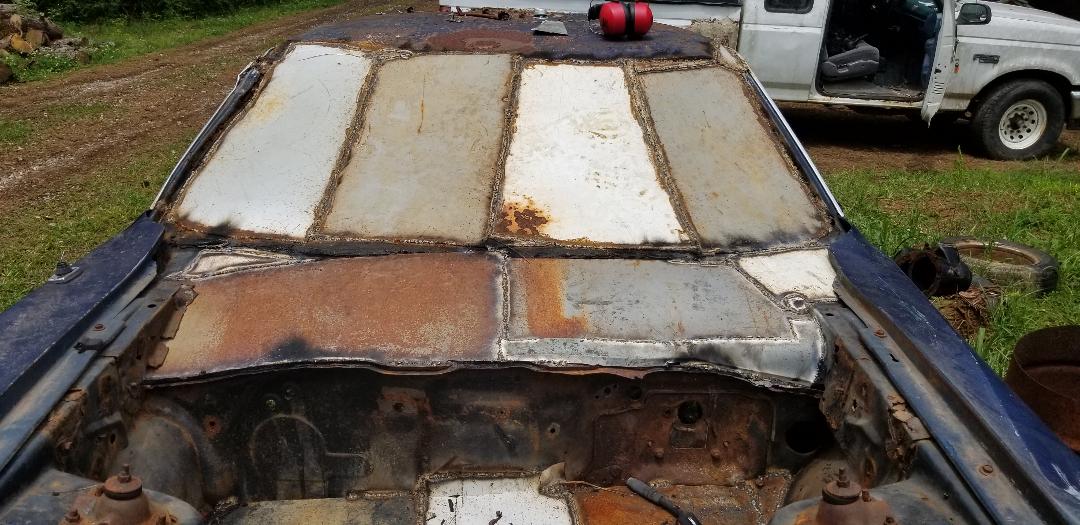 Top of firewall closed in with sheet metal to help finalize the closing in of the brooder section of the car. With the brooder section done as far as welding is concerned, the next move, as mentioned in a previous post, will be the installation of the electrical box for the heater outlet as well as a light fixture. I will check on my plumbing supply stocks and see if I can get the plumbing installed in the brooder section, complete with the automatic watering cups. I will also apply the caulk tar after getting some from the store. |
