|
As we've made note of in recent posts, an interest has been reignited with the world of air guns. With the repair/restoration of a couple models, as well as some models I've documented in the distant past, our involvement with air guns will pick up immensely in the near future. Part of that will be the acquisition of new factory made air guns, along with some plans to build air guns, including bringing back some old spud gun variants we made a long time ago, with some modifications. One of the factory made models I've just picked up is a Umarex NXG Pump Shot BB gun. This gun is built like a standard pump action shotgun and uses a slide action to work the mechanism. It uses a clip with a rotary magazine that has an internal magnet to hold the BBs in place. Ten shots per cylinder allows for some shooting before reloads. The gun is rated to shoot up to 450 fps and is powered by a single 12g CO2 cartridge that is loaded through the bottom of the pistol grip on the stock. Initial tests shown this gun to be pretty powerful, allowing me to destroy CDs from around 10 yards with decent accuracy. As much as I like this gun, I will probably get some more cylinder holder clips so I can be able to get quicker reloads versus pulling the one clip from the gun and releasing the cylinder to switch out.
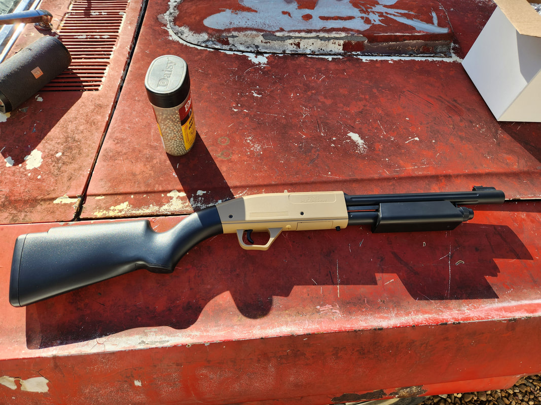
The Umarex NXG Pump Shot BB "shotgun", a nice little shooter for busting some cans or in our case, old CD's.
After my little bout of fun with the BB gun, I also received at the same time the pair of H4 7" round headlight shells, which will be going into Truckstang. The UPS guy literally dropped them off while I was shooting, so I quickly wrapped up the shooting session in order to install these headlight shells. It didn't take much to do, only having to remove the headlight bucket body panel/molding, or whatever the hell this piece of the front grill body is called. 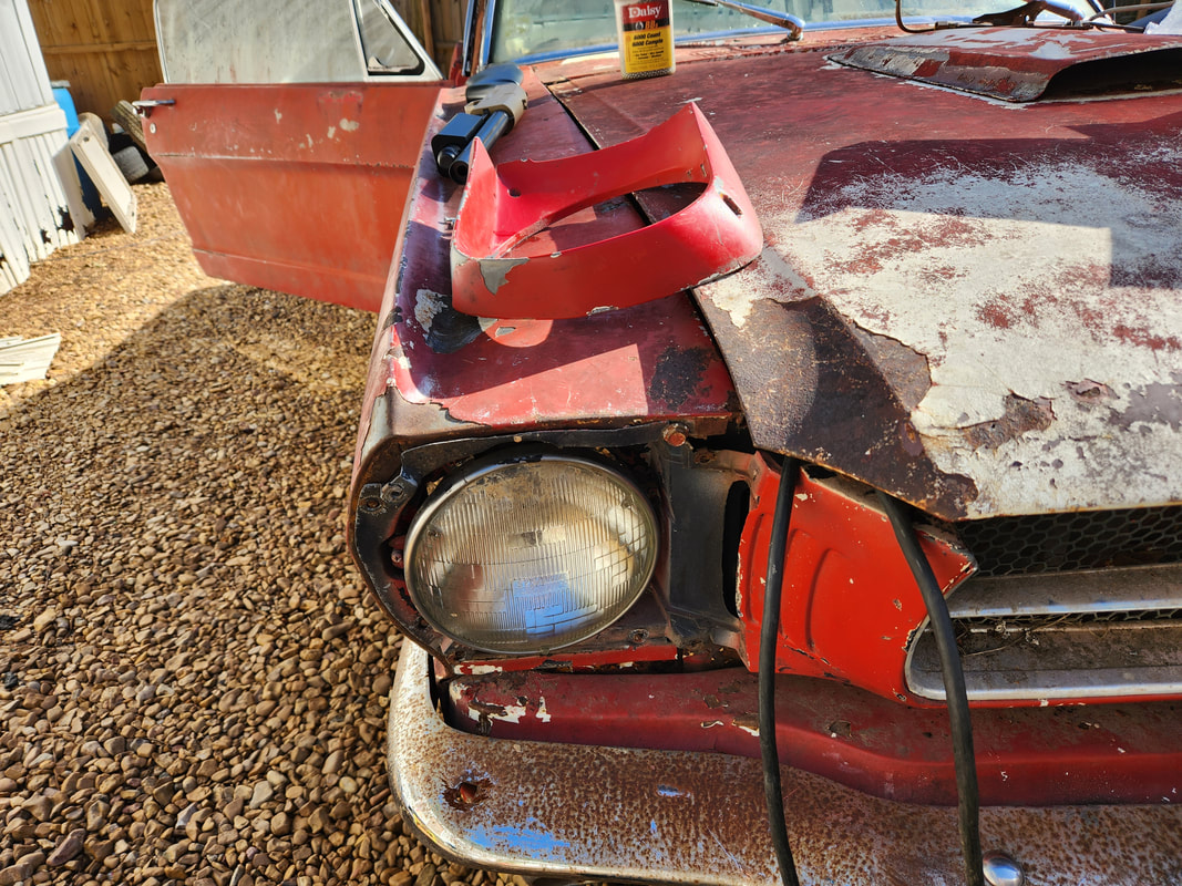
The trim panel removed from the headlight bucket, with the old incandescent bulb in place that will need to be removed.
With the skin removed from both headlights, the rings come off with three screws, allowing the rings to be rotated a little bit to remove. The headlights were already disconnected when I was testing the LED bulbs so once the old incandescent bulbs were removed, all I had to do was take the H4 bulb and install the LED bulb then seat the unit in place, replacing the ring. With the ring in, the trim panels went back on, four screws a piece, concluding the whole install. 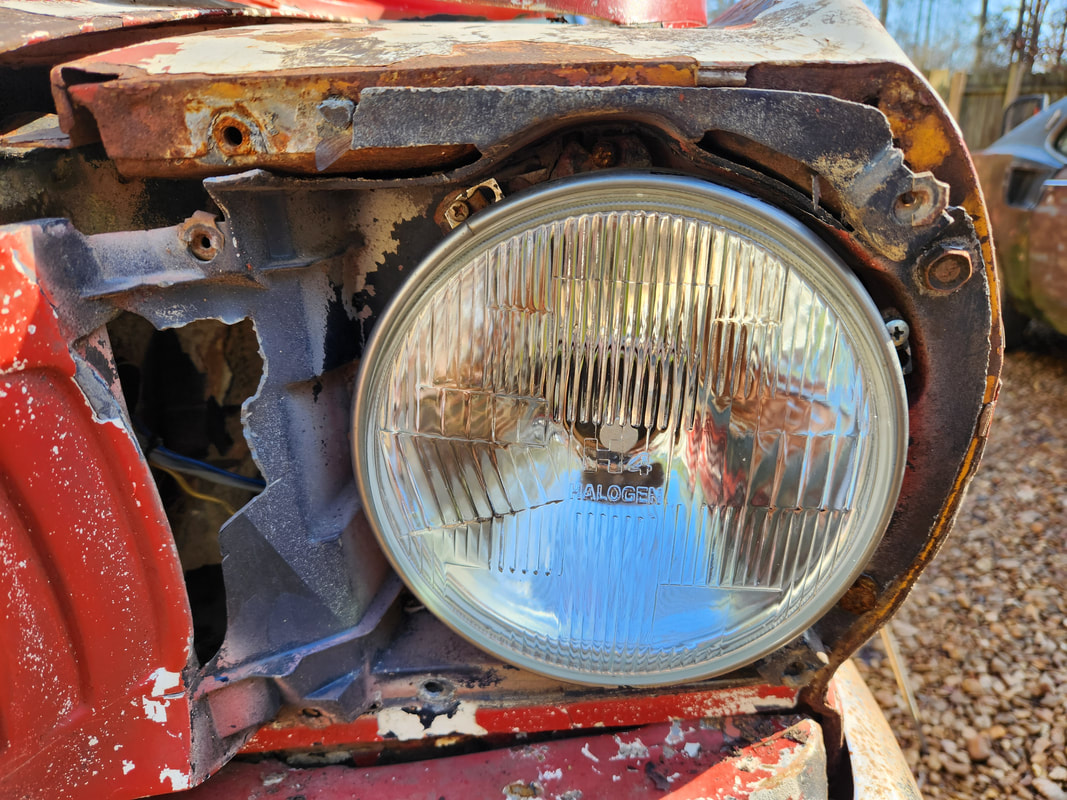
The H4 headlight shell installed on the driver's side after removing the old bulb.
A quick plug up and the LED bulbs were back to being connected. Of course everything else was in order as I had already wired up and tested the circuits front and back, well before I even bought the H4 housings. A quick pull of the switch had the new LED lights on and ready to rock and roll. With that all said and done, that is one more little component of Truckstang that can be checked off the list. 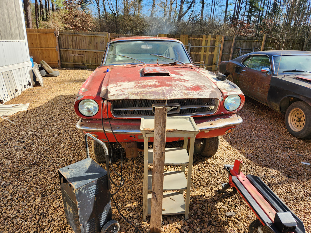
The LED headlights are on, the unit on the right side is a little dimmer than the other and with the glare of the sunlight, doesn't appear to be on, but it is.
With the fuel system pretty much done, save for the idea that I have to clock the sending unit to get it into a position where the lever will actually move in the direction needed to work the fuel gauge. In the current position, the gauge reads full when in the empty position. I'll need to apply gasket maker to the rubber seal as well to make sure everything seals since the bolt pattern won't line up. Even with that, I can technically attempt to start the engine since everything is all set, ignition, fuel system, everything. I just need to put a battery permanently in place and fill the rad with water. I'm also looking at the idea of shortening the driveshaft myself as it doesn't look too hard, there's just a few things that have to be noted for that task to be successful. We'll see.
0 Comments
After doing a bunch of work on the trunk area in Truckstang, it was time to move on to the engine bay and get that portion done on the car. I have a 2bbl carburetor that I picked up to install on this engine. Why a 2bbl? Because I had a 2bbl intake and it was cheaper to just get a 2bbl carb for $80 online than to spend $200 for a 4bb intake and another $200+ for a generic 4bbl carb. Besides, the 2bbl will be a nice little economical arrangement for the car during these preliminary trials before we move on and start throwing more money at this car to make it even more than it already is.
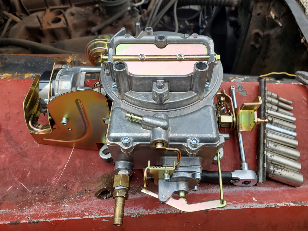
The generic 2100 substitute 2bbl carburetor that'll be our fuel squirter for the time being.
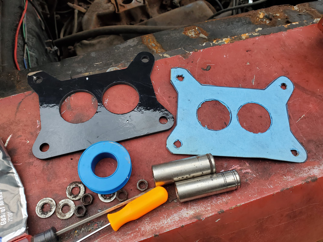
The black gasket is the base gasket for the carburetor and the blue gasket is a piece traced from the black one on gasket paper and cut out for use with the spacer to the intake manifold.
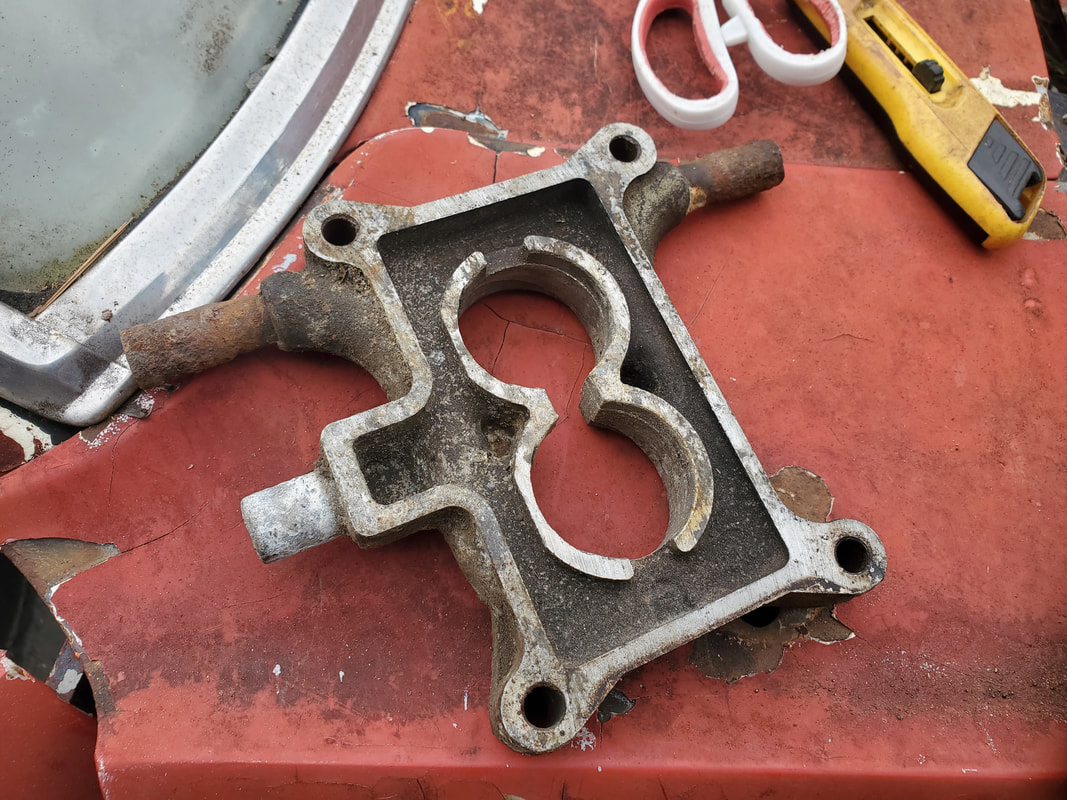
The spacer that has to be installed under the carburetor, normally used to provide the vacuum port for the PCV valve, but also to raise the carb high enough above the intake to allow the throttle levers free movement.
I had to trace and cut out another base gasket for use with the spacer that is used for raising the carb off the intake as well as provide a vacuum port for the PCV valve. Only problem is, this spacer is of a variety that uses a slightly different base for a slightly different variant 2bbl carb, so when the carb was placed on the base, there was a small gap behind the carb base that provided an opening to the vacuum passages within the carb and spacer. This had to be blocked off to close up that air leak in the making. I ended up mixing a glob of JB tank weld epoxy and squeezed it in the small cavity, then placed the base gasket on top of the spacer, with the carb smashed on top of it. After securing the carb with the nuts and washers to the studs, the epoxy was allowed to cure, creating the plug for that opening on the spacer. Of course, that plugged up the vacuum port for the PCV valve, but there is another port right on the carb that I can use. 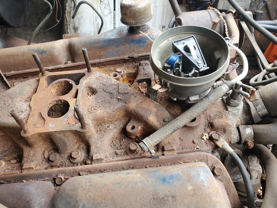
The intake base cleaned up and ready to accept the spacer, gaskets, and carb.
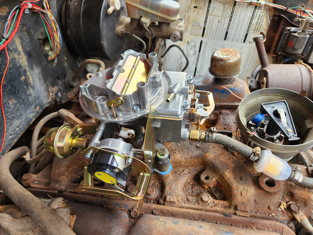
The carburetor fully secured on the spacer and gaskets, with the plug in place on the spacer to plug the opening.
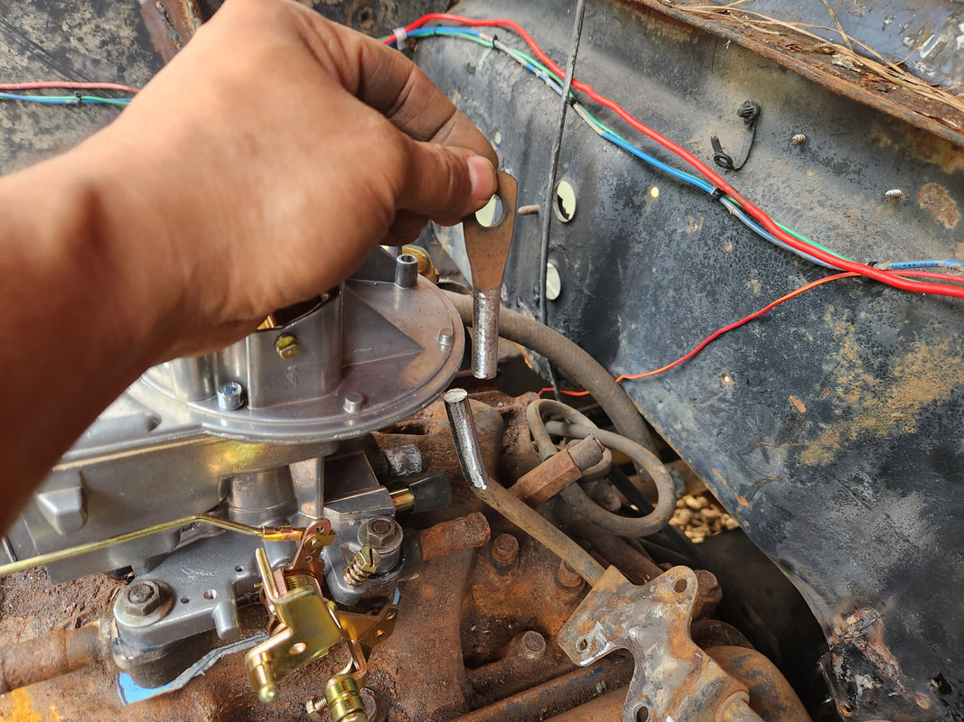
With the carb bolted down, the next order of business was the throttle. The accelerator pedal is part of a one piece lever setup instead of a flexible cable like on newer cars. The height of the lever put the loop several inches above the plane that would be required for the carburetor throttle lever. Even a test with a piece of wire showed that the throttle lever would not pull the carb lever all the way back. I ended up having to cut the throttle lever arm down, then welded the cut off portion to the side of the remaining lever arm. This put the loop in line horizontally with the lever on the carburetor. Next I took some scrap rod that had an eye bolt welded to it. I trimmed the eyebolt and a short length of the rod, then welded a short screw to the side of the rod end. I screwed a linkage end onto the screw and snapped the clipped opening of the end onto the ball on the carb throttle lever. 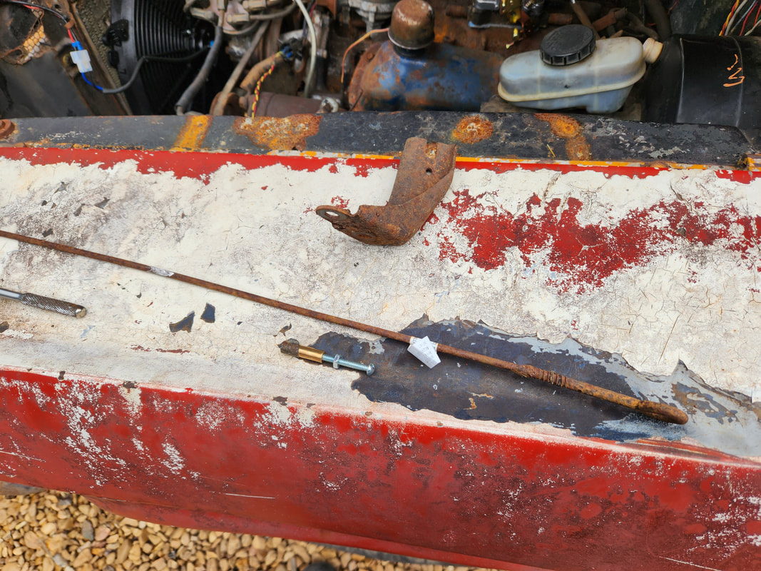
The eyebolt and rod piece along with the throttle linkage end, screwed to a screw, that will be welded to the end of the rod. The metal bracket is the throttle cable bracket that was removed from the intake, which accommodated a throttle cable.
The cut off loop end of the throttle lever, ground clean for welding.
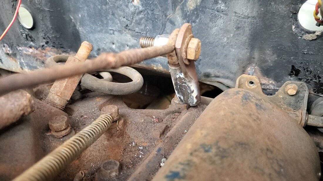
The bolted up eyebolt to the loop end on the throttle lever. The lock nut will keep everything together against all the vibrations.
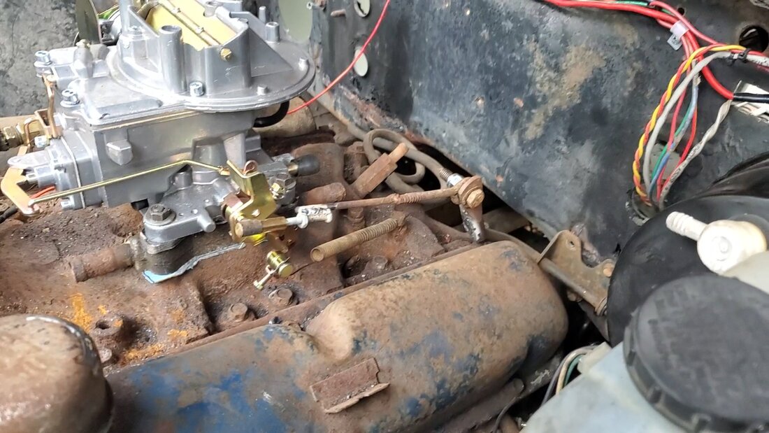
The overall throttle linkage hooked up between the carburetor and throttle lever.
With everything welded up and snapped in place, the testing of the throttle showed that the pedal will pull the carburetor throttle the full swing, allowing me the ability to go wide open throttle on the setup. There were a few other little incidentals to take care of. I took a length of rubber hose that is connected to a small manifold of vacuum hoses and routed it down to the transmission. From there I took a 90 degree hose piece and plugged it to the vacuum diaphragm on the transmission. Between this hose and the length of hose coming from the intake, I installed a short piece of metal brake hose and zip tied the piece in place. With that I have the vacuum line hooked up to the transmission. I ran a wire to the electric choke, tapping into the same power line feeding the ignition system. I also found a spacer for the air cleaner, which was borrowed from Rustang (since we're working on the Lawn Mower Carb Conversion on that car). I also had to set the timing on the distributor by finding TDC (top dead center) on #1 cylinder then where the rotor pointed is where I started the plug arrangement. With the wires all plugged up to their corresponding plugs, there's only a few things left to do before I can attempt a startup. I still have to hook up the fuel sender and gauge, along with an oil pressure gauge and sender. I have to fill the radiator with coolant to verify there's no leakage, then install a PCV valve and hose to close up that little air leak. I'll have to put a T fitting on the port coming from the back of the carb so I can run a hose to the brake booster as well as the PCV valve. It won't be long before this car's finally running, and hopefully driving.
With the fuel tank pretty much mounted, the next order of business was the filler tube and the rubber hose I would need to connect to the filler neck on the fuel tank. I ended up having to get a new rad hose that was wide enough to accommodate the diameter of the filler tube and neck. I would only use a few inches of this hose for the coupling, but so be it. The next problem that I ran into was the idea that with the tank mounted and the odd twisting of the filler tube, its very construction would not allow me to twist the tube the way I needed to in order to get the three separate components together. I ended up having to unbolt the tank from the frame rails, but the length of tubing that I welded in front of the tank ended up having to be cut free so I could move the tank forward enough in order to allow me to position the filler tube in its spot as well as be able to slide the fuel tank straight back to connect to the rubber hose. 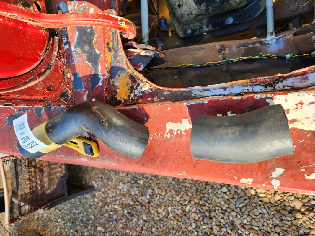 The new rad hose I had to get that was big enough to fit the filler tubes. The short piece I needed was cut free for the tubes. 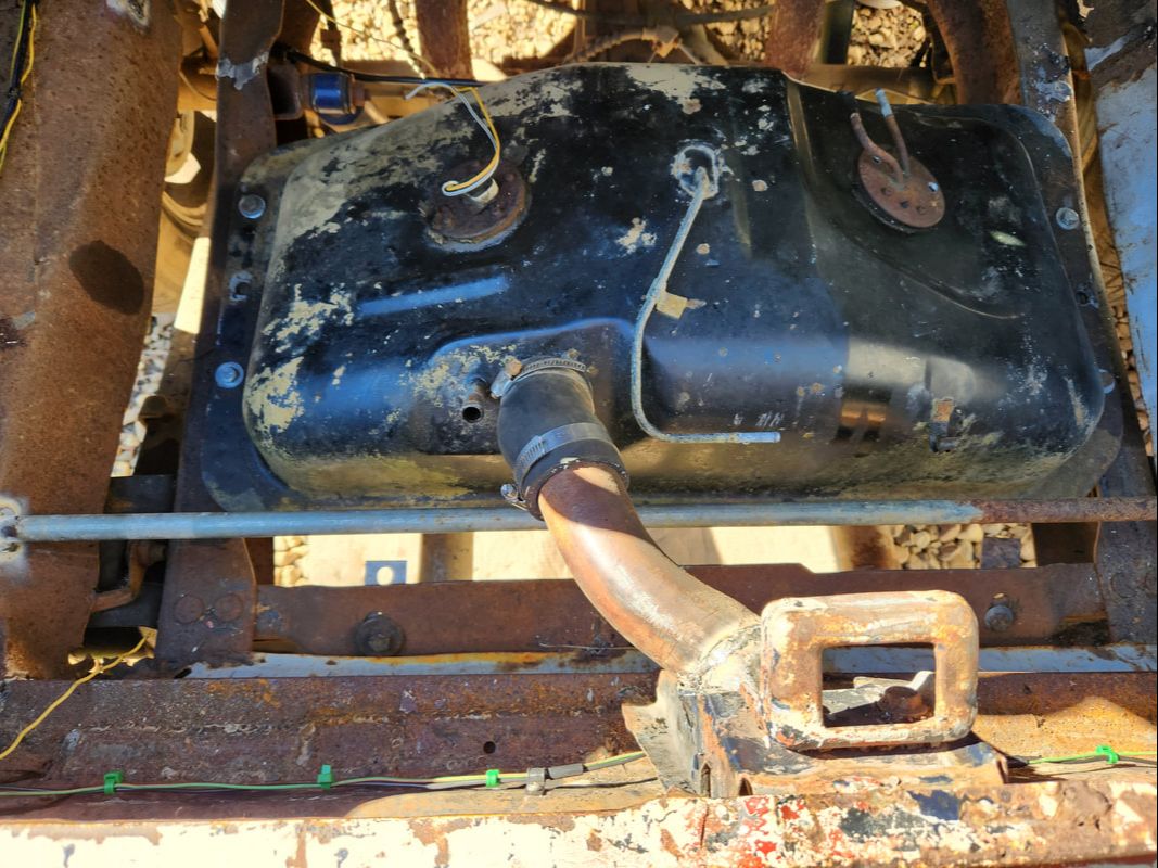 The rubber coupling hose in place between the filler tube/neck and the fuel tank bolted back in place. Note the absence of the front pipe that was welded in place. The next order of business, especially since the front tube was cut free from in front of the fuel tank, was to start making the front section of trunk floor. To do this I took a couple lengths of legging from a salvaged shop shelf and coupled them together to make the supports for the sheet metal floor. I had to cut two sections of sheet metal to make the floor, which was welded to the first pair of legs, which would be at the front of the fuel tank. I took another pair of legs and cut them to fit at the front of the sheet metal floor. To support this floor section, I drilled two holes at the backs of the fender wells and placed a long 1/4" bolt through each hole from the outside, welding the bolts in place. These bolts would line up with holes on the legs at the back of the floor panel. The front pair of legs were lined up with the internal body structure and holes drilled through to accommodate lag bolts that would hold the front of the panel in place. 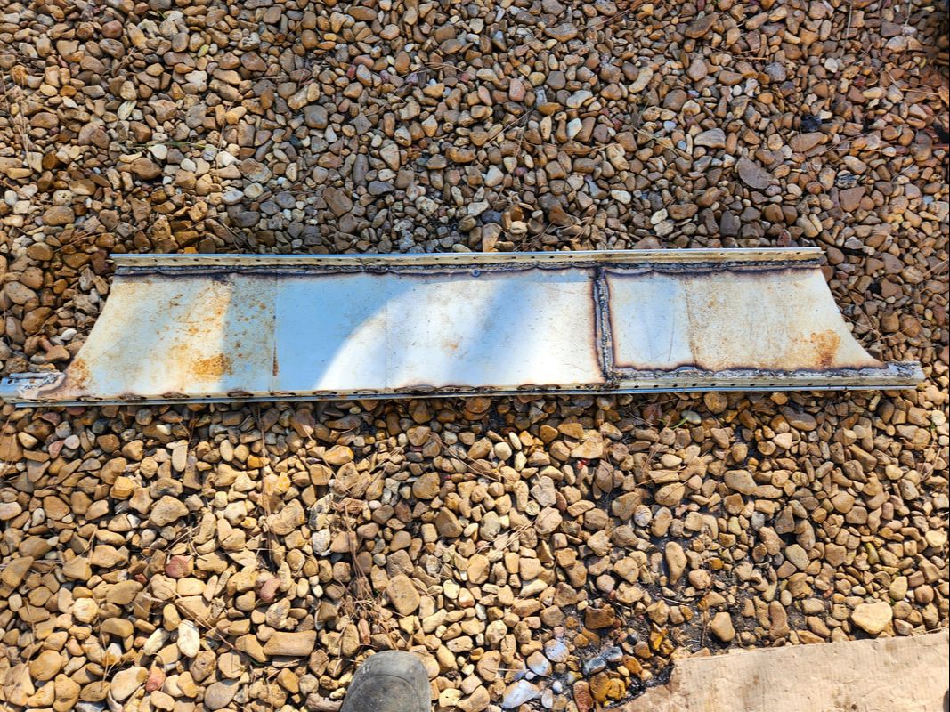 The new front floor panel section complete with sheet metal and support legs, front and back. 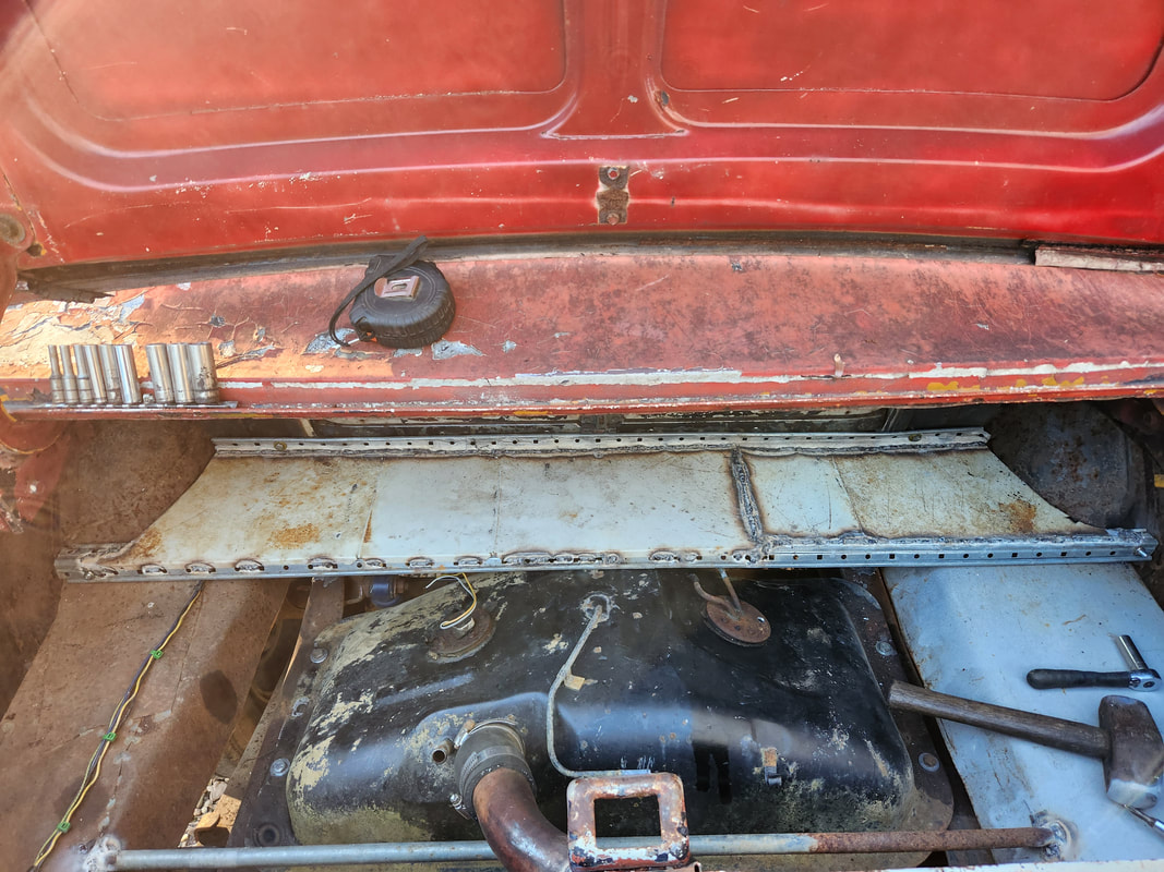 The new front floor panel fitted in place before fully securing. The panel would be slid on over the two large bolt/studs first, then the front would be lined up and lag bolts applied. Nuts would be applied to the studs to hold the rear of the panel in place. I also had to take a short piece of heater hose and cut it lengthwise to slide around the rear leg at the middle. This is because the rear of the panel rested on top of the fuel tank. The rubber hose acted as a cushion to keep the panel from vibrating against the fuel tank, resulting in excessive noise. 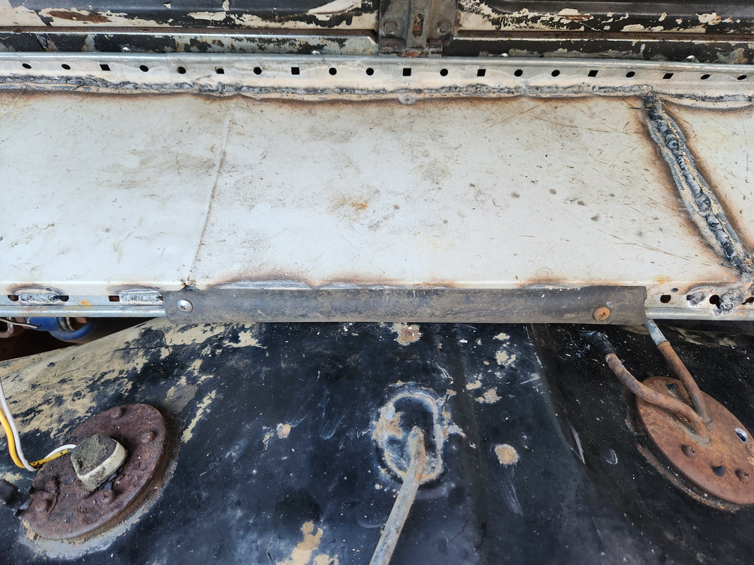 Rubber hose cut and applied around legs to serve as a cushion against the fuel tank. With the front floor all done, there was the matter of the rear floor. I already welded the pipe in place for the rear, but after looking at the spacing between the tube and the fuel tank, I decided to cut the tube free and re-weld it closer to the fuel tank. I did this since the front floor was set up to be removed, which would allow the fuel tank to be pulled forward and up and out to remove the tank. With the tube re-welded in place, I measured and cut two pieces of sheet metal and welded those in place, taking care to make cuts to fit one piece of sheet metal around the trunk latch support member. With the sheet metal welded in place, the trunk was pretty much 2/3 done. I still have to figure out what to do with the middle section that spans the fuel tank. 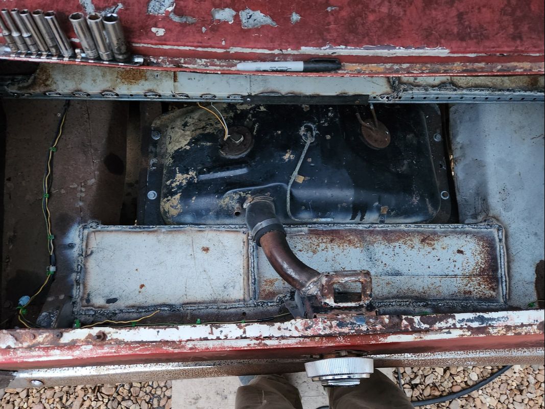 The rear section floor welded in place behind the fuel tank. Now, what to do about the middle section... On a lighter note, while welding this crap, I needed to be able to quickly cool the metal down for handling. Upon trying to fill a watering pot, I found the pot with a crack in the side. I had another pot that didn't have a nozzle, and the nozzle from the old pot wouldn't fit. So what did I do? I cut the neck from the bad pot, used a heat gun to soften the neck as I pressed it over the neck of the other pot, then removed the neck and applied hot glue inside the rim of the neck, pressing it back over the neck of the other pot. Once the glue was cured, I had a bastard pot with nozzle, ready to go. 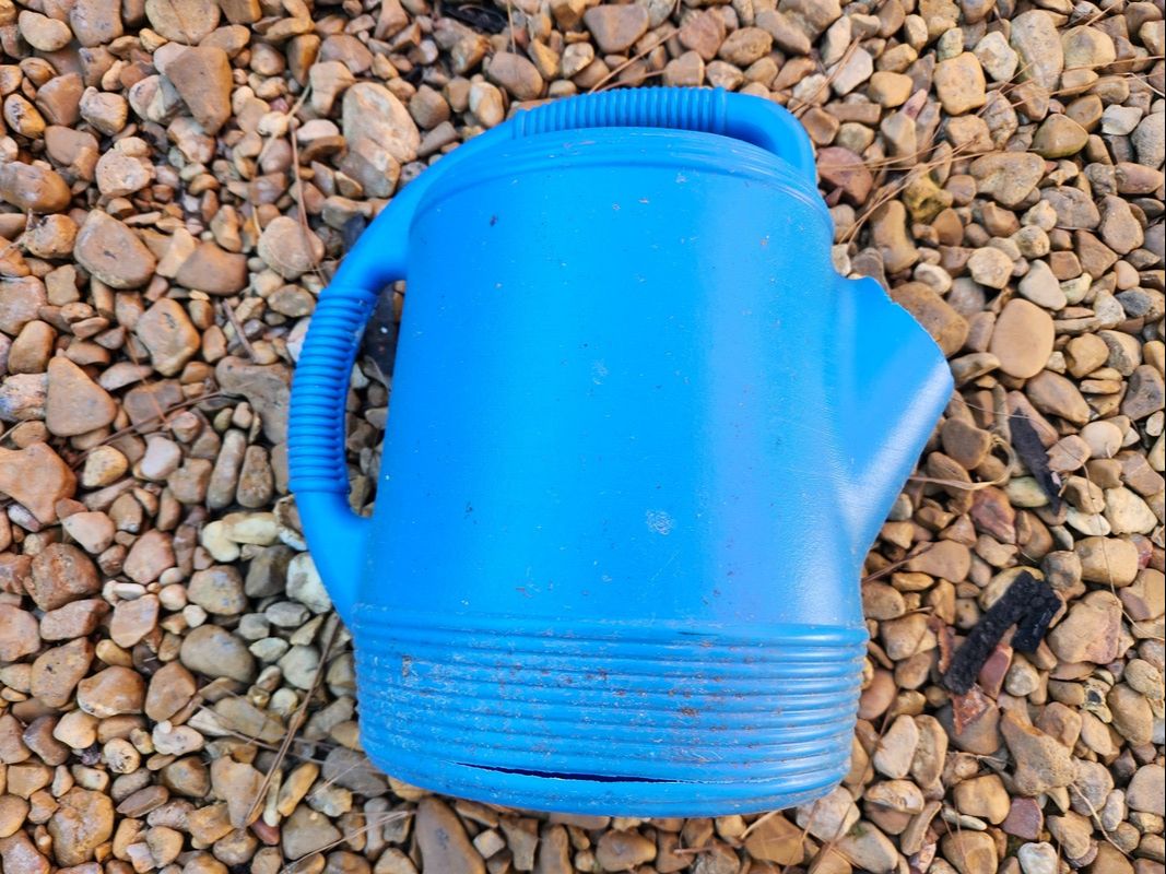 Old watering pot with crack on lower side, this is trash. Note the missing neck, cut free. 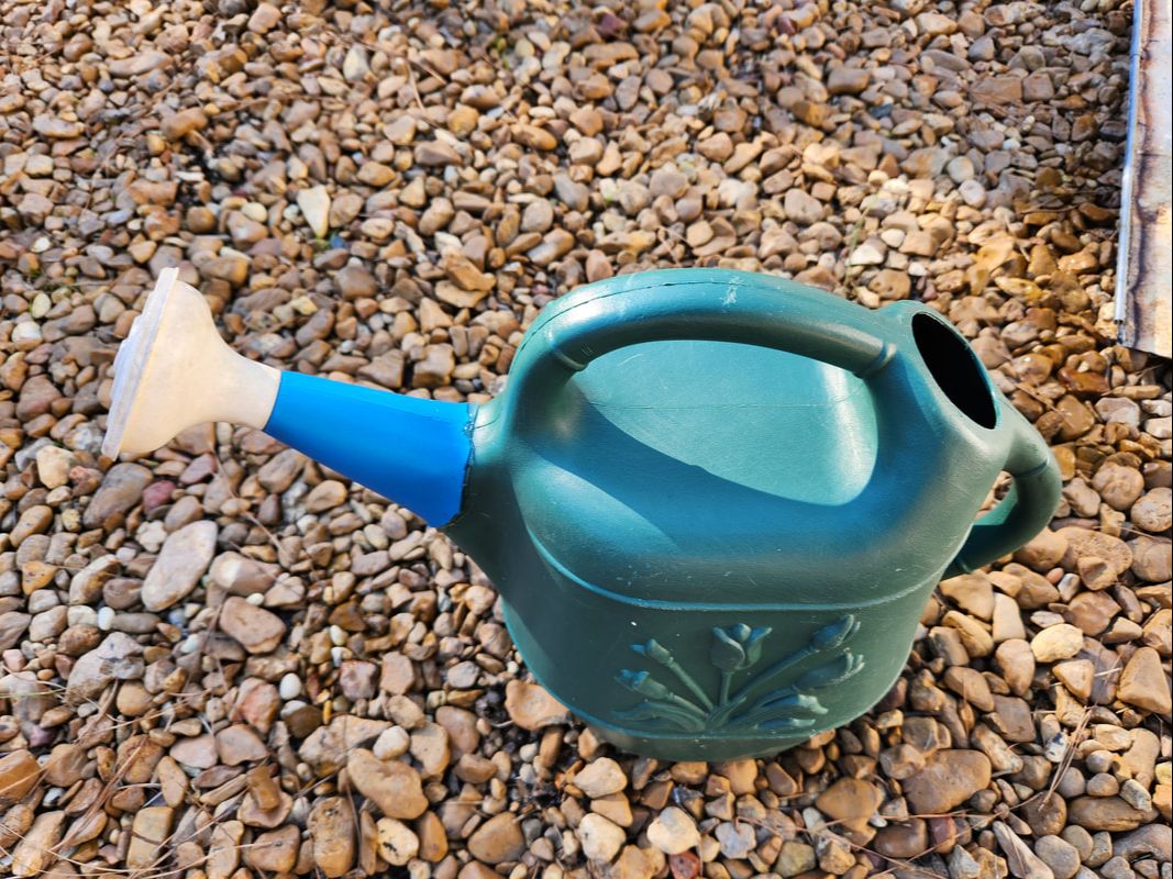 The neck here is hot glued to the new pot after being shaped with a heat gun. The bootleg repairs yielded a useable watering pot from the two pots that were not completely viable separately. For the time being, I will leave the middle floor section alone on the trunk and move forward to the engine bay to work on that part of the fuel system. The carburetor and everything associated with it needs to be installed. From there I need to time the distributor and hook that up. Once that's all done, lastly I need to address the fuel sending unit issue, whether I use the old unit or install a universal unit to coincide with the gauge I recently picked up. We're very close to getting Truckstang in operation! With the LUV fuel tank in place and ready to be secured after drilling holes through the frame rails, there were a couple little things I had to address before fully securing the tank. One, since the tank would literally be metal on metal, I decided to provide some form of cushioning, in the form of old heater hose. I did this by cutting a couple short lengths of hose lengthwise, slid the sections of hose over the frame rails, covering the drilled holes, then drilled holes through one side of the hose. 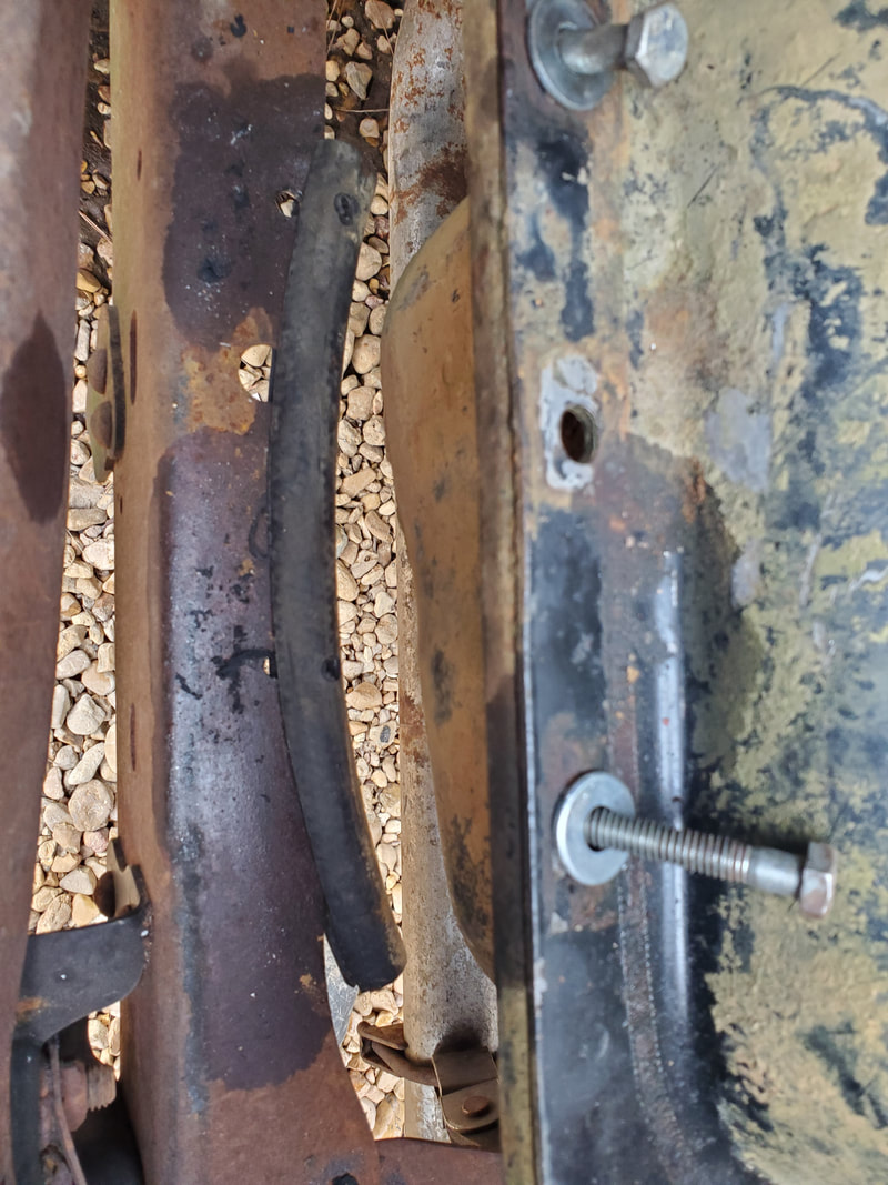 The length of heater hose cut lengthwise and drilled through to apply bolts through in order to cushion the fuel tank against the frame rails. Once the hoses were prepared, I set the fuel tank down on top of the hoses, and over the frame rails. I used some 2" long 5/16" bolts with washers to go through the top of the fuel tank and the amount of spacing between it, the hose, frame rail and the outside washer, securing everything with a nut. With the fuel tank fully secured, I moved on to another small issue, the fuel pickup unit. 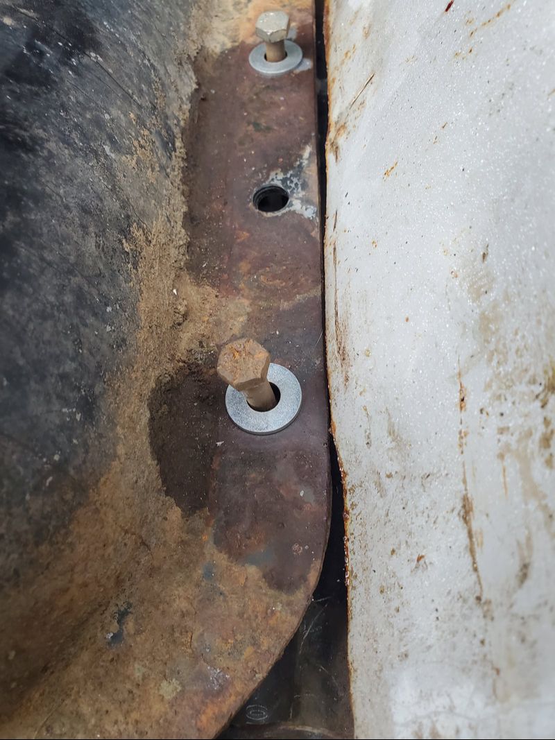 The fuel tank seated on the frame rails after setting up the heater hose. A bolt is already applied through the fuel tank lip, hose and frame rail. With the fuel tank in the orientation it's currently in on Truckstang, the nipples on the pickup were pointed to the rear. I had to remove the pickup unit and test the changing of the orientation to see how I could get the nipples to face forward. I ended up having to carefully twist the pickup screen slightly, in order to allow pickup to sit in the new orientation and not hit the bottom of the fuel tank. In the new orientation, if I left the pickup screen in the same position, it would've hit the bottom of the tank as it curves upward. 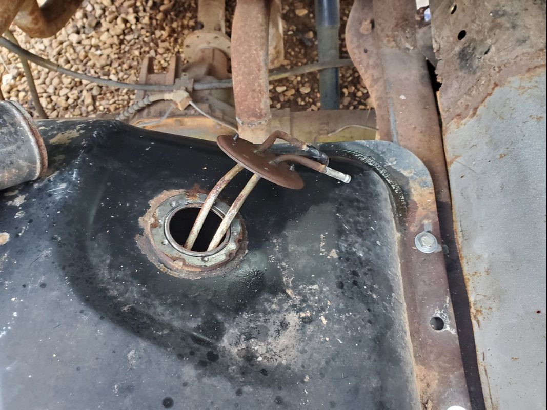 The pickup unit removed to turn the pickup screen to a new position prior to reseating the unit. Twisting the pickup screen allowed me to orient the unit in the direction I needed, but there was another unfortunate issue that I had to accept. The bolt pattern only allowed me to install three out of five of the retaining screws to hold the unit in place. I even tried to widen the holes to see if I could expose the off-center holes to no avail. I installed the three screws, verifying there was no play in the pickup unit. Worst case, I'll have to apply a thin layer of gasket maker to the rubber bushing to further seal the unit if it proves to leak during use. 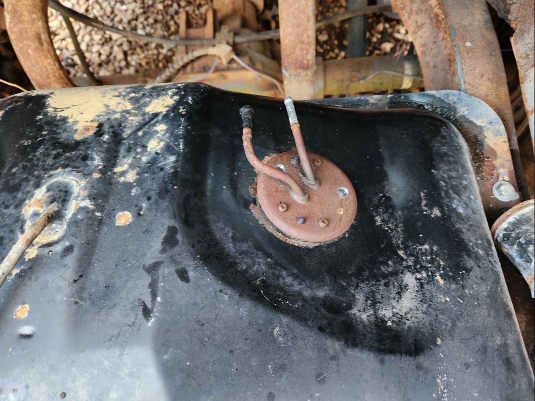 The pickup unit in its new orientation, held in place with three out of five screws. Gasket maker may need to be used to seal the unit. The last part of this part of the fuel system that I had to deal with, still, is the fuel filler tube. Even though I had made some modifications to get the tube as close as possible to the filler neck on the fuel tank, there were still a couple issues I'd be facing. One is the idea that the rubber hose I would need is either the largest radiator hose that I could source, or the actual rubber tube that couples the stock filler tube to the stock fuel tank. The sharp angle that would need to be covered is not achievable with the stock rubber hose. I came to the conclusion that I would have to chop the filler tube down at an angle, and weld an angled piece of exhaust pipe to the remaining filler tube, placing that exhaust pipe at a position where its almost straight in line with the filler neck on the fuel tank. Also, the exhaust pipe is a narrower diameter in order to accommodate normal sized rad hose. 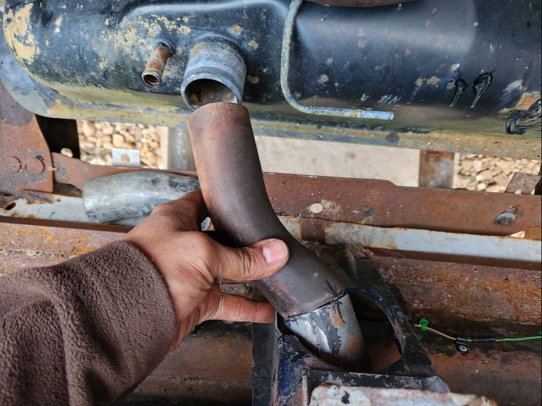 The new filler tube in its test fitting after chopping the original filler tube down and trimming a bit off the piece of exhaust pipe. These two sections will be welded together, leaving the end of the new filler tube facing the filler neck on the fuel tank almost straight in line. After I weld this together I'll more than likely have to hit the junkyard to source a length of rad hose that will fit our application. In the original configuration, the only large diameter rad hose I felt I could find would probably be for some large engine like a diesel bus or industrial truck with a huge cooling system. This way, with the new configuration, I should be able to use a rad hose from a regular full size truck to couple the filler tube ends. After all, this thing is only allowing fuel under no pressure to transition from a filler through to the fuel tank without leaking all over the interior of the trunk. After this is done, I just need to install a short length of fuel line to couple the end of the metal fuel line with the nipple on the pickup unit. Save for the sending unit, I can then move forward to the engine bay and get the carb installed.
At long last, we've finally managed to get the perimeter fence completed, save for the main gate. There was a final section at the southeast corner of the fence line, right by the Dog Kennel Greenhouse, that needed to be filled in. This little section also left an opening at the back of the garden that had proven to be a problem for the ADHD dogs that would have a habit of running out through that opening into the greater yard area. Now, that problem is no more. I had to install one whole 8ft panel and would have to make a 6ft panel from scratch to close in the final gap.
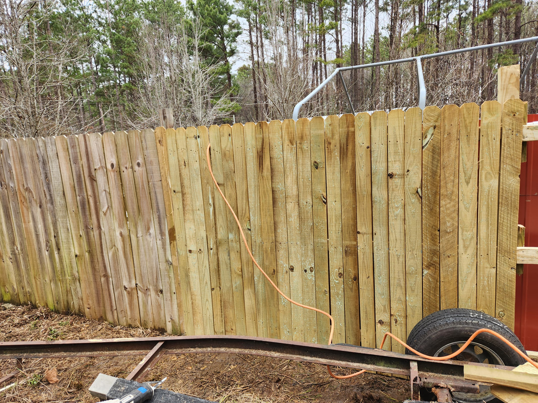
The 8ft panel hung and closing in the opening at the back of the garden. The boat trailer is dead in the way.
Of course it wasn't completely easy to get this panel into position. First of all, the distance to cover between the main driveway and where the panel had to go was mostly sloppy muddy ground. I was able to get the trailer about 1/3 the way in before running out of graveled path and even then almost getting the Tracker stuck. I was able to pull the trailer by hand over another 1/3 the distance before getting bogged down on the soft ground. The final 1/3 was covered by the both of us walking the panel over to the site. Of course we also had to stand the panel upright and maneuver it between the fence line and the boat trailer, which is still unable to be moved due to the broken axle. Once we got the panel in place I was able to get to work. I had to tack up a couple 2x4's to the posts at both ends to be able to provide the surface to anchor the panel to. I would've used deck screws to hold everything up but ran out of them, only being able to use two screws to hold both ends of the panel up, one on either end. I had to use the nail gun to secure the rest of the panel. I also had to use the nail gun for the 2x4's that would make up the 6ft panel for the final section as well. 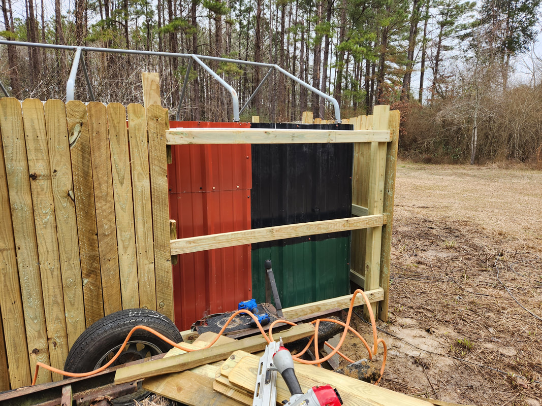
Hanging the three 2x4's that will make up the 6ft panel. At this point the nail guns were the main tool getting these final panels hung.
I used the smaller nail gun to tack up the pickets as well. It was just as well, as it's a waste of small wood screws trying to secure 14 pickets to a panel with three screws per picket. Using a pack of thin nails is way more economical. With the pickets up, all the way to the corner, I used a final picket to overlap the small gap at the corner. With this covered, the perimeter fence is closed in. Save for the main gate, the compound is secured. 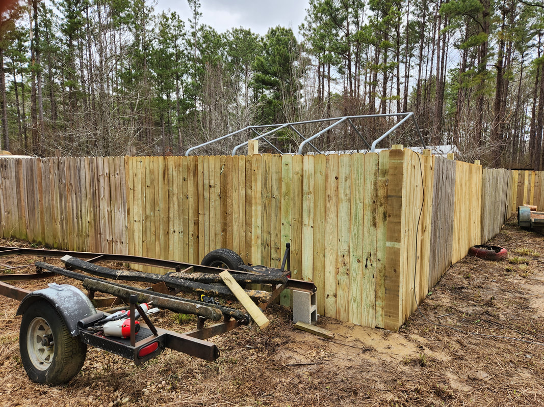
The completed fence line at the southeast corner. Note the corner picket that is overlapping the open corner point.
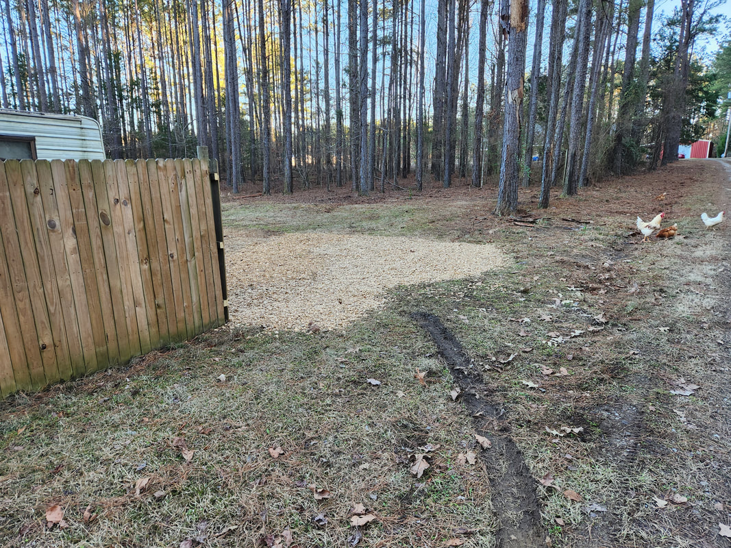
We will start the work on the main gate as I start gathering materials. I will have to get a gate brace kit to use for making the actual sliding gate, then get a gate rail/trolley kit that will have to be anchored to a separate post. The separate post will have to be anchored in the ground along the main fence at a spacing to allow the panel to slide between the post and the main fence. Lastly, I will have to get a motor assembly that will be used for opening and closing the gate, which will roll on trolleys provided in the kit. I will have to build up the grounds around the area where the gate will slide, as well as the main driveway. I'll have to widen the main driveway due to the fact that I will have to narrow the gap of the main gate in order to be able to make a gate that won't end up being too big for any gate opener to handle. Widening the driveway will allow us to make the wide swing necessary to pull in large vehicles like the F250 into the narrower gate. On a lighter note, I did manage to close in the gap for the gravel path along the south fence line, linking to the main driveway, so now I can start making my push towards the east fence line. 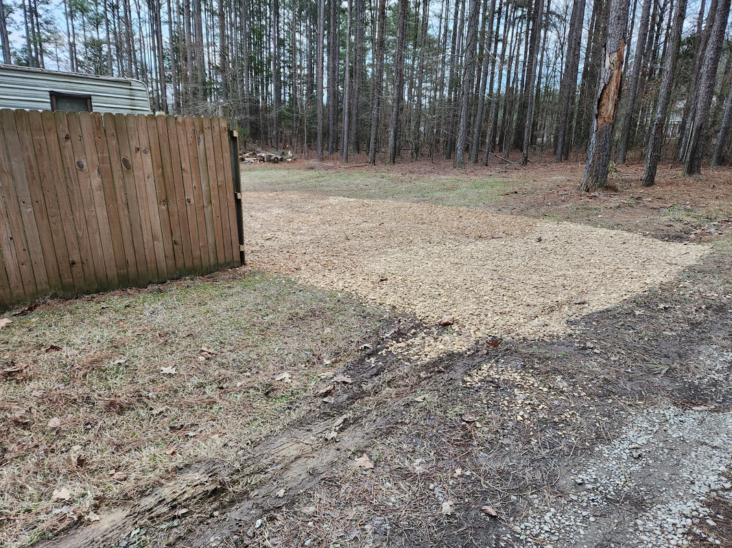
The linking of the gravel path along the south fence line with the main driveway.
Of course the work on the main gate isn't going to begin immediately. Again, I still have to gather materials, but there are other projects I'm trying to close the book on before I take on the gate project. There's a matter of finishing Truckstang, along with the Lawn Mower Carb Conversion on Rustang, and the next real building project, finishing up the Dog Kennel Greenhouse. The greenhouse will be the next focal point for chucking money at, as this project has been at a standstill for almost a year. Stay tuned for some work on that project.
As shown before, the fuel filler tube on the Truckstang would have to be oriented at 90 degrees to the left to coincide with the new filler neck position of the "new" fuel tank. After doing the test fitting, I still had to make some modifications to the filler neck to accommodate the locking gas cap. I had to line up the position of the gas cap at the regular position relative to the new position of the filler tube. I marked the points on the face of the filler tube so I could use the cutting disk on the rotary tool to trim little notches on the face to allow the gas cap the ability to snap into place with the label in the horizontal position. Only thing is one of the points on the face did not have enough of a lip for the cap to latch onto. I ended up having to weld some metal to the point on the face of the filler tube where the latch was not making contact. After welding some slag into place, I ground the excess down to make it flush so the gas cap would sit flush and seal as best as possible. 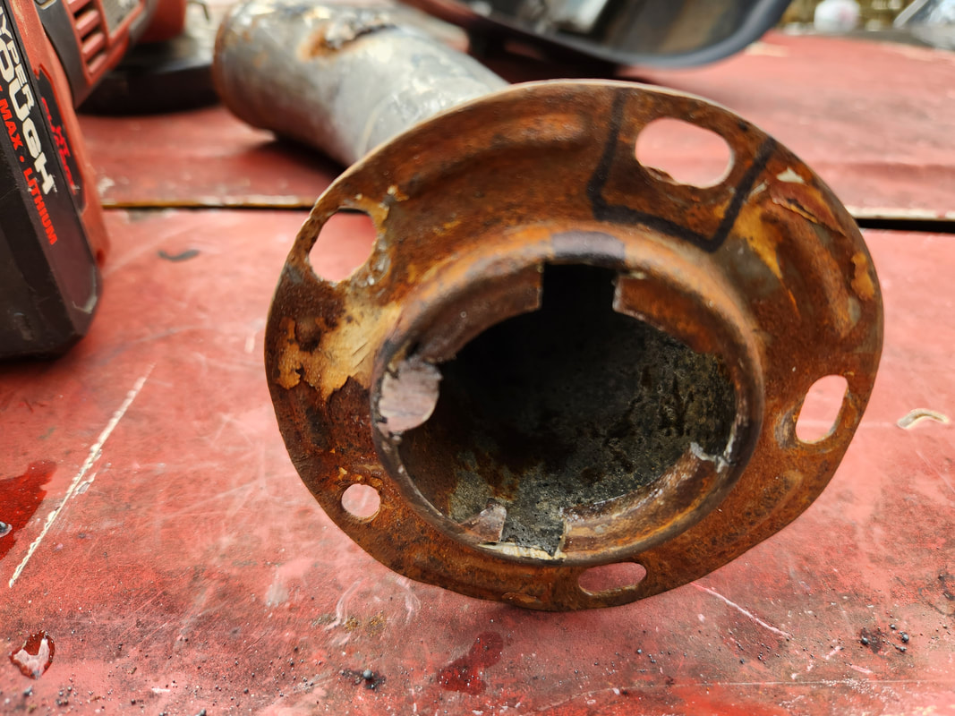 The fuel filler tube with the weld slag on the left side after grinding down flush to fit the fuel cap. With the weld slag ground down flush with the rest of the face surface, I was able to successfully latch the fuel cap down where it sat down with the rubber gasket on the face. I had to make sure the cap wouldn't pop off by moving the cap around to see if the latches were actually holding. After doing this enough times, I was satisfied that the cap would stay in place when the car is bouncing around on the road. With that, I was confident that I could put the filler tube in place permanently. 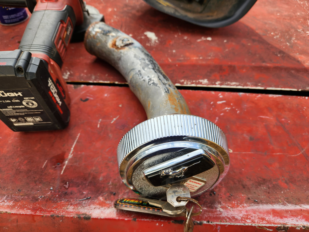 Fuel cap snapped in on the filler tube successfully. Instead of using the three bolts I used to hold the filler tube in place, I dug out enough nuts and bolts to fill all the holes to ensure that the filler tube mounting holes were filled. With the filler tube in place, I moved the piece to make sure it was nice and sturdy so again, the gas cap won't be prone to pop off, as well as not pop the rubber hose off when the car's in motion. Simple little thing, but with that, I can write off this part of the fuel system. 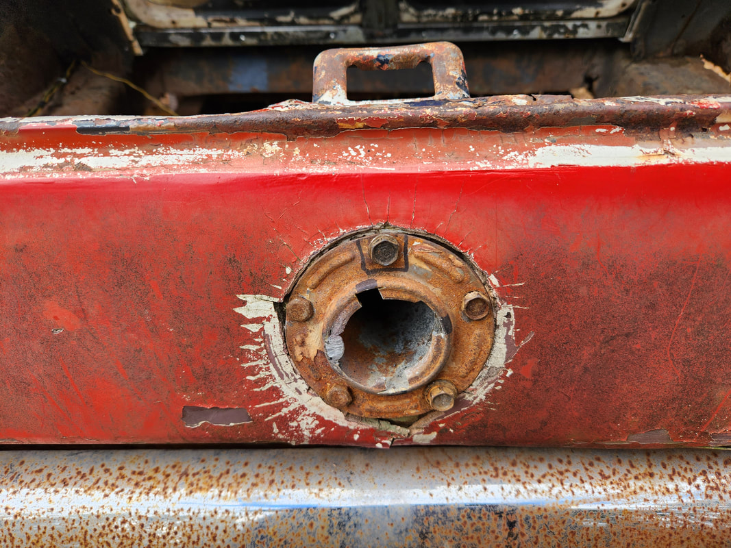 Filler tube is completely bolted in this time. 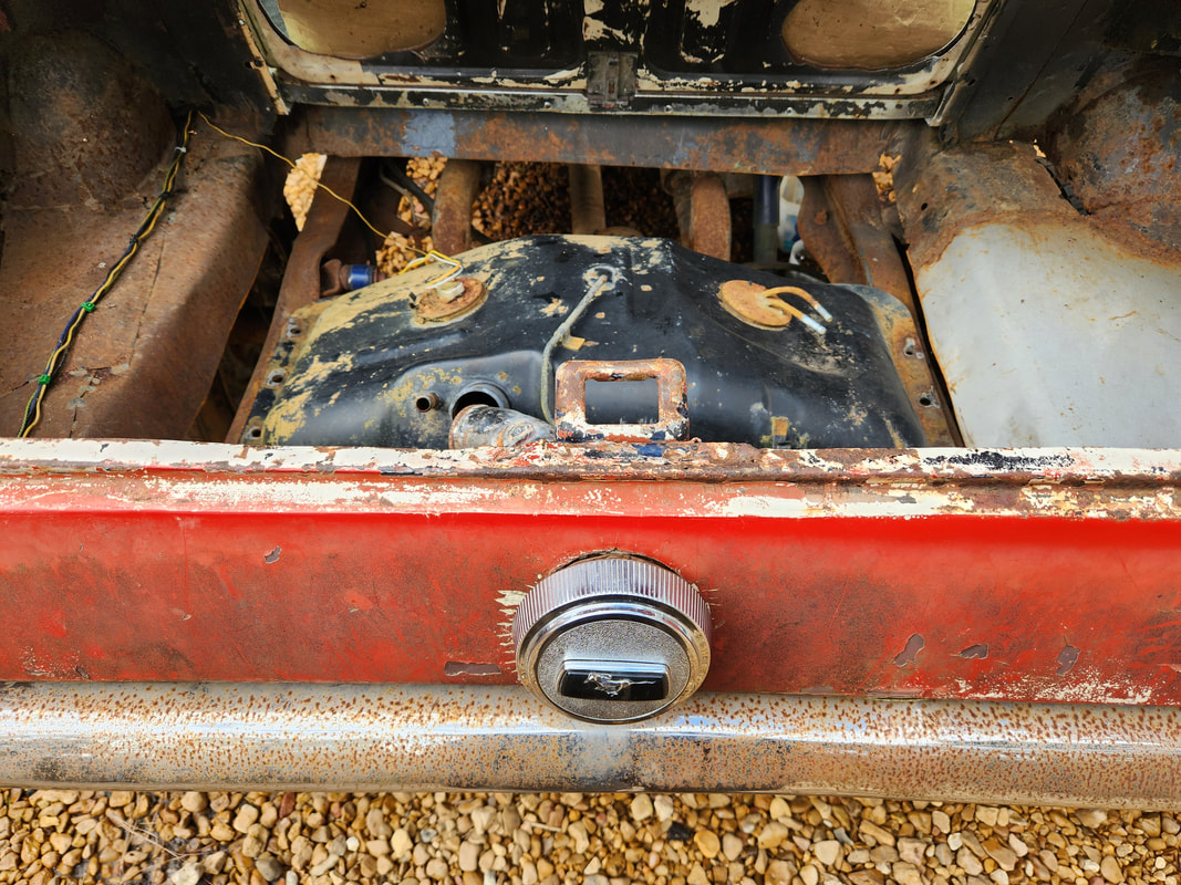 Gas cap is snapped in place with the label in the right position despite the filler tube being turned 90 degrees to the left. Success! With this simple little part of Truckstang addressed, i can now move on to getting the fuel tank installed in its entirety as well as try to complete the closing in of the trunk floor so I can finish up what amounts to the body/structural work on the car. This will also keep chickens and other critters from invading the interior as the speaker panel in the rear of the car has cardboard blocking the empty speaker holes. I still have to weld on some sheet metal to those holes to cover them up and try to make that panel flush and closed up as well, even though on another note I could fully remove the panel. If I did that, I would have to completely close in the trunk all around, as the trunk would be an extension of the rear interior, much like a Corvette is set up, sort of like a reverse trunk, even though on this car the trunk would still be accessible from the rear. We'll see, but either way, things are coming together more and more. Sometimes it just takes standing back from a problem to suddenly come up with a solution to said problem. In this case the problem is what to do about a fuel tank on the Truckstang. The original fuel tank is unable to fit into the trunk opening due to the Ranger frame rails and exhaust pipes, so the latest solution was to acquire a boat fuel tank to use for the alternative fuel tank. After a while of not doing anything, I suddenly came up with an idea. I checked out the old Chevy LUV fuel tank that I still had on hand. Ironically, this fuel tank was almost perfect for the application in Truckstang. I did some preliminary sizing up and aside from a minor roadblock that can be overcome, this fuel tank would be perfect. 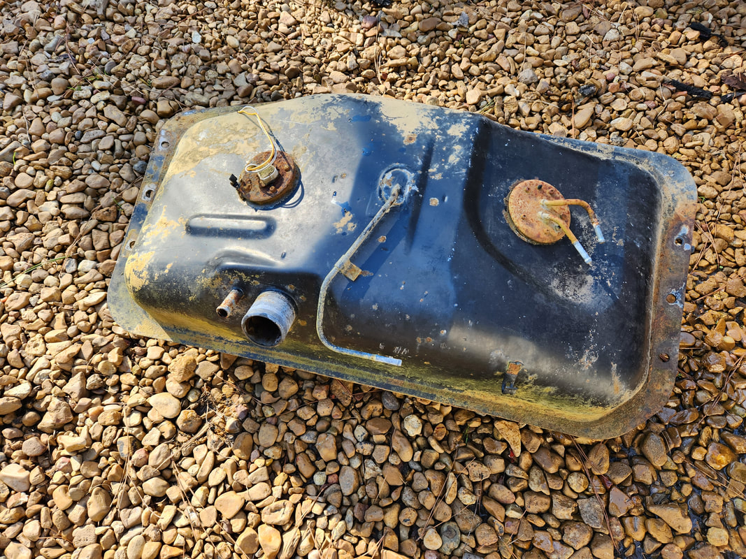 The old Chevy LUV fuel tank, which I managed to stubbornly hang on to for a long time, well there's a good divine reason for this apparently... On the section of truck frame rails where the fuel tank would sit, there are small wings in the metal going around what appeared to be a couple bolt holes. These little wings made the spacing between the rails just shy of the width of the fuel tank. The angle grinder took care of these little wings, trimming off the 1/2" of metal and making the rails perfectly straight going front to back. With that, the fuel tank was able to sit right in the opening between the two frame rails. 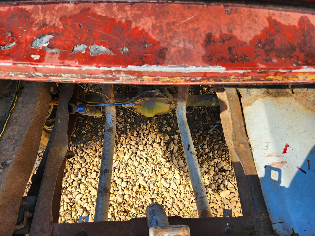 The trunk opening showing the truck frame rails, about midway in the pic the tops of the rails curve out slightly to the inside, creating little wings that need to be trimmed straight. 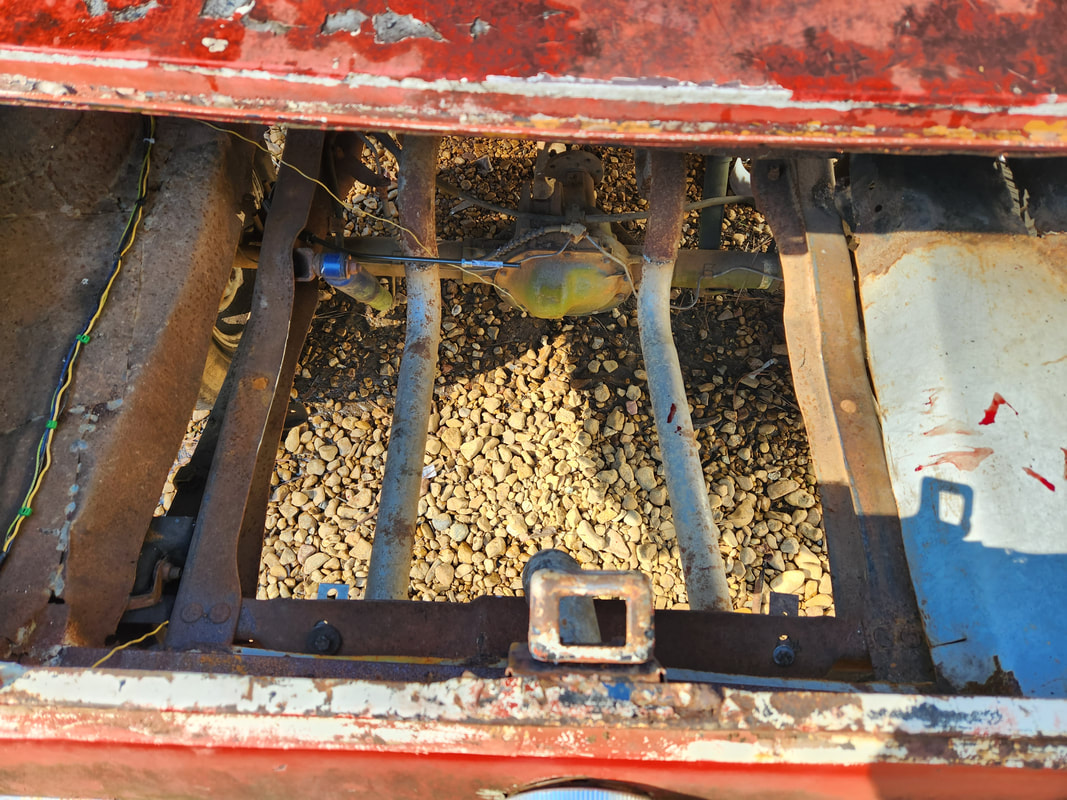 After using the angle grinder, the frame rails are nice and straight, able to accommodate the LUV fuel tank. With the fuel tank set in the space between the frame rails, the next thing that I addressed was how to couple the filler tube with the filler tube end on the fuel tank. The tube end on the tank is off center to the left of center, so I would have to somehow situate the filler tube to where it can come as close as possible to the LUV tank's filler tube end. I ended up having to trim some metal from the rear panel support frame, which also holds the loop for the trunk lid, to accommodate the filler tube being set at a left angle. I removed the bolts and turned the filler tube 90 degrees so the tube would be angling horizontally to the left instead of down and center. 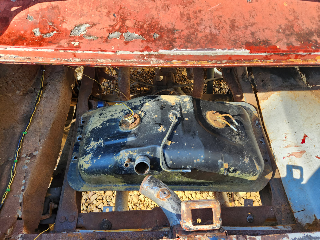 The LUV tank setting on the frame rails almost perfectly. Note the filler tube in its initial test fitting in a new position to allow it to come close to the LUV tank filler tube end. Upon the initial fitting of the tube in this position I found that the tube was hitting the side of the support frame/bracket, so I had to trim some metal from the left side and bend it out a little bit to give the spacing necessary to allow the filler tube to sit flush on the taillight panel. After doing this little trimming, the tube sat flush and came close enough to the LUV tank filler tube end that I would only need a few inches of rubber hose to couple the filler tube ends. 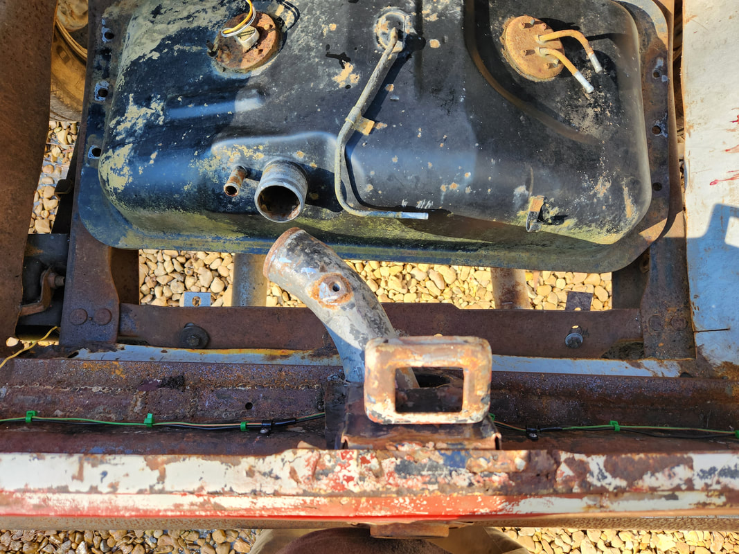 Closeup of the filler tube in its new orientation to meet with the LUV tank filler tube end. 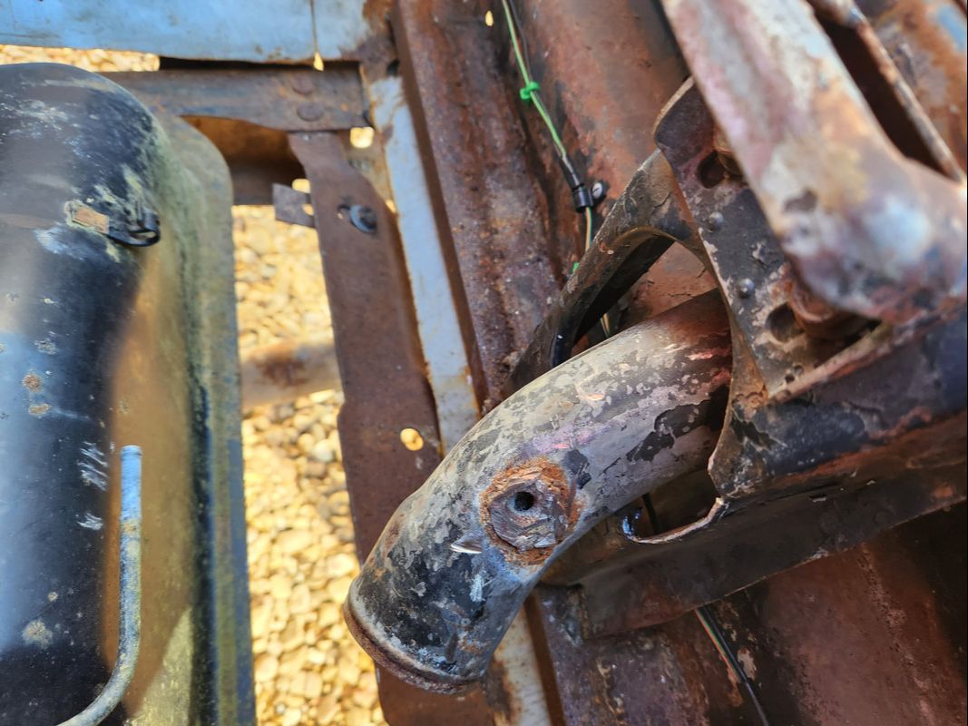 Angle showing how the support frame/bracket is trimmed to accommodate the filler tube in its new position. The next thing I wanted to address is how to set up the rest of the trunk floor. After I do secure the fuel tank to the frame rails, I will want to add some sheet metal to complete the trunk floor to close things in so I can actually use the trunk in some capacity. The easiest way I determined to do this will be to weld in some tubing in front and behind the fuel tank to serve as support points for small sections of sheet metal that will be welded in place to close in the trunk floor around the fuel tank. I will then cut one last piece of sheet metal to lay on top of the fuel tank to fully cover the unit and close in the fuel tank. I don't have all the specifics down, but that is the basic concept that will be used to close in the trunk. I will have to take into account the filler tube of course, but other than that, this idea should accomplish the goal of closing in the trunk. 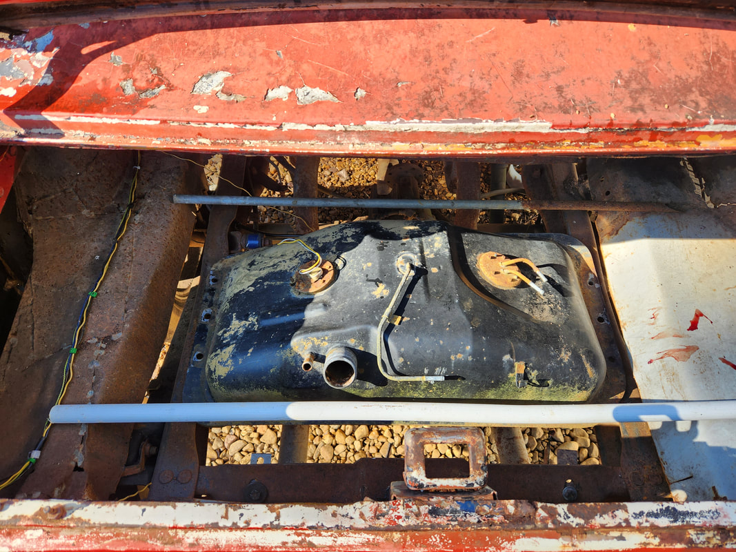 Metal tubes test fitted in front and behind the fuel tank to show how and where sheet metal would go to build up the trunk floor. The next minor thing I wanted to address is the fuel cap. Because the filler tube will be set 90 degrees off, the fuel cap will also be 90 degrees off. To fix this, I will have to trim notches on the filler tube that will allow the cap to snap in place and be level with the filler tube in the new orientation. Once all this is done and the fuel lines are hooked up, I can finally write off the fuel system as done. Save for the carb, which I also need to bolt down, this work will conclude another critical component of the Truckstang.
Over 20 years ago I managed to get my hands on what was at the time one of the new for the time budget air rifles, the Crosman 1077. This air rifle is a CO2 powered semi auto air rifle that somewhat models a Ruger 10/22 or similar semi auto .22 rifle. This gun claims to shoot at 625 fps, which for a CO2 semi auto gun was rather impressive. At the time I was in love with this gun because of its performance potential. Of course now there are air guns out there that would put this gun in the same class as a Daisy Red Ryder. With the world of large bore air rifles, large bore semi and even full auto air rifles, this gun is far from being a performance shooter. Needless to say, this 20+ year old veteran deserved to be resurrected.
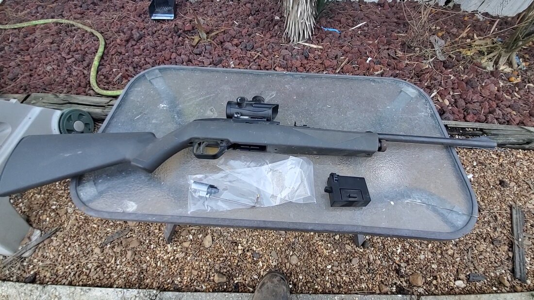
The Crosman 1077 with a Crosman red dot optic added.
With an aftermarket valve kit in hand, I was ready to get this gun back online. The kit comes with a new power valve and gasket for the CO2 base valve or whatever that part is called. I had to break the gun down, removing the action from the stock and pulling the receiver apart into the two pieces to be able to remove the power valve and CO2 base/valve. 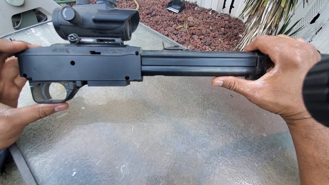
The receiver/barreled action after removing from the stock. Only three screws hold the action to the stock.
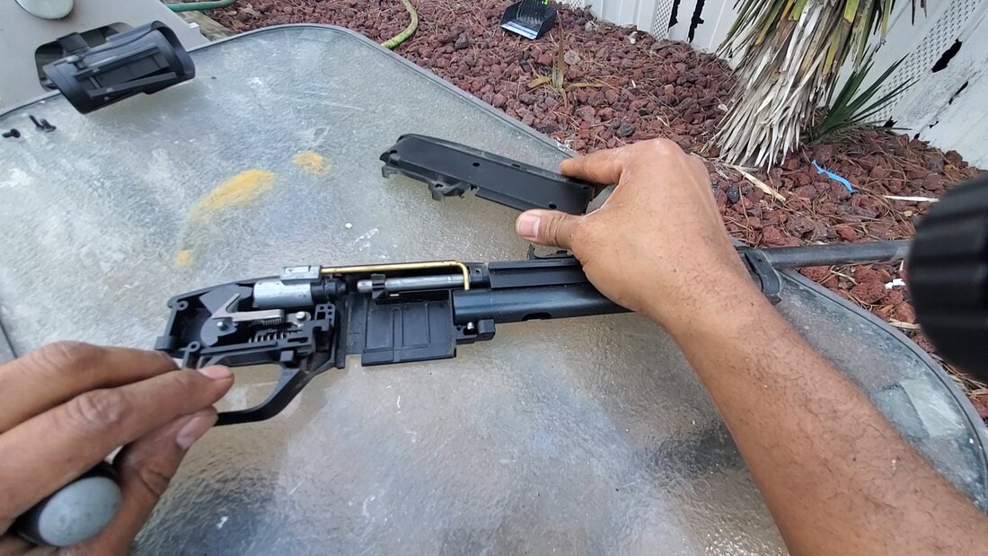
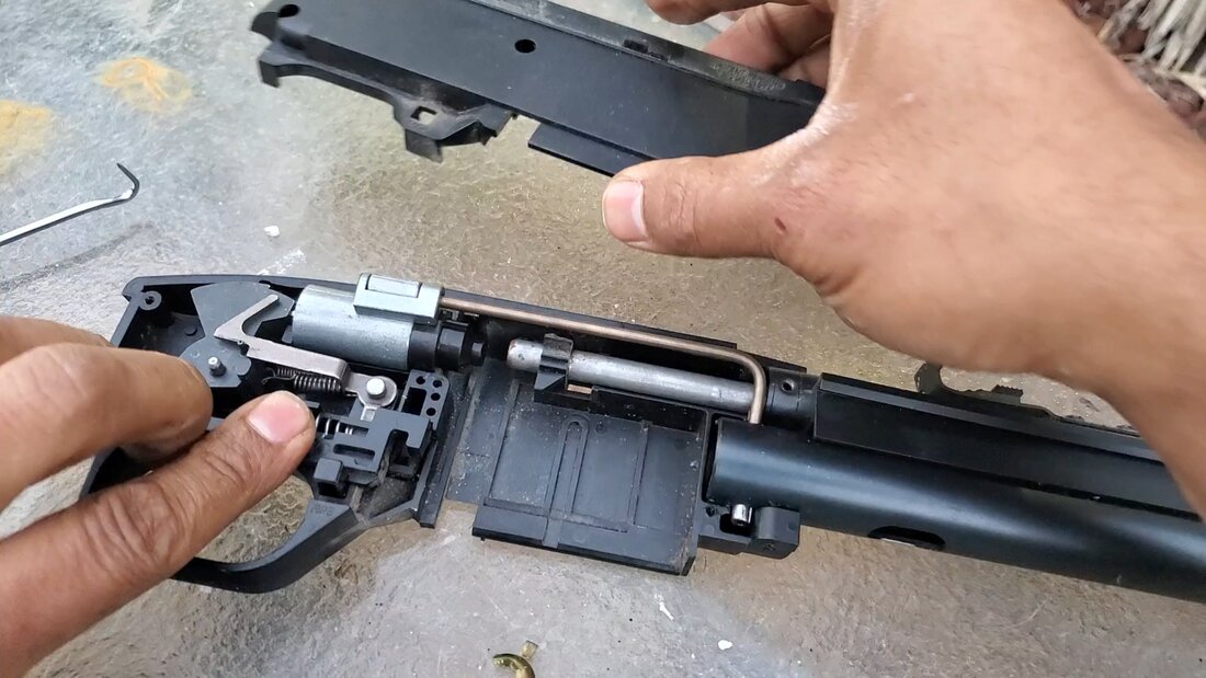
Exposing the internals of the receiver after removing the cover. The trigger group and power valve will have to come out.
The first thing I repaired was the CO2 valve. To do this I unscrewed a retaining ring and scraped out the remains of the plastic/wax seal that surrounds the CO2 piercing nipple. I replaced the seal and reassembled the unit, then placed the piece back in the CO2 cartridge tube. The CO2 valve used a roll pin to secure the unit in the tube. Once this was done, I was able to reassemble the rest of the internals. 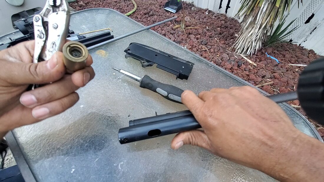
The CO2 valve with the dry rotted seal that needs replacing.
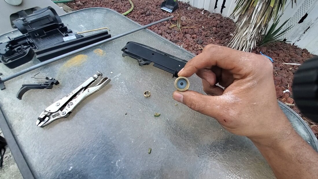
The CO2 valve with the new seal in place, ready for the retaining ring to be installed.
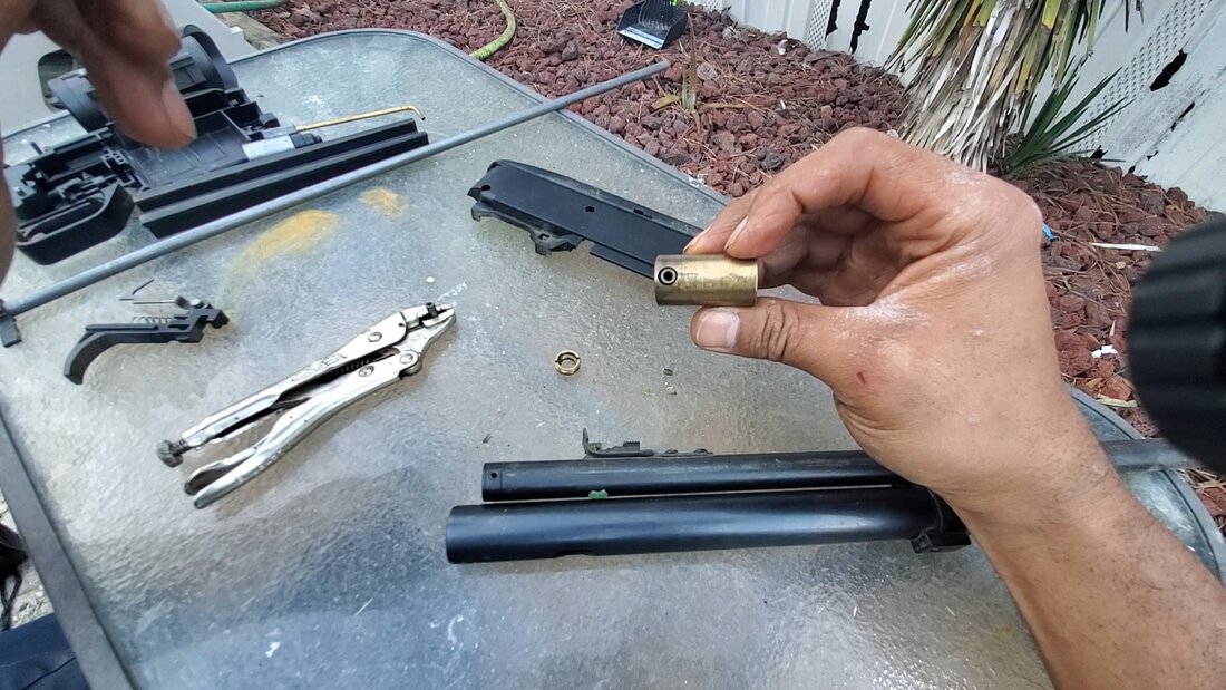
The CO2 valve with the gas tube bushing in place.
Inserting the CO2 valve into the CO2 tube. Note the bushing that has to be installed before the piece is installed. The bushing holds the gas tube that delivers gas to the power valve.
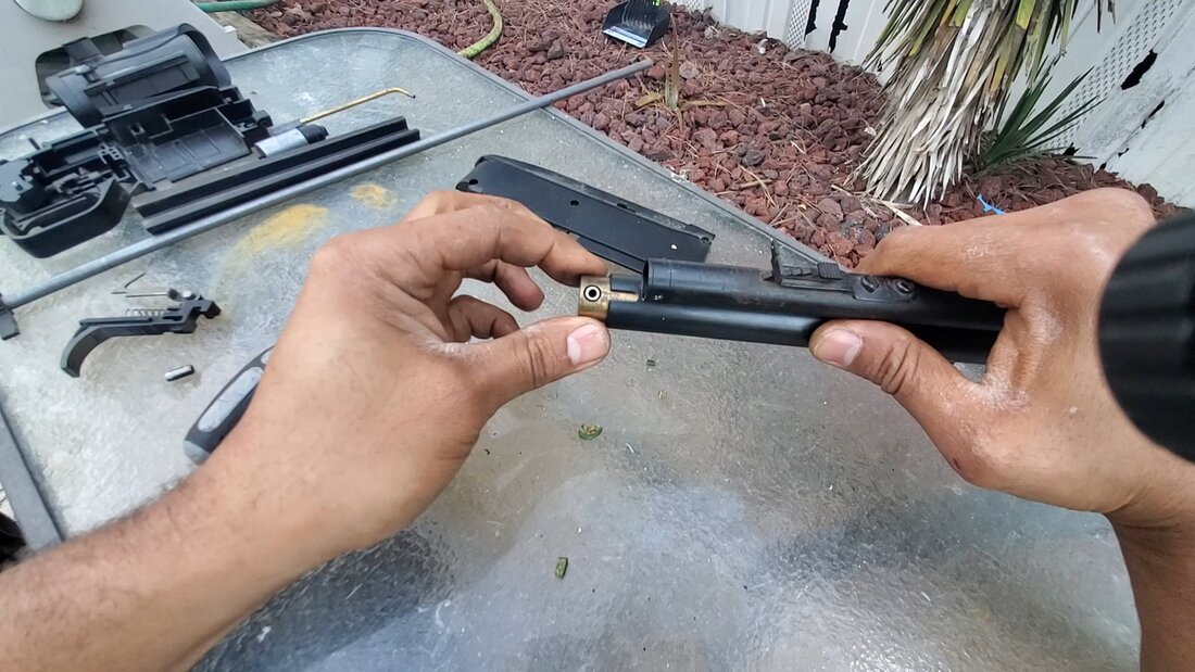
The power valve was seated with the gas tube into the CO2 valve and the trigger group installed back in place. After reassembling the barrel and receiver cap, I was able to put the whole works back into the stock to get the gun reassembled. 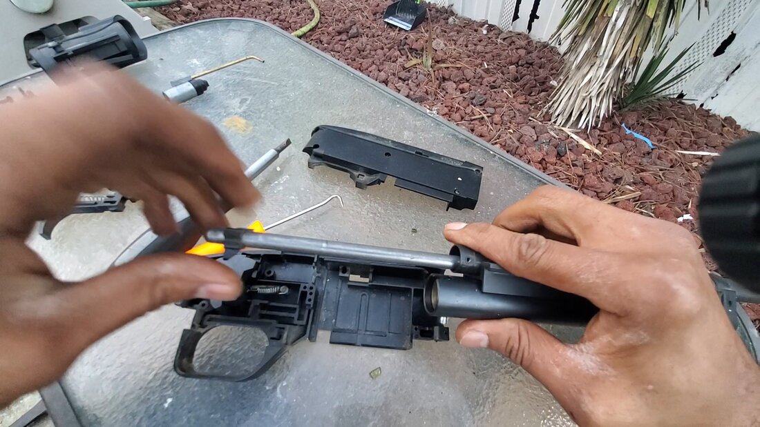
Installing the barrel before putting the power valve back in.
Replacing the receiver cover after replacing the power valve and trigger group.
With the gun back together, I'll have to test this thing to confirm all is good. I just received a chronograph which will play a pivotal role in future gun tests, so I'll be using this tool to test the performance of this air rifle after replacing the valve components. I did save the old power valve, which for all intents was still good, just the CO2 valve seal was bad. With that, I plan on doing some experiments with modifying the power valve in order to squeeze some more power from the gun. From what I've seen in similar modifications, the power valve was disassembled, and the spring inside switched with a lighter spring so the valve would be opened more when the hammer strikes home. Of course, adding a stronger hammer spring will help in opening the valve more just as well. If I can manage to make these changes, maybe I can turn this regular backyard plinking gun to something capable of taking small game.
As usual when we do routine yard work around the compound, we can't go on without doing some more gravel. Even though we've pretty much closed in the compound and everything within those walls is graveled up, the work on spreading the gravel is not done. On the outside of the fences, I plan on laying gravel along those fences to serve as a pathway to get to the east side of the compound, where the trailers are stored. I already started laying gravel along the south fence line to connect to patches of gravel that was already laid into this area. The patch that was extending out from the pathway between the Storage Trailer and garden is where I'm laying more gravel, reaching out to the main driveway. Once this link is done, I'll then add gravel on the opposite side, going east, to connect to another large patch of gravel that I had laid for use in setting the tow dolly and boats earlier.
The gravel path further laid to close the gap towards the main driveway.
With the gravel laid, I moved on to the north east corner of the compound, over where the shooting range is located. I had to clean up some fallen branches along the north fence line, adding to my growing burn pile but the main thing was to clear the area around the back of the Shooting Range as well as along the tree line, going east from the Shooting Range. There was a mixture of fallen trees, weed trees, blackberry briars and poison ivy. As before, I had to pull out all the big guns to work this shitshow. 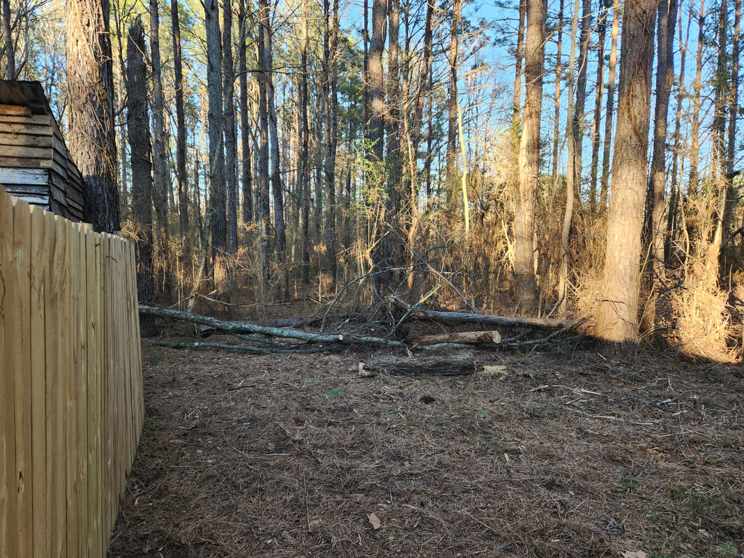
Looking along east fence line to the north, showing the amount of area cleared. The fallen tree in the background will eventually be cut up later to further clear the area.
I had to work my way slowly but surely through the floral crap, chopping stuff and cutting the stuff into manageable pieces to stack on to the burn pile. I'm trying a new routine of being able to cut the detritus into smaller pieces so the stuff can be stacked better and tighter, allowing me to build a smaller burn pile while still stacking the maximum amount of trash into said burn pile. 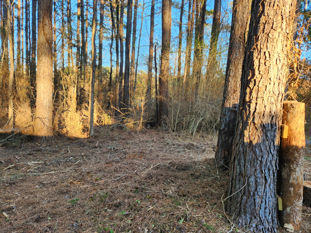
Looking east from the east fence line with the Shooting Range to the immediate right, showing the cleared area.
I managed to clear a large area behind the Shooting Range as well as around the northeast corner of the fence line. I even managed to drop the remains of a couple dead trees that were in the area. After analyzing the area, I determined that by clearing the area that I did, I can actually set the area up to allow me to actually convey small vehicles along the north fence line and around the rear of the Shooting Range then between two trees just east of the Shooting Range. Once I get everything finalized with this area, we will be able to move vehicles all the way around the compound on either side. 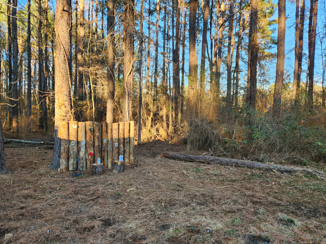
The Shooting Range and surrounding area showing how much brush was cleared, note the fallen tree that has to be cut up.
Even as I finished clearing up the area, I fired the burn pile to get things started so I could get a good ember pile started in order to allow me to continue to throw more plant scraps onto the burning pile. I started to cut up the larger fallen tree trunks and move those cuts onto the already burning pile so they can get heated up just as well. I even managed to chop some stumps flush with the ground just to get ahead of the game on that end. Once I exhausted the batteries in my tools, I stopped cutting and adding garbage to the burn pile. 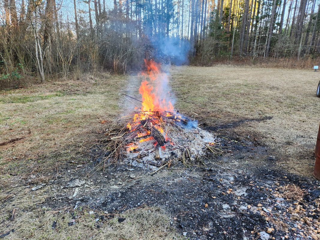
Contributing to greenhouse gas emissions...
There's still plenty of trash to cut up and start a new burn pile once again, so I'll be starting a new burn pile once this one cools down. As with the south fence line, I'll run a gravel path from the main driveway along this fence line and around the back area behind the Shooting Range and out into the clearing to provide another path for travel. Of course, this means I'll be working with the spreading of gravel for quite some time until all these areas get fully covered. At the same time this work will allow us to clear the surrounding woods enough so to make the area more pleasant to look at while being able to move through the woods. I've had plans on cutting some paths through the woods to create some go kart/ATV paths that we can use for testing such classes of vehicles. Doing this type of work is a head start to eventually establishing paths through the surrounding woods, so expect to see more instances of burn piles being formed and more gravel being laid as we do manage to get the woods trimmed up through the future.
With everything ready to go on the lawn mower carb setup for the Rustang's 6 cyl engine, it was go-time. The gasket I cut out was glued down with gasket maker and another layer applied on the outside before applying the intake assembly. Because the base wasn't the thicker base of the stock 1bbl carburetor, I had to use a large nut as a spacer between the top of the base plate and the bracket that holds the throttle cable in order to allow the longer bolt to tighten down on everything. At first I had the assembly positioned where the soup can was facing the front, which would've allowed me to be able to pull the air cleaner element easily, but after looking at everything, the problems created by this arrangement far overshadowed the convenience of being able to easily access the air cleaner element in its current design. I ended up switching the assembly around where the air cleaner can is facing the firewall. 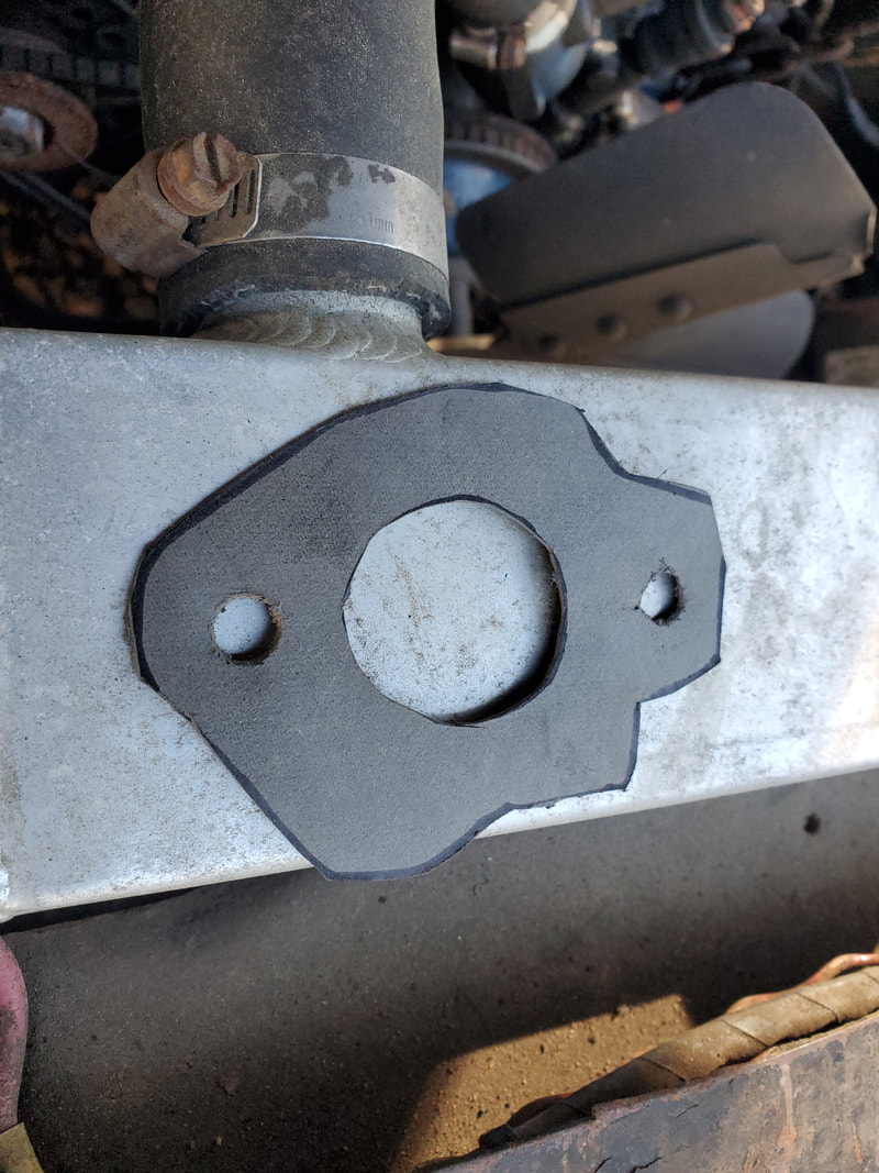 The gasket for the intake plenum base cut from gasket paper stock. 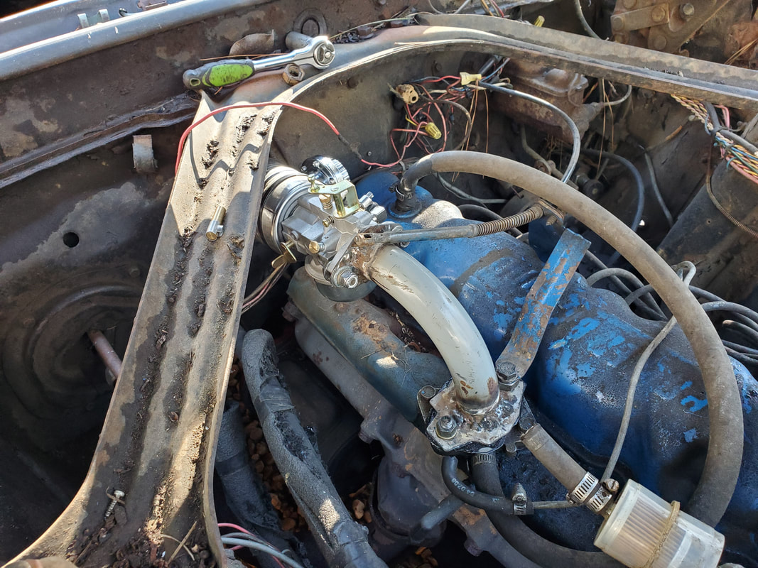 The lawn mower carb and intake plenum bolted down in the new position with the soup can air cleaner facing the firewall. What this means is I'll have to pull the carb off to replace the element if it proves too hard to remove the element material from the can through the few inches gap that is present between the can and firewall. Placing the intake/carb in this position allowed me to be able to get the throttle cable in position where its movement would coincide with the movement of the linkage on the carb to operate like normal. It also placed the fuel pressure regulator in a position to easily hook up to the end of the fuel filter with just an extra length of rubber hose, about 2x the length of the original piece that coupled the filter to the 1bbl carburetor. 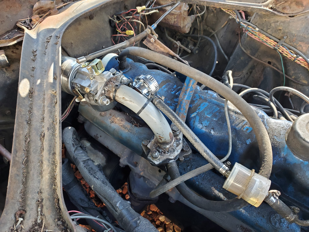 A shot of the piece of rubber hose that connects the fuel filter to the nipple on the pressure regulator to complete the hookup of the assembly to the car's old fuel system. To secure the throttle cable, I added a piece of angle iron to the bracket that originally held the throttle cable. After removing the cable from said bracket, I took the angle iron and drilled some holes to allow me to bolt the piece to the bracket at an angle, then bolt the throttle cable to the other end of the angle iron piece. This placed the throttle cable in a position to line up with the linkage on the lawn mower carb. The throttle linkage had a snap piece on the ball tip that I was able to remove and place on the Mustang throttle cable end to allow me to snap the cable to the lawn mower carb linkage with ease. Once this was done, I was ready to test start the engine. 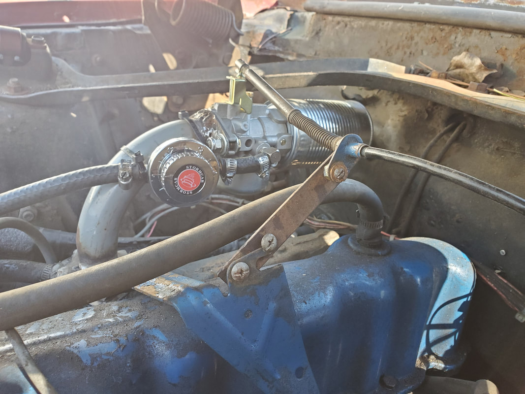 Closeup of the angle iron piece bolted to the throttle cable bracket to help support the throttle cable where it can easily hook up to the lawn mower carb's throttle linkage. To make things a little easier, I used a remote starter switch so I could manually operate the linkages on the carburetor. I still hadn't hooked up the choke so I had to be able to work that piece, as well as the idle and A/F mix screws. Plus being under the hood allows me to be able to monitor the operation of the engine up close to make note of any issues. I cranked the engine over and because I already had fuel in the filter, the engine didn't take long before the pump pushed fuel to the carburetor, allowing the engine to start. 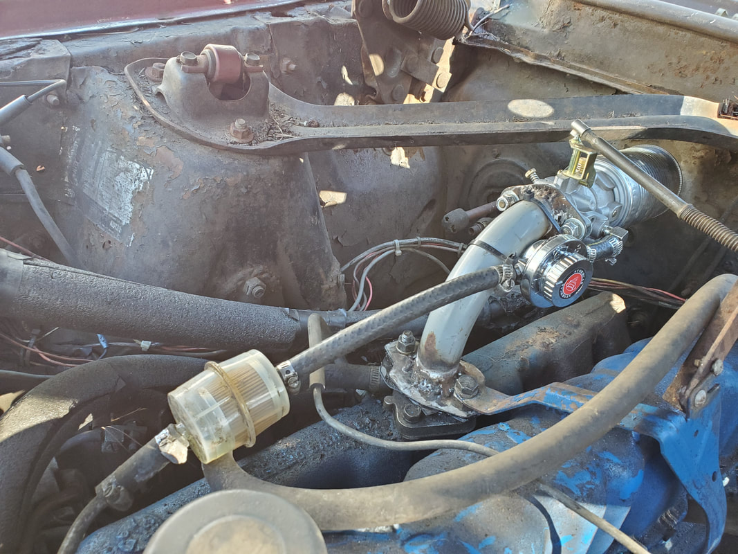 Another angle to the lawn mower carb assembly with intake plenum, pressure regulator, fuel filter/hose, and throttle cable hookup. I had to make some immediate tweaks to keep the engine running but I ended up finding that the engine in the beginning was happy at about 3/4 open choke. All the way and the engine was acting like it may have been starving of fuel. At first the carburetor flooded out, causing overflow fuel to leak out and into the soup can air filter. After a while, things seemed to balance out, probably the float valve finally seated itself and the leakage stopped. The engine appeared to take the throttle pretty good when the choke was at 3/4 open. I'm not sure if the carburetor was throwing too much gas out but I did notice some gas moisture around the base of the intake, like maybe too much was leaking out still, I may have to investigate that further. The engine ran pretty good but I'm sure I'll have to dial in the ignition and also get some vacuum to the tube feeding the distributor so I can have vacuum advance. When I tapped off the nipple on the intake plenum on the cylinder head, I did get a better throttle response on the count of the vac advance working. I might also have to tap another nipple with which to use to have a controlled air leak to help balance out the A/F mixture so the engine can run smoother. A threaded bung for an O2 sensor and A/F meter will better allow me to monitor this particular reading to better tune the engine. What all this means is this project will be more of a long term project that will be an enlightenment to this concept of running an engine. Even though others have tried this, my first hand experience with this will give me the knowledge necessary to better apply this whole ideal on future projects. |
