|
For a while now we've been trying to float two different sites, really three sites, The Improvisation Center, The Improvisation Center Insider (this one), and Preparedness And Politics. While TIC documents the individual projects we work on here in whole, TIC Insider documents the every day or every other day occurrences on the homestead regarding any of these projects and other things that we have going on here. P&P was an attempt at documenting our exploits in survivalism and preparedness as they would be known in the old and new circles, with a little political twist not leaning on any given side.
Well, it's a little overwhelming to be trying to float all three sites when most of the energy is expended on TIC and TIC Insider. Because of this, it only made sense for me to merge P&P with TIC. Another reason for this is because of the idea that some of the projects featured in P&P were also featured in TIC. Part of survivalism and preparedness involves some improvisation, especially when it comes to situations where supplies or resources may not be available. Even the whole premise of improvising to build different things around the homestead weigh in with preparedness. With that, I'll be pulling the plug on P&P, instead posting any survivalist/preparedness posts here and of course featuring any larger projects on TIC. I will leave P&P up for the older posts in so those still interested can view those posts. I'll post an update on P&P noting the end of the line on that site and the merging to this site. So stay tuned for blog posts on guns and other projectile tools, improvised survival tools and techniques, even life hacks that are survival focused and can apply to everyday living to better prepare you for moving forward into the future with a focus on being able to be more self reliant and prepared for whatever the future may stick in front of you.
0 Comments
After installing the remote oil filter assembly, I needed to source some fresh hose for the nipples on the two pieces. I also had to get that final brake line I needed for the brake system. This meant a trip to the junkyard. While at the junkyard, after I got the brake line, I thought I'd kill two birds with one stone and grab a driveshaft from another short bed single cab Ranger, since the rear end on the Ranger frame has a specific plate on the input shaft of the rear end. At the same time, there may be a remote possibility that the slip yoke on the Ranger shaft may very well fit the older C4 on the Truckstang's 289. With those parts, and a good roll of 1/2" hose for the oil filter, and while I was at it, a fuse box, I was able to get to work.
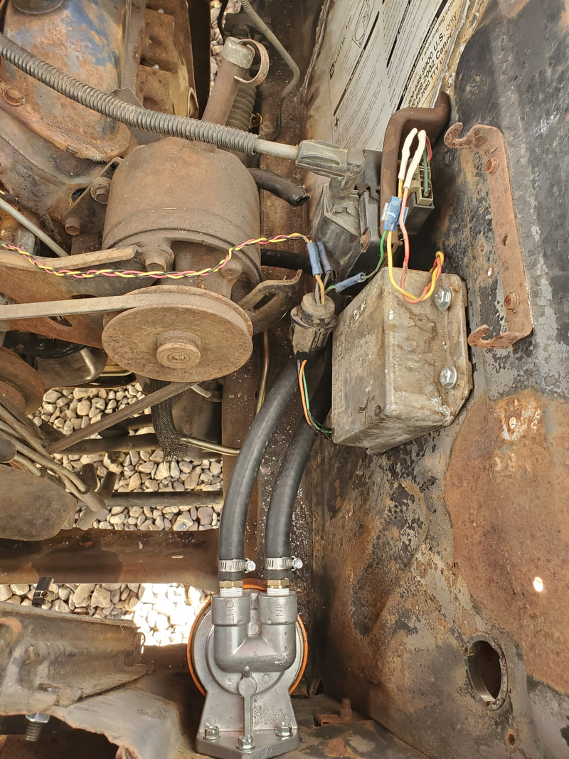
Remote oil filter base with 1/2" hoses attached to nipples leading down to other base.

Engine block base with hoses attached to nipples. Hoses are routed under the PS pump and are away from any component that can compromise the hoses.

Brake master cylinder with other brake line attached to complete the brake system. Master cylinder cap is off after filling reservoir with oil for initial test.
With that little order of business done, I put some brake oil in the reservoir and pumped the pedal some in order to try and move some oil through the system. Afterward, I broke open the bleeders on the front calipers to let the oil gravity feed down to and out of the calipers. I tried to do the same with the rears but no oil made its way to the back. I'll have to do a textbook bleed with my shop buddy pumping the pedal while I open the bleeders to check and see if pressure is even being made by the master cylinder. Worst case I'll have to return this unit and get another one from another junker truck and hope that one plays out. Next order of business was the beginning of the rewiring of the car. This involved mounting the fuse box under the dash around the same area the old unit was located. As an aside, I did take a moment to remove the outside air vent duct that was essentially in the way anyway. It was rusted frozen so it was really not a viable piece to keep under the dash. I would end up having to cap off the port later but until then, removing this piece cleared the underside of the dash that much more so work will be easier under there. First place I started was with the cigarette lighter socket. This was a simple hookup, just one wire. This would be going to a single fuse that won't be hooked up with the rest of the circuitry as this particular circuit will have a constant 12v feed, same as the interior lights and brake lights. 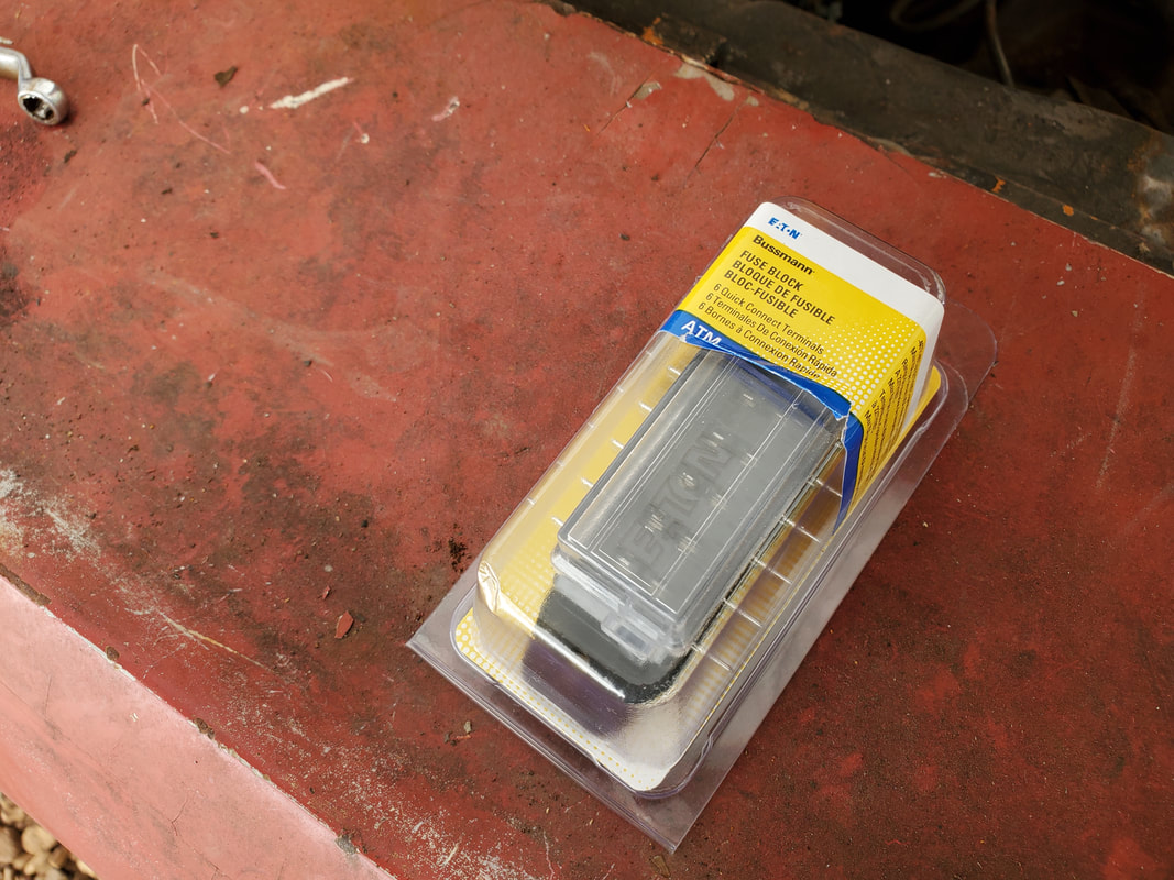
New fuse box that will be the basis of the Truckstang's new electrical system.
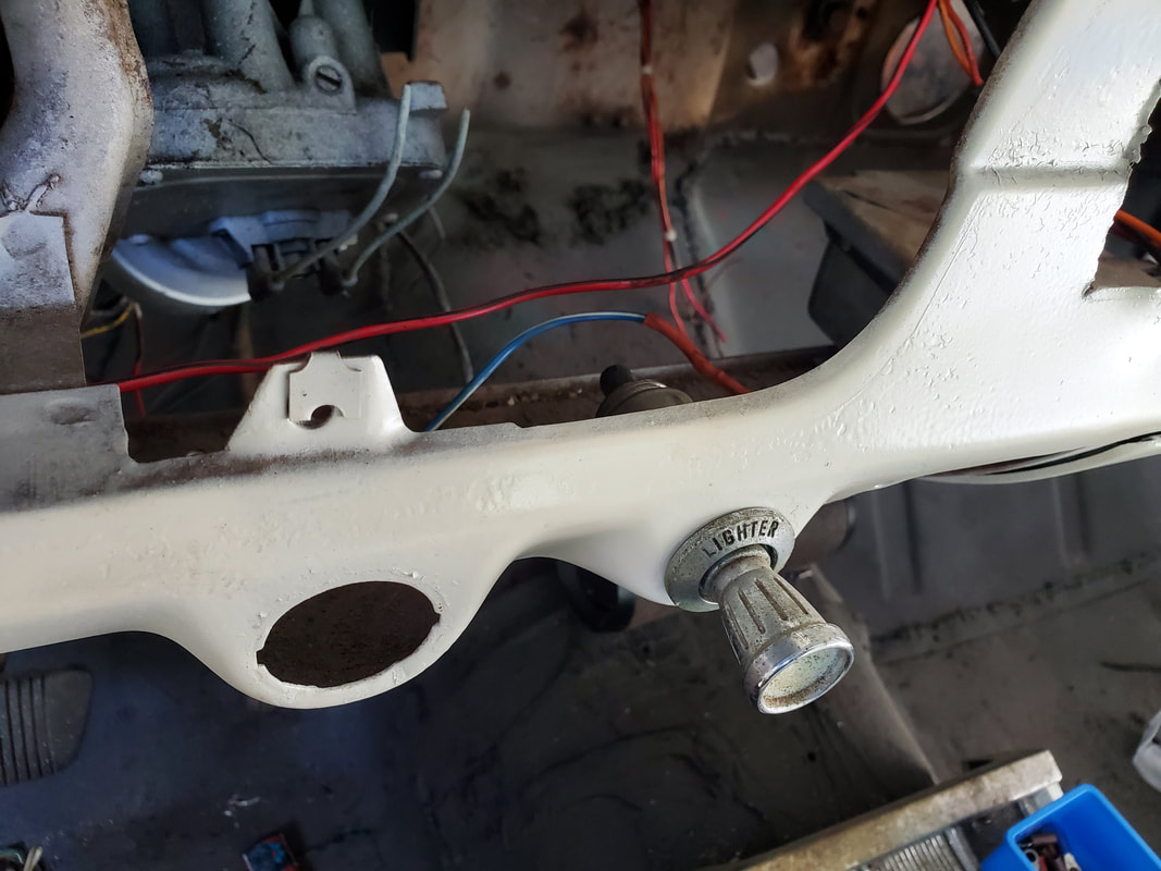
Cigarette lighter socket mounted and wired up.
With the cigarette lighter hooked up, the next thing I did was the wiper motor switch and motor. I had to get a diagram from the interwebs to give me a layout of the wires so I'll know where to route the wires. With that info in hand I was able to wire up the switch to the motor, leaving a lead that will need to be hooked up later. That lead is for the washer motor. I had to hook up a lead for ground and the power feed line. That line went to another point on the fuse panel. Right after this I hooked up the lines for the HVAC blower motor switch. This only consisted of a few wires. One is a power line and the other two would've went to the two speed resistor on the old motor. All I could do here was wire up the power line, coming from the fuse box, using a two way connector to allow me to hook up both the wiper and the blower motor switch to the same fuse. This line went to the switch and the other two lines went over to the point where I'll end up mounting a new HVAC box. Later on I'll also have to add an aftermarket AC system, which will have me adding another connection for that blower motor and the compressor clutch. 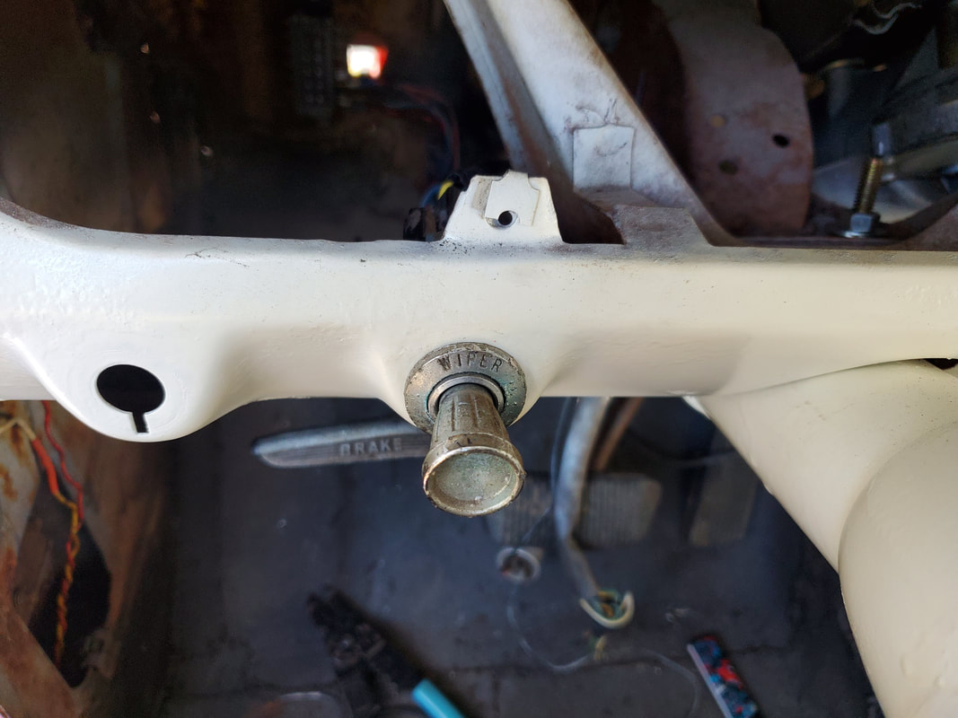
Wiper motor switch mounted and wired up.
Wires for HVAC blower motor routed and tied up to keep things nice and neat. These wires are routed over to the general area that I expect to mount the new HVAC boxes.
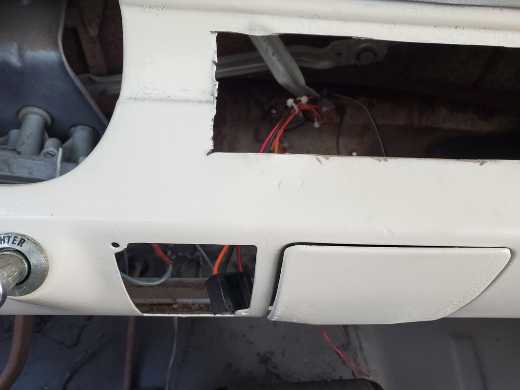
Plug for blower motor switch hanging in the area where the HVAC panel goes. I'll have to mount an extra switch for use with an AC compressor later on when I do add an AC system.
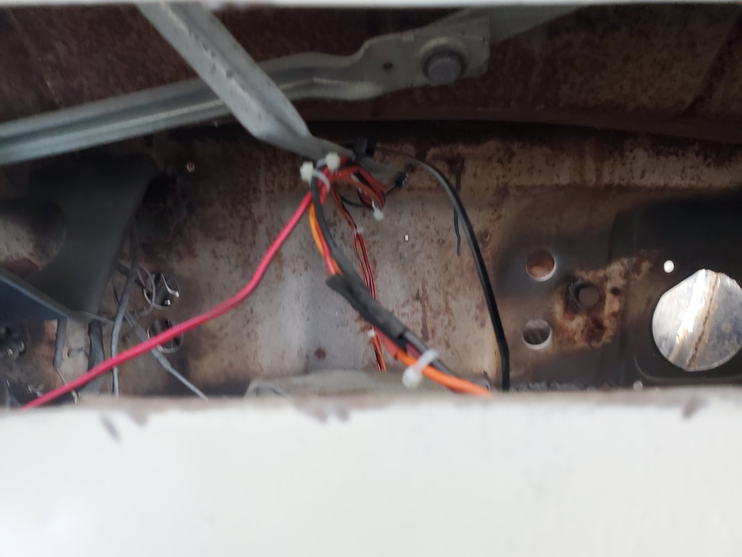
The last thing I did for this session was wire up the two interior lights that are mounted in the side panels I trimmed to mount in the rear seat area. These panels already have the lights wired up with a good length of wire so it only made sense for me to target these next. I ended up having to pull off the door jamb trim panels and the front side panels under the dash to allow me to route the extra wire that I spliced to the ends of the existing wire. The wires were routed in the channels up to the front and up through the sides of the body to under the dash where the door switches are located. The door switches are of the grounded type, where instead of switching 12v they're switching the ground from the load. I cut a wire from each pair to splice to the door switch, while routing the other wire over to the fuse box. Of course the passenger side switch had to have extra wire spliced in to route the circuit across the dash over to the driver's side and down to the fuse box. 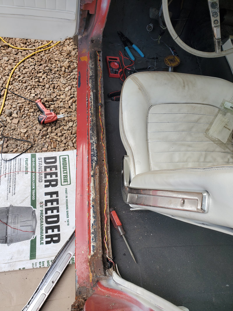
Pair of wires from the left interior light routed through the door jamb channel to the front to be connected to the fuse panel.
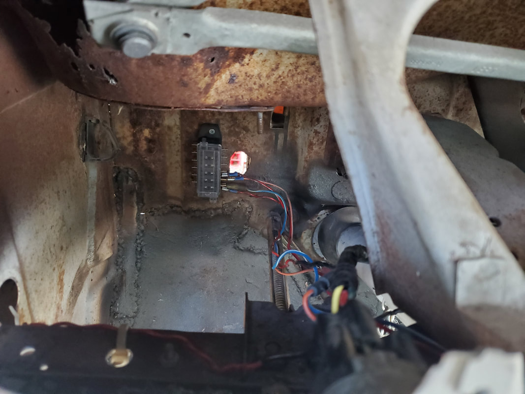
The fuse panel mounted on the driver's side firewall with several circuits already hooked up.
With the interior lights done, my next plan of attack is the rear. I have to wire up the taillights, brake lights and turn signal lights. The taillights and brake lights are simple in the sense that both sides are spliced together. The turn signals will each have their separate lines routed forward. I'll probably end up running lines for the backup lights and license plate lights as well. The license plate light would be spliced in with the taillights and the backups would have to have a separate line routed forward to be connected with the fuse panel and the shifter switch. As with every rewiring job, its tedious but easy in the end.
The next order of business on the Truckstang is the installation of multiple components pertaining to the engine all the way up to and including the exhaust system. A couple of smaller components for the engine would not be able to be hooked up but will at least be able to be secured in place prior to actual rewiring. Other components like the radiator and the ignition system are able to be installed in place completely but too, will not be able to be fully hooked up. As for the exhaust system, I'll have to size things up and more than likely have to cut and reweld things to make the whole system fit. I also ended up switching over from the old Mustang GT headers to a set of old stock manifolds with a length of pipe hooked up to them via flanges, removed from the 73 Mustang.
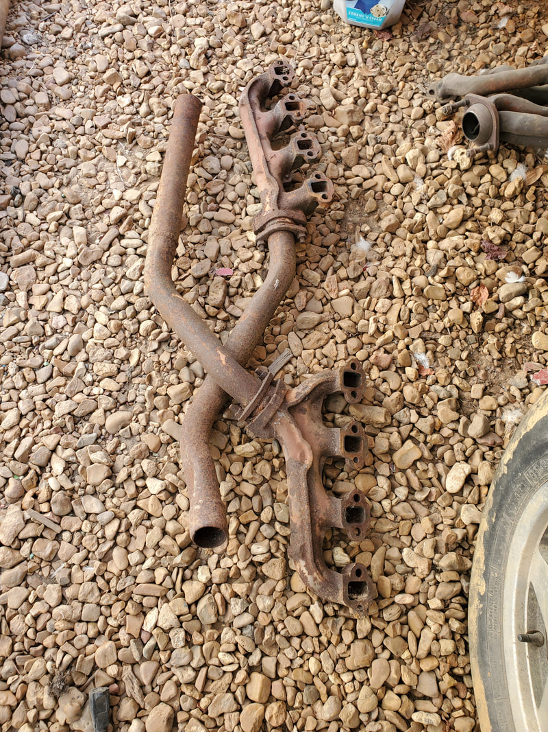
Stock 73 Mustang exhaust manifolds with flange pipes and length of exhaust pipe attached.
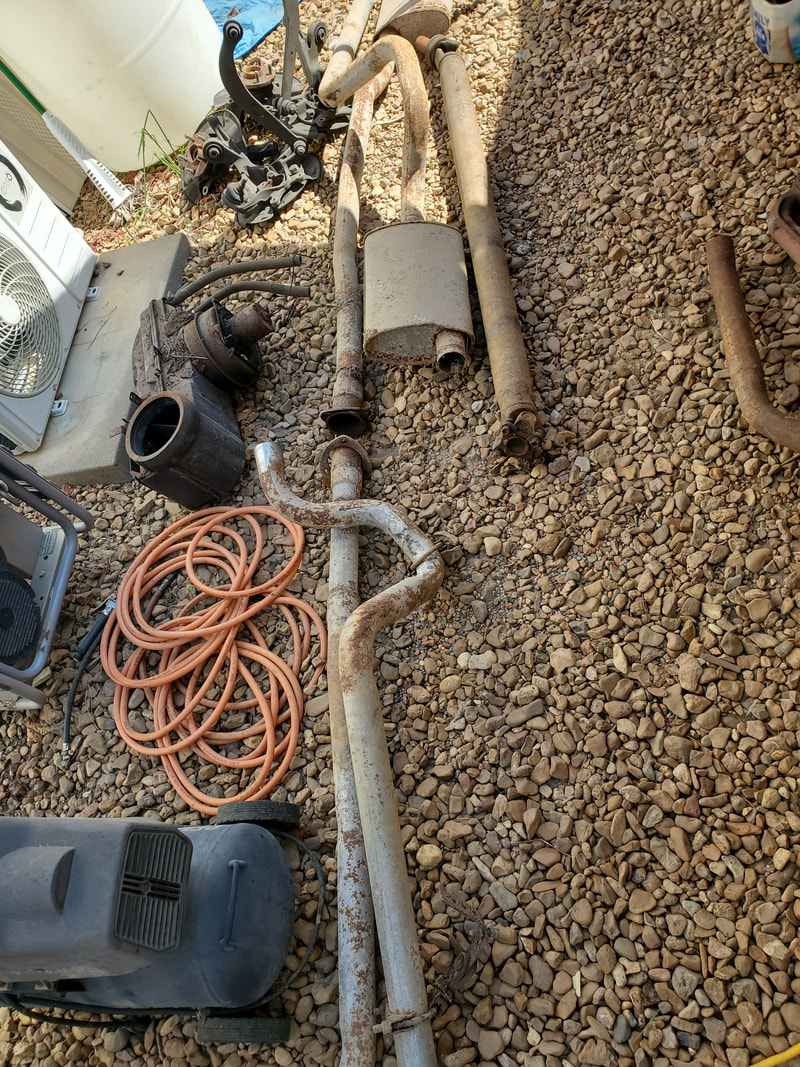
The old exhaust system that was pulled from the Truckstang in the beginning.
I started off with a couple small components, the voltage regulator and starter solenoid. These were simple installations, requiring just drilling a couple holes in the firewall to accommodate 1/4" bolts which with nuts, held the two components in place. I was even able to attach the cable from the starter to the starter end of the solenoid. I'll still have to hook up a battery cable as well as get the wiring diagram for the voltage regulator in order to hook up the alternator properly during the rewiring process. 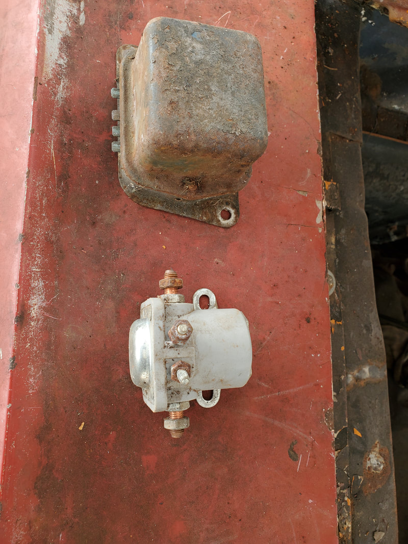
The voltage regulator and starter solenoid, both of which were removed from the car during the initial teardown process.
With the voltage regulator and starter solenoid in place, I moved on to dropping in the Duraspark ignition system. I already had a complete system pulled from the same 289 V8 that's currently in the car, again, when I initially stripped down the car. This system consists of the distributor, the wiring hooking the distributor to the ignition module, spark plug wires and a high voltage newer style ignition coil pulled from a newer Windsor V8 car from the 90's. All I had to do was remove the retaining plug over the hole on the top of the engine block and drop the dizzy in place, locking it down. I'll set the timing based on where the rotor points when I find TDC. I had to drill some holes to bolt the ignition coil and ignition module to the left fender panel. With that I hooked up the wires from the dizzy to the two electrical components. 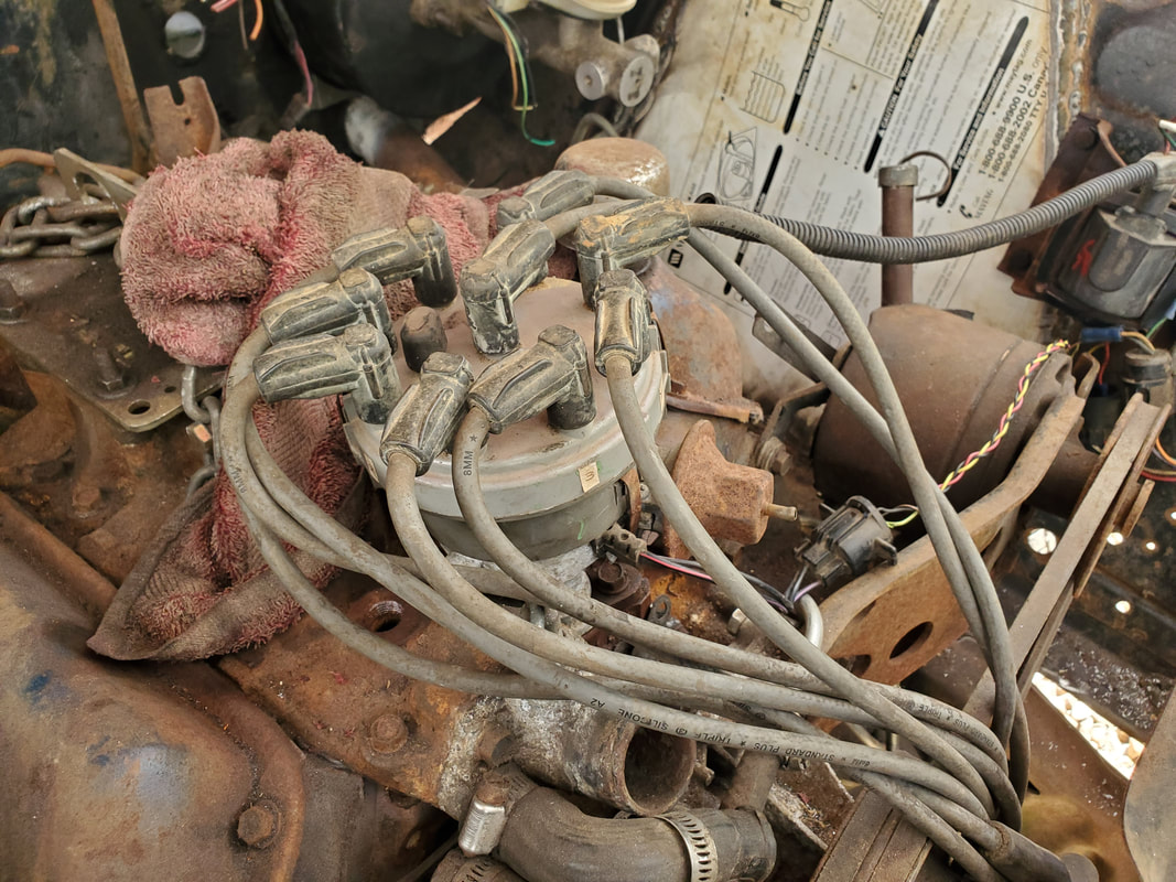
The Duraspark distributor with wires still hooked up to it from when it was removed from the car initially.
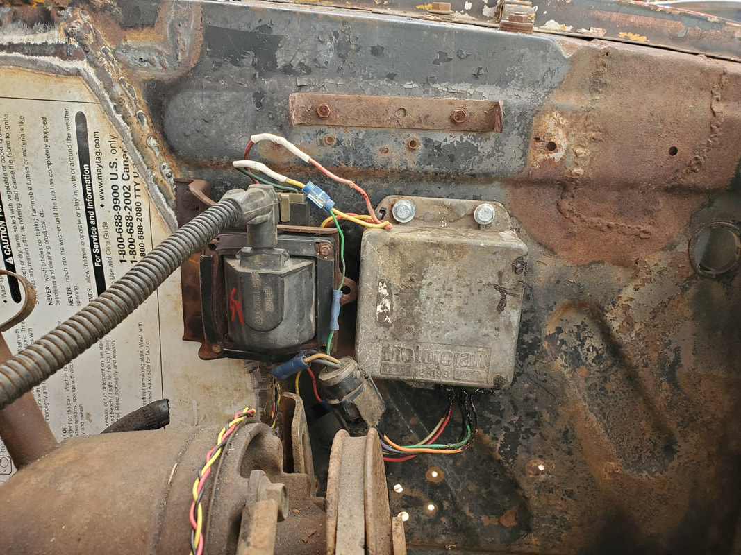
The ignition coil and module bolted up to the left fender wall. Note the wires hooked up to the components.
With the Duraspark system in place, I moved on to the radiator. Since this was the radiator that was in the car originally, the bolt holes on the core support would line up just fine. Four nuts and bolts later, the radiator was in place. I was even able to hook up the lower radiator hose and one of the transmission oil lines as they were still in place on the engine and transmission, respectively. I might have the other hose and tube around here somewhere, which if I do, I'll at least be able to get the cooling system completed. 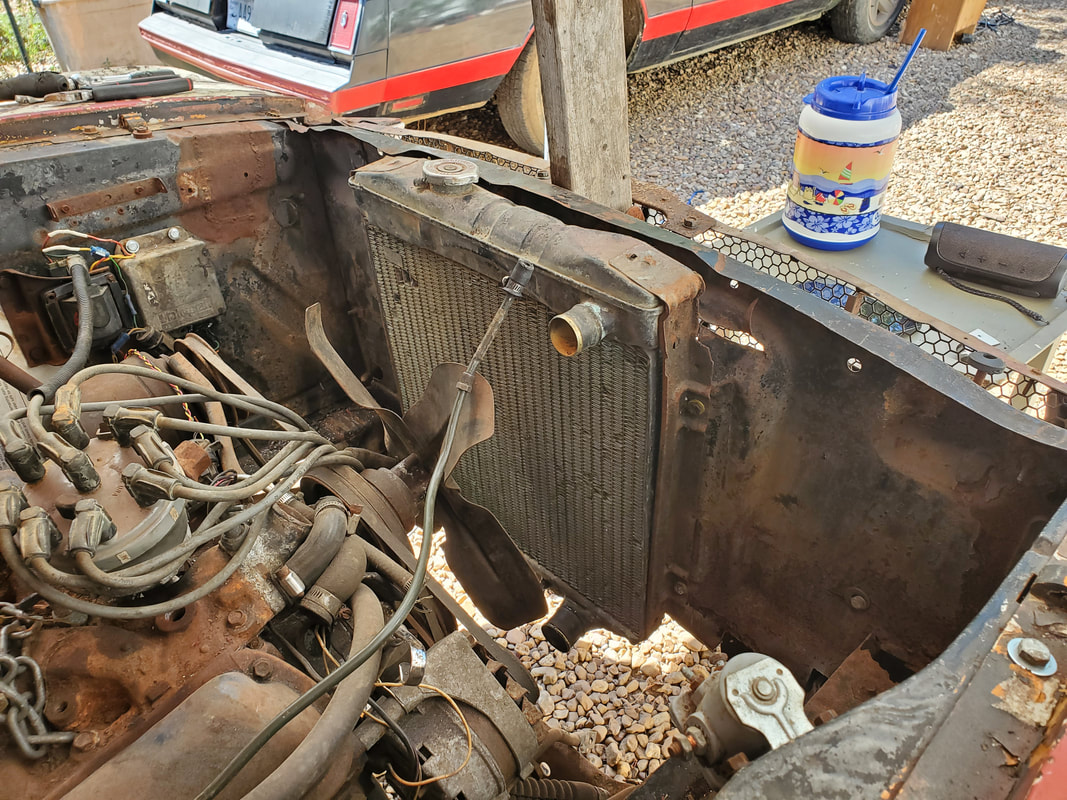
Radiator installed on the core support, hopefully this old thing doesn't have any pinholes that will become a problem later...
With all these components in place, the next thing to install, and by far the largest part, is the exhaust system. But not right now, we'll get to that in the next installment. Stay tuned.
With the steering completed for all intents, the next move is getting the brake hardware installed. This consists of a brake booster and master cylinder sourced from the junkyard, along with a brake line that I needed to replace. Of course since this hardware came from a Ranger, installation on the Mustang firewall would not be straightforward. After removing the old master cylinder, which was useless by any means, I had to map out where the holes would have to go to accommodate the studs on the brake booster. Luckily there was a plastic cover piece that went over the back of the booster that had the bolt holes on it. This was for the sake of protecting the back in case of leakage, oil won't just spurt out every time the pedal is depressed. I used this plastic piece to map out the holes on the firewall. 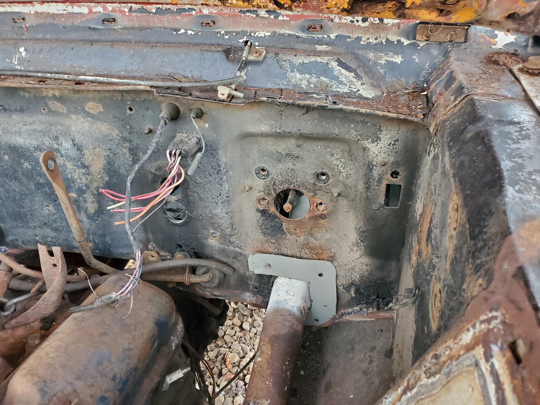 Spot on firewall vacated by the old master cylinder. 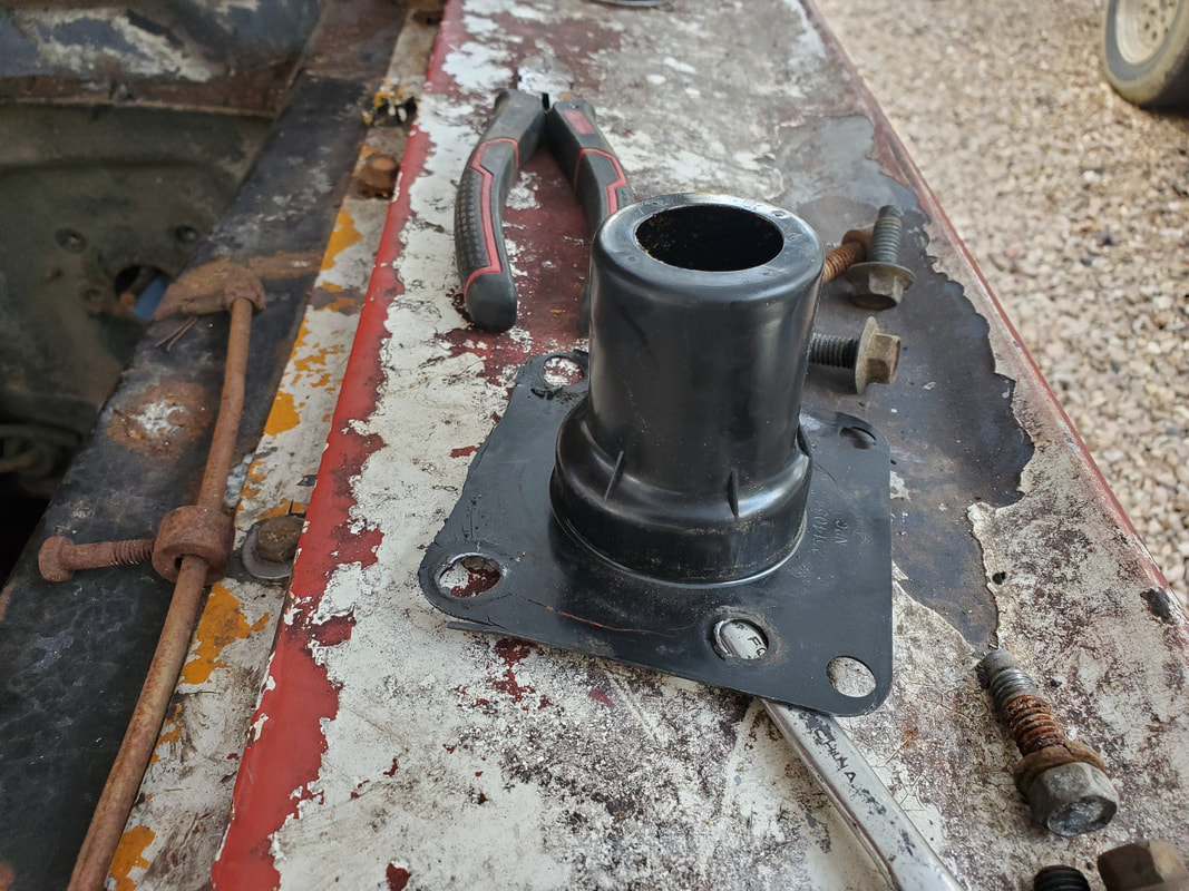 Plastic protective cover from rear of brake booster used to trace out the stud holes on the firewall. I did find the spacing on the bolt holes from left to right was the same on the firewall as on the booster. The vertical spacing wasn't. I had to drill two extra holes below the top two holes to get the desired spacing for the brake booster. I also had to remove the shaft that attaches to the brake pedal and goes to the old master cylinder. The shaft on the booster is not removeable, as far as I can see, so I would have to use the shaft on the booster, attached to the Mustang's brake pedal. I had to cut on the pedal bracket under the dash as the two bottom studs were close to the edges where it didn't allow me to install nuts to secure them. In the end I ended up only getting one of the bottom studs capped, along with the two top studs. I secured the pedal shaft along with the brake switch so all that is straight just as well. 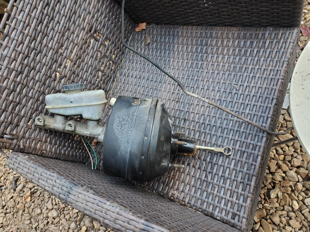 The junkyard Ranger brake booster/master cylinder, along with the integrated piston shaft. With the pedal hooked up, the studs capped, I verified that the top of the master cylinder would be low enough to not be hit by the hood. I also depressed the pedal to verify that things would still move properly as far as the pedal itself, the piston shaft on the booster, and the pedal bracket, making sure it wouldn't distort or otherwise move in an unconventional manner. With all that said and done, I also replaced the brake line going to the front brakes, as it was clogged. Unfortunately, I also needed to replace the line going to the rear from the master cylinder. This line stops at the proportioning valve and is also clogged. I'll have to hit the junkyard again to grab this brake line and install it. 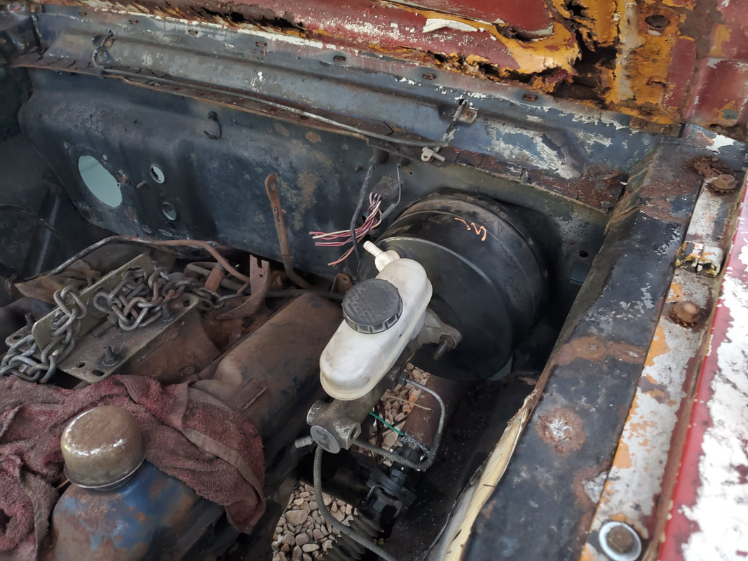 The Ranger master cylinder/brake booster installed on the Truckstang's firewall and fully hooked up, with one brake line installed as seen. Once I get the brake lines finalized, I can fill everything up and attempt to bleed the brake system. Hopefully I won't have to replace the calipers or wheel cylinders on any of the wheels. It's not that these components are expensive, it'll just suck having to source more little pieces for a system that was thought to be completed. But until then, I can move on to installing the miscellaneous engine parts that I have laying around. The biggest of these parts is the entire exhaust system.
After the initial coupling of the old Mustang steering hardware to the Ranger steering hardware, there was still a matter of getting everything tightened up. There was excessive play in the steering column tube at the firewall, as well as in the shaft where it couples to the Ranger coupling. I had to come up with a couple ideas to secure all this stuff best as I can, given what I'm working with. Of course, there's aftermarket hardware out there available to make these types of hybrid systems for hot rods and similar cars but as with everything else in this build, we don't really have much of an option to acquire these components, this type of hardware can get expensive.
So, the first thing that I needed to do was secure the column tube at the firewall. The easiest way i figured on doing this was to cut a piece of sheet metal in a U formation and loop it around the column, forcing it more to the center of the firewall. From here I'll secure the piece of sheet metal with sheet metal screws, through drilled holes in the piece and in the firewall. It wouldn't be perfect or pretty but it'll be functional and still allow things to be pulled apart when needed. 
The retainer plate cut from scrap sheet metal to be screwed in place on the firewall to hold the column tube stationary in the firewall.
The sheet metal piece for the column tube was the easy part. The next thing is trying to secure the steering shaft at the outer end of the tube. Since this tube is literally just a tube, I would end up having to weld something in place to hold the shaft in place. I'll also have to accommodate the shaft in a way where it can rest nicely and still be able to rotate without adding unnecessary wear on the shaft. What I ended up with was taking a washer that was almost the same diameter as the inner diameter of the steering tube and a piece of 3/4" conduit and welding the two together. The conduit has almost the same inner diameter as the outer diameter of the steering shaft. After welding the two pieces together, I slid the assembly over the end of the shaft and held it in place, adding a couple tack welds to hold everything together to do a final fitting before doing the full weld. 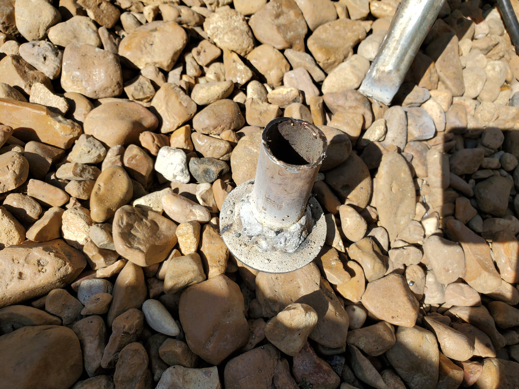
The piece of conduit and washer welded together to make up the bushing assembly that will be welded in place at the end of the column tube.
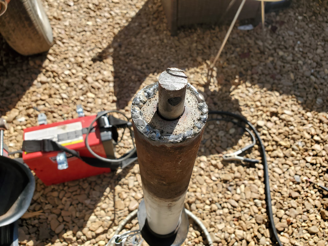
Bushing welded in on the end of the steering column tube with the shaft protruding from the bushing for test fitting purposes.
With the end of the steering shaft fixed up, I reassembled the column in the car, securing the U-shaped sheet metal retainer piece first. From there I put the steering shaft/wheel back in place and added the Ranger coupling after sliding the end of the shaft through conduit bushing. Once everything was fully secured, I was able to steering the wheel without everything flopping around like before. 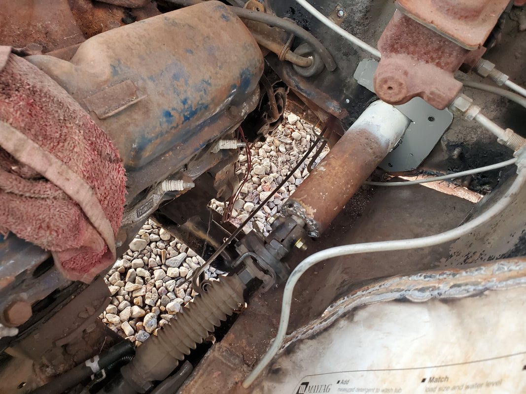
The completed steering coupling/column/bushing assembly. Note how the plate is bolted in place along with the welded in bushing.
Even with all this in place, the whole assembly isn't perfectly solid. There's still a minute bit of play at the coupling/firewall area, but nothing near as serious as before. The wheel is able to be turned with a level of sturdiness that should allow the car to track without excessive play that would cause excessive sway/drifting. I will have to replace the bushing in the steering column tube at the turn signal cam because that is worn out enough to have excessive play. It doesn't affect things at the coupling but replacing this component will go a long way towards making the steering system more solid.
One of the bigger subsections of this project that I had some concerns with was the steering. For one, the old steering was made up where the old gearbox had the steering shaft integrated with the unit. I would have to cut off the shaft in order to use it with our new hybrid steering. Plus, where the steering column tube sits puts if off center from the Ranger steering gearbox. Luckily the coupling that I sourced from the junkyard Ranger has these rag joints that kind of allow for some flexibility, in much the same way as universal joints work. I still have to mount the steering column tube and trim it down as the length of the tube will more than likely go past where the Ranger steering coupling goes. I also had to get the column tube bracket/hanger in place to be able to hang the unit. 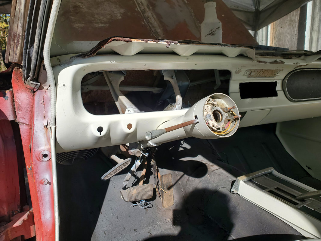 Steering column tube mounted in place for initial fitment. With the steering column in place, the next move was to chop the steering shaft from the old gearbox. While some would ask, "why destroy a perfectly good steering gearbox assembly?" Well, to replace this with a standalone steering shaft would cost more than what I could realistically get for this gearbox if I were to sell it as a used/core unit. Plus, these integrated units are available all over as is the conversion hardware to convert to a separated steering shaft/gearbox setup. So yep, this thing's getting cut up. 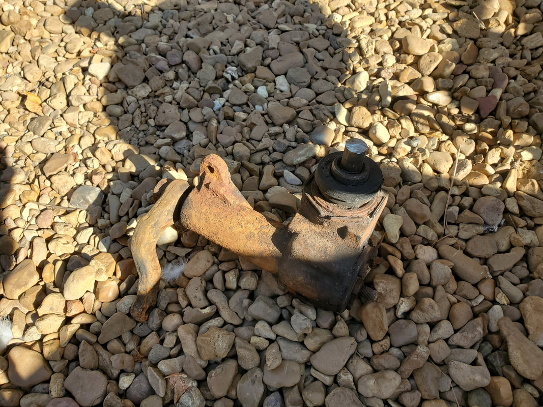 Old steering gearbox after chopping off the integrated steering shaft. 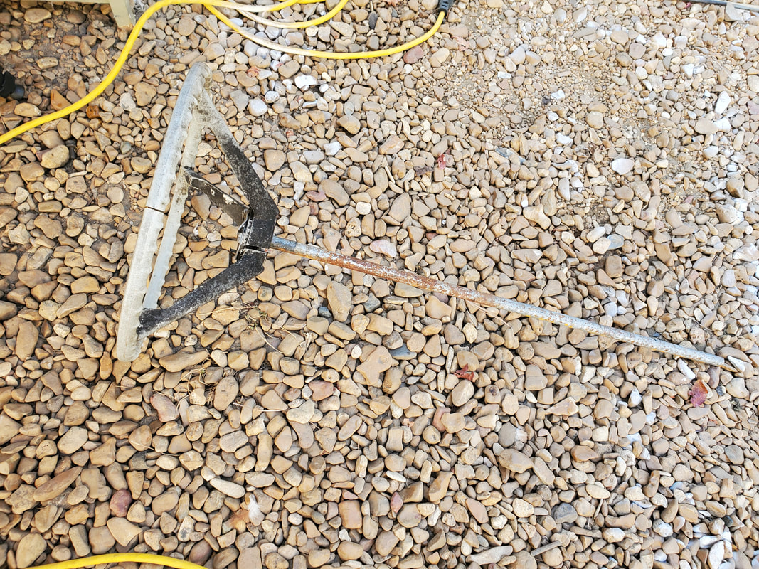 Steering shaft attached to steering wheel with retaining nut on end of shaft. From this point on, these two pieces will remain integrated during the whole building process for the steering system. I did try to "measure" the whole works by inserting the steering shaft from the inside to see where it sat to get an idea of just how much I'd have to chop off. In the end I found that I would damn near need to chop all of the shaft from the gearbox. I did leave about an inch and a half of stub on the gearbox, mainly because I may find some kind of weird automotive project to build incorporating this old gearbox and having that stub will allow me to couple some form of steering coupling to it. So yep, this old gearbox won't be scrapped, yet. It just depends on whether I can figure out something interesting to build using this part before I do end up doing a mass scrap-off. I also took the time to secure the steering wheel to the end of the shaft using the retaining nut so I can more easily test fit things and not have to worry about components separating in the process. One of the next things I had to do was chop the column tube. After reinserting the steering wheel/shaft and measuring where the end of the shaft sat in the tube, I cut off enough of the column tube to allow for about two inches of the shaft to protrude from the end of the tube. This will allow me to more easily couple the Ranger steering coupling to the end of the Mustang steering shaft. After another test fitting, I found I had to slide the steering column tube down through the firewall and closer to where the steering coupling sat. In order to secure the tube, I had to drill another hole that the bracket fits into to hold the column tube in place. After doing this, I had the tube sitting further into the firewall. This of course put the steering wheel closer to the dash, which was fine, as long as I got the coupling secured to the end of the shaft. With that all said and done, I had to drill a hole in the end of the shaft to accommodate the retaining bolt on the coupling that would hold it to the steering column shaft. With a series of drill bits going from small to largest, being a little over 5/16", I managed to get a hole drilled in the end of the shaft. I did take a moment to line the steering wheel up where it would be straight along with the wheels to maintain some sort of alignment. 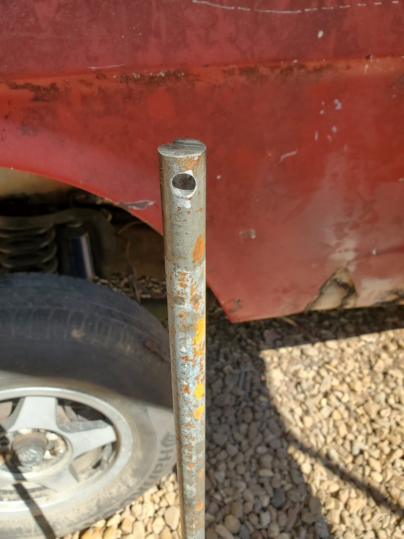 5/16" hole drilled through the end of the steering shaft to accommodate the bolt in the Ranger steering coupling. With the hole in the end of the shaft, I removed the larger 3/8 bolt from the Ranger steering coupling and replaced it with a grade 8 5/16" bolt. Reason for this is because the Mustang steering shaft is only so wide, widening the hole to accommodate a 3/8" bolt would have the walls around the hole thinner, which could put the shaft at risk of cracking/breaking around the hole, which could lead to a catastrophic failure at the worst possible time. By using a grade 8 bolt, I'll have the strength to maintain a coupling between the Ranger coupling and Mustang steering shaft.  Ranger steering coupling and Mustang shaft integrated with the grade 8 bolt. Also note the end of the column tube on the right of the picture. With the coupling and steering shaft together, I did a successful test turning of the wheel and the steering system as a whole. Everything turned as intended. With working power steering everything should work like a charm. Of course the biggest problem that we have here is the idea that there is no kind of bushing or bearing in the end of the column tube to support the outside end of the steering shaft. This allows for excessive play in the length of the steering system, which is not a desirable thing. I'll have to figure out some kind of bushing or find some kind of bearing that I can work into or on to the end of the steering column tube to cradle the shaft. I'll also have to find some kind of way to provide for an anchor on the firewall to hold the column tube stationary at the firewall, but offset to the right. This will allow for the steering shaft to be somewhat closer to centered with the Ranger steering coupling in order to put less of an angle on the rag joint at that end of the coupling. 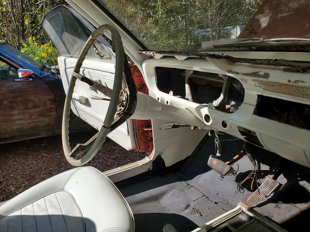 Steering column at new position with wheel and shaft in place after successfully coupling the hardware together. While everything may appear fine right now, repeated use will inevitably wear everything out to where there would be excessive play in the steering. Getting everything anchored down now will go a long way towards maintaining a solid and long lasting steering system that integrates old and new in this build. Of course I also took a moment to spray down the components, only leaving the steering wheel. I might remove the wheel and hit that too, then again I may not, depends on if I have another idea for that. At this point, I'm about near the end of the interior restoration part of the project. I had already spray painted the seats and had to let them sit for a few days as the material did not take the paint as well as other body parts. As a result, the material remained tacky and was still tacky even up to this point as I finished up things on the interior. I also stripped the dash body of the remaining switches and other materials in order to prepare to paint that surface. I also had to remove the door panels and window crank/door release lever so I could spray the insides of the doors. At this point, I gave the dash a shoot down of paint and while the first coat was curing, I started prepping the doors and the door panels for their spray down as well. 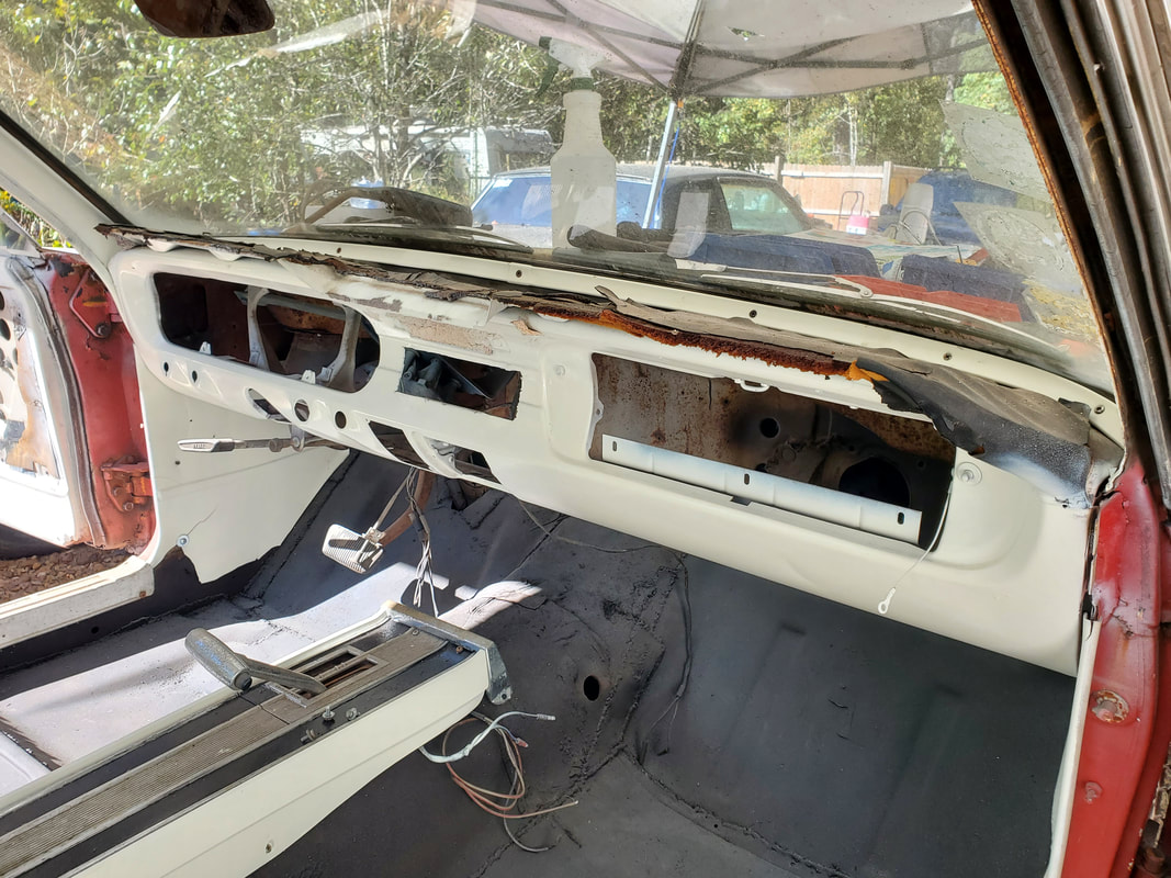 Dash body sprayed down with paint. I will have to source a dash pad to cover the areas where the old dash pad was in order to fully restore the dash. I added some newspaper to the top of the doors to cover the window glass. I could've lowered the window but because of the panel being removed, the glass would've taken paint through the open middle of the door panel anyway. Plus, there was also a matter of the vent window, so all of this had to be masked off. I also had to wash the door panels to rid them of old dirt then let the panels sit in the sun while I came back to the dash to hit it with a second coat. 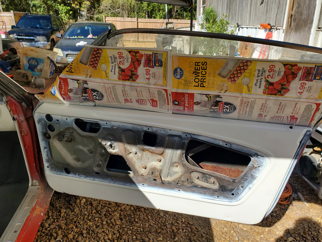 Passenger side door with masking tape and first coat of paint applied. 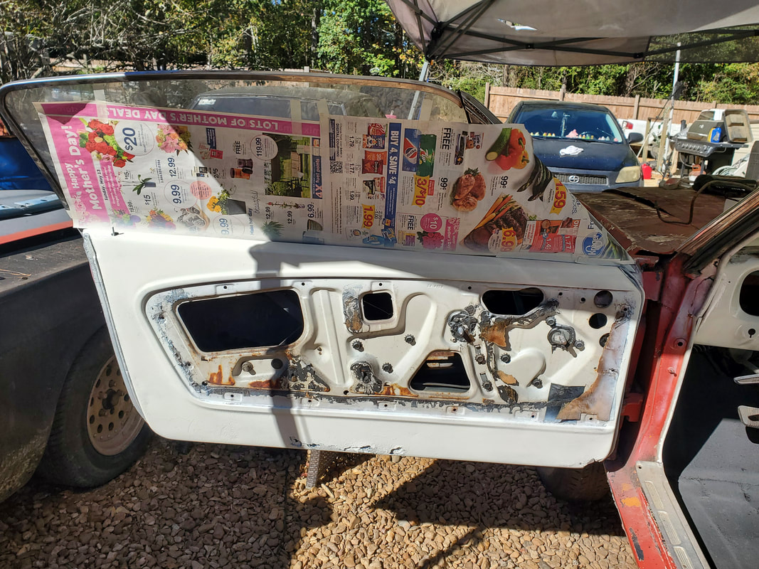 Driver's side door masked off and spray painted with first coat of paint. After cleaning the door panels I also had to mask off the trim on the middle of the panels. This material has a chrome plated finish so to let this get sprayed over would be a disservice to the design of the interior. I laid some masking tape down along the length of the trim, then used a box cutter to cut the excess tape on either side of the trim, leaving just the trim pieces with tape over them. With that, I was able to spray the panels down. Sitting in the sun, the paint cured that much faster, allowing me to lay a couple coats down in short order, allowing me to also start on the doors. 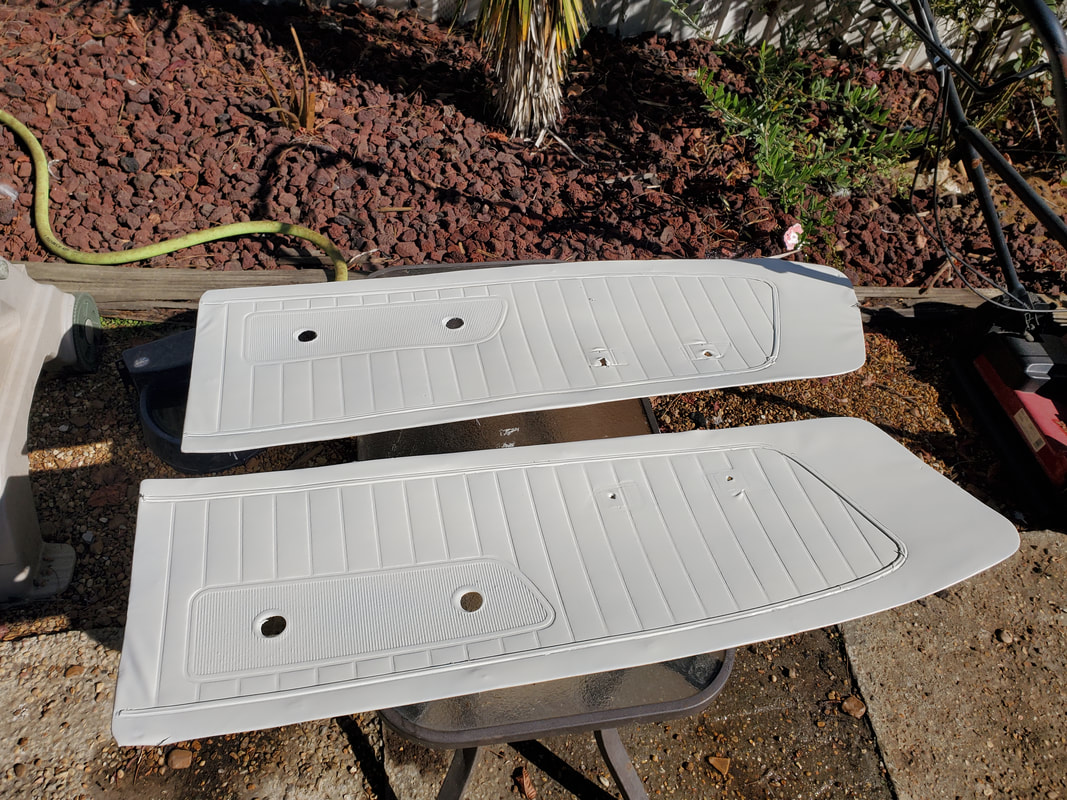 Door panels after spray painting them with a couple coats of paint. Chrome plated trim around the middle of the panels is covered in masking tape. In the process of spraying these panels and letting them sit prior to applying a second coat, I also shot paint on the doors, all around the inside and the edges where the surface used to be white. Even though there are rusted out areas, after sanding the doors down, laying paint on the doors will go a long way towards making the doors and the interior as a whole look a lot better. 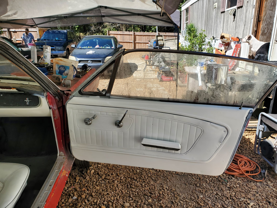 Passenger side door painted up with door panel installed along with window crank and door release lever. I only had one armrest on for this door, but I took a moment to paint it up before reinstalling it on the door. 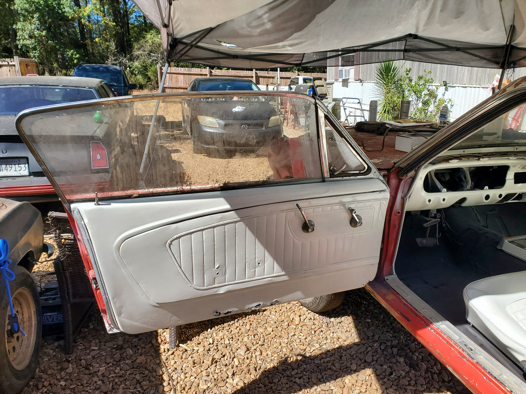 Driver's side door with the masking paper off and window crank/door release levers installed over the door panel. Once the doors dried out along with the panels, I remounted the panels, which resulted in me having to touch up the points where my fingers left a little dirt. That's the only thing that sucks about using white paint, any kind of contact runs the risk of flawing the surface. With the panels back on the doors, I put the window cranks and door release levers and ripped off the masking paper to conclude the "restoration" of the doors. With all that said and done, I decided to go ahead and mount the seats. They were still a little tacky but not so bad that they couldn't be handled. Since I already fixed the mounting studs, I went ahead and set them down and bolted them in place.  The interior with the seats in place. With the seats in place, the interior is pretty much done. As for the dash, I won't put the switches or anything else back in until I start the rewiring, since well, the switches need to be rewired in place. I did take a moment to put the glove box door back on but that's about it. The next order of business will be the steering system. I have to install the steering column, which is a simple tube with the turn signal cam and some wiring. The steering shaft, which is part of the old gearbox, will need to be cut off then hooked up to the steering coupling that I picked up from the junkyard. Up next, the steering! |
