|
After really thinking about things, I decided to implement a new plan regarding the chicken yard. Since we got the main gates up, we pretty much turned the birds loose across the whole yard. While this is fine, the time will be coming to start planting and these assholes are all over the garden. Plus there is still the threat of air attack against the birds. The plan I have is going to be to move the fences on the west and east ends of the garden in closer to the car and cab coops then create a screened front wall along the front of the car coops, and topping everything off with large chicken wire fencing along the top, supported on a frame, creating a structure that will be part aviary and part shed/canopy. The rear section, set up along the north fence, would have corrugated sheet metal reaching out 6ft to create a covering that would allow for setting up things like bulk feeders, nest boxes and roosting posts, among other things. The vision is pretty colorful in my mind. 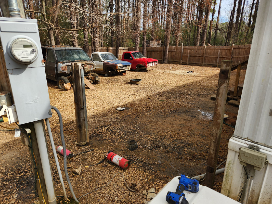 A shot from outside the chicken yard looking in after dismantling the fence and gates. 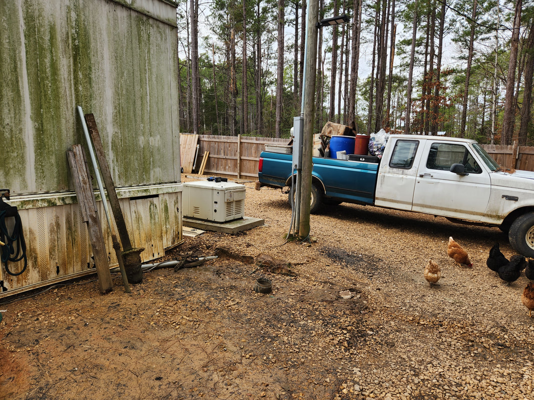 A shot from the chicken yard looking out, with the old fence posts pulled up just as well. Note how the uneven ground wore around the old fence line. With these plants set into motion, obviously I'll be dismantling the west chicken yard fence, including the gates. I started off with the removal of the short section of fence that connected to the house and to the gate post. The ground in this area was eroding anyway and the fence posts were already unstable so it was just as well that this fence is coming down. Another thing I thought about was the issue with the main gates. Since we used off the shelf fence panels for gates, this created the problem of one of the panels warping. Even with the support of the caster wheel and tension wire and braces, the 2x4's that make up the panel started bending unevenly, causing the panel to twist oddly, creating unsightly gaps and making the gate sag and drag and be a bear to open at times. Something had to be done about that, and this is where the old chicken yard gate comes in. 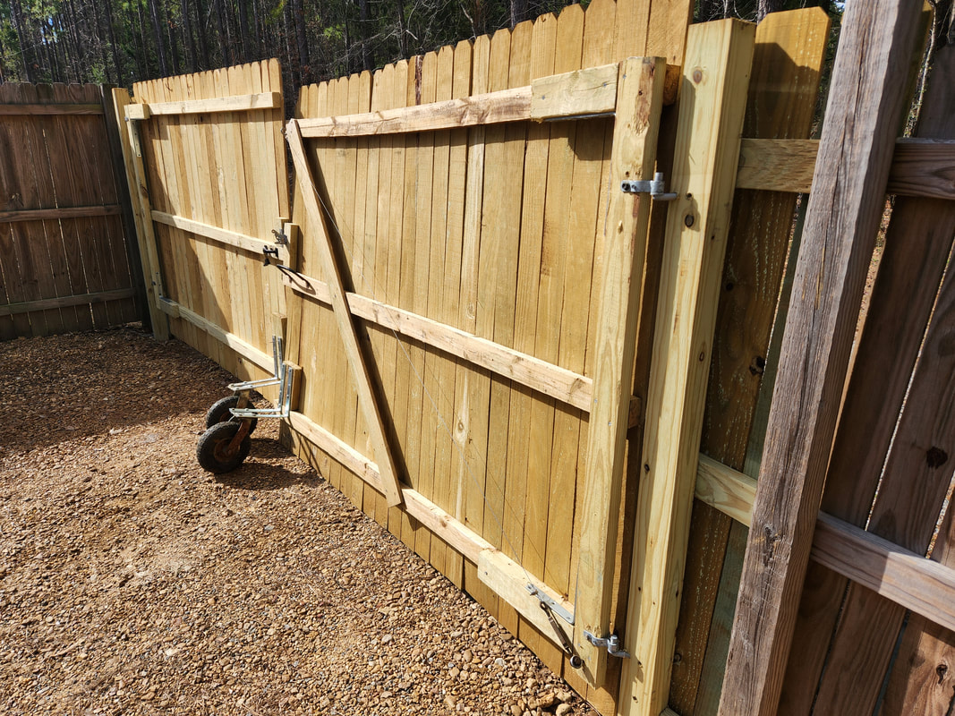 The right side gate showing the apparent twisting and warping. Note the extra board that was used to try and cancel out the warping of the panel. 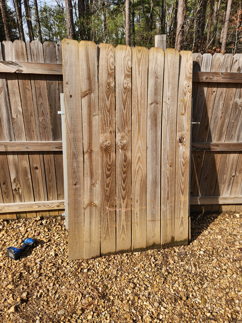 One of the chicken yard gates staged on the west fence, ready for disassembly to be used for our new main gate. The plan will be to disassemble one of the gates, using the gate kit to build a long gate to span the length of the old gate, which is around 90". There are tubes that connect the two ends to give the gate support, but these tubes won't reach the whole 90". I'll have to take three of the four tubes from this kit to make a span for the top and use some round tube from the scrap pile to do the same thing on the bottom end. 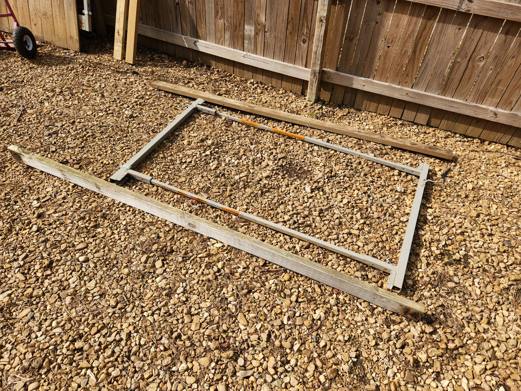 The gate is disassembled and set up, staging for reassembly as a longer main gate. A couple of 2x4a from the old fence panel are also staged with the gate kit to be trimmed accordingly. At least this gate kit will be stronger and less prone to distortion unlike the unseasoned wood in the fence panel, and it will be lighter too. If all things work out I may even do the other gate panel the same way with the other gate kit left over from the chicken yard. More to come on this.
0 Comments
After having to constantly open the main gates in order to just walk outside for any given reason, I decided that an entry door of some sort would be appropriate to allow for foot traffic so the main gate can remain untouched during all those episodes. What I did decide on was to use a part of the existing fence to construct the door. This would involve sinking another post across from a corner post where I will be making the door. From there I'll cut out the section of fence, creating an opening that will then be closed in with the constructed door, which isn't as simple as just slapping some hinges on the gate panel. 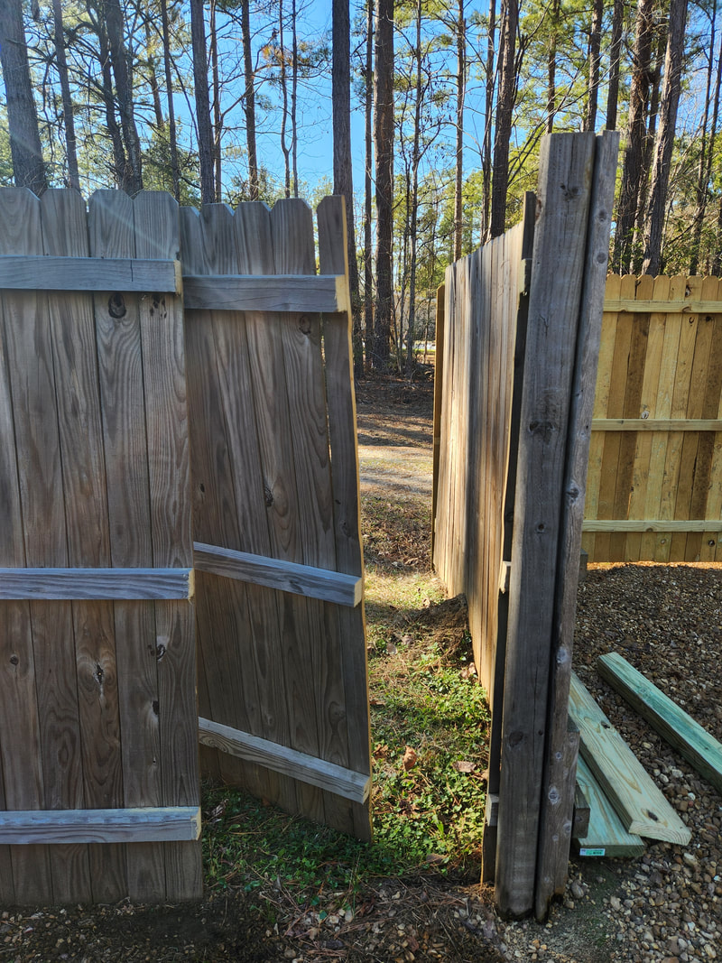 A section of fence is cut out from the main panel to create the door and give me the ability to move the fixed panel out of the way a little so I can auger drill the post hole. 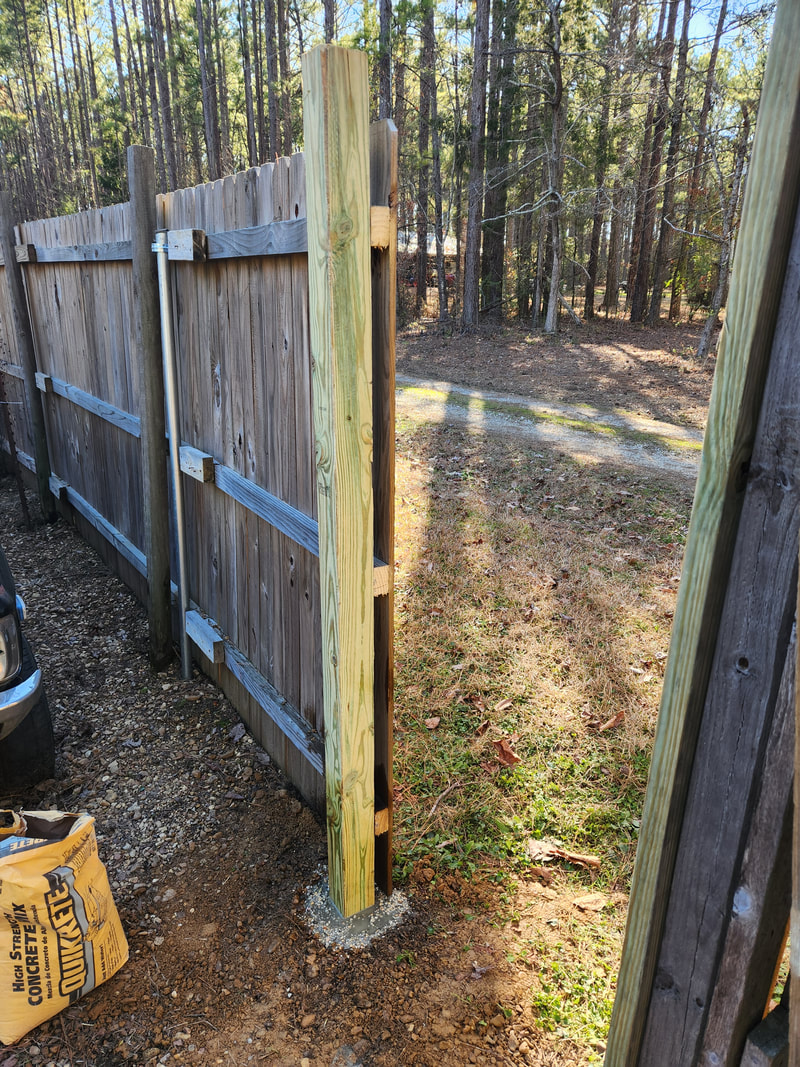 After drilling the hole in the ground I added the post and dry poured the concrete, soaking the powder with water. This method is a lot easier than premixing the concrete then trying to spread the soupy mix into the narrow spaces between the post and the walls of the hole. The first thing I did after securing the end of the fence to the new post was take a section of 2x8 board, cut to 6ft, and secure it to the post and to the ends of the 2x4's on the fixed fence panel. This will create the backing that will hold the hinges to the door. I also took the section of fence and attached a 6ft length of 2x4 to one end. This end will be the hinged end. 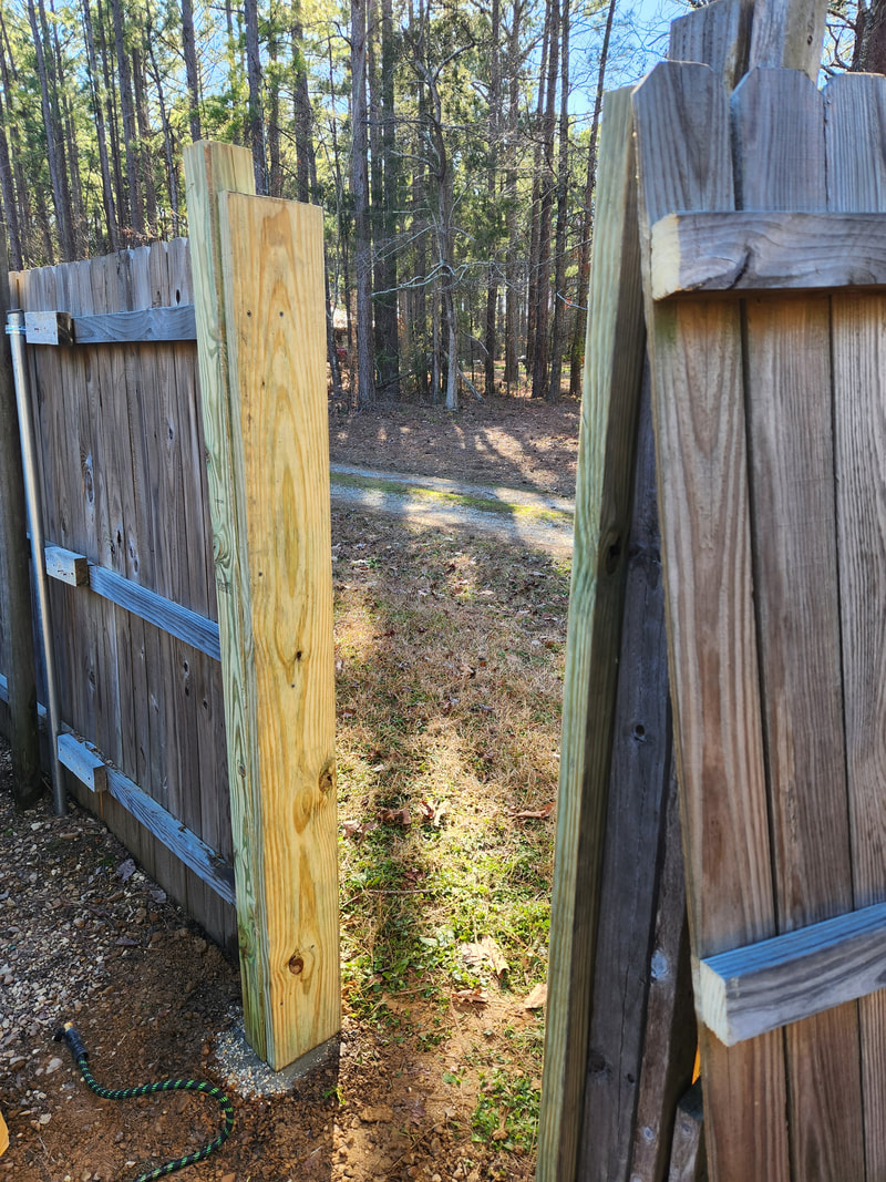 A ft length of 2x8 is secured with deck screws to ensure super strength for supporting the door. The same is done for the other side, which will serve as the latch base. With the board on the panel I attached the hinges, hanging the panel in place. I added another 6ft length of 2x8 to the other side of the opening, against the corner post. This side will be the latching side for the door knob. To keep this side from swaying due to the fact that the post is weak at the base, I added a 2x4 across the top. Since the posts are topping at a little more than 6ft, there's no threat to either of us hitting our heads coming through this opening, can't say the same for anyone taller than 6ft. I ended up having to trim the fence panel turned door so I can add another 6ft length of 2x4 to the other end of the panel and be able to close the door with the latch end being flush with the door. This is to ensure the latch on the door knob catches solidly. 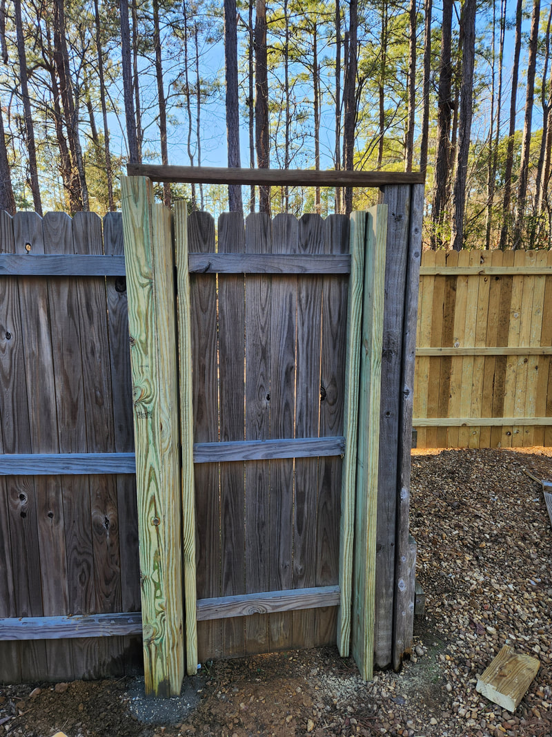 After adding a 6ft length of 2x4 to one side of the cut fence panel piece, the panel is hung with three large hinges. Afterward, measurements were taken to trim the excess from the panel, allowing me to add another 6ft 2x4 to the other side of the panel and be able to close the door properly with minimum gap between the 2x4 and 2x8 boards. Another 2x4 is added across the top to add rigidity to the latch side of the fence as the post there is weak at the base. Now this is where the meat and potatoes comes in. I had to start fitting the door knob in this oddball location, which was never intended to accommodate a door knob. I started off with drilling a hole with a spade drill bit to accommodate the latch. From there I drilled another shallow hole in the 2x8 and attached the plate for the latch, testing that to ensure things caught solidly. Next I started fitting the door knobs, looking at what I would have to add to allow me to install the door knob assembly close to the proper way it was designed to be installed. 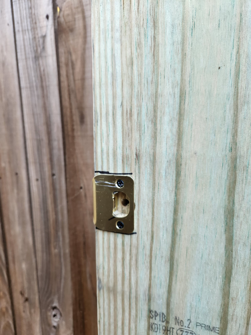 A shallow hole is drilled into the latch base board and the plate secured in place with its included screws. 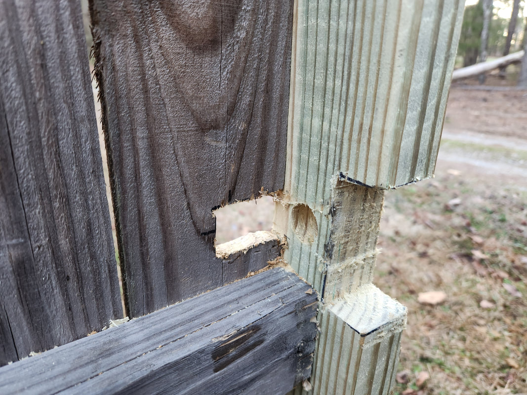 The 2x4 has a notch cut out of it to allow for clearance of the door knob when its installed. The hole for the latch mechanism is also added and the beginning of the hole for the door knob is cut in the fence picket on the door. 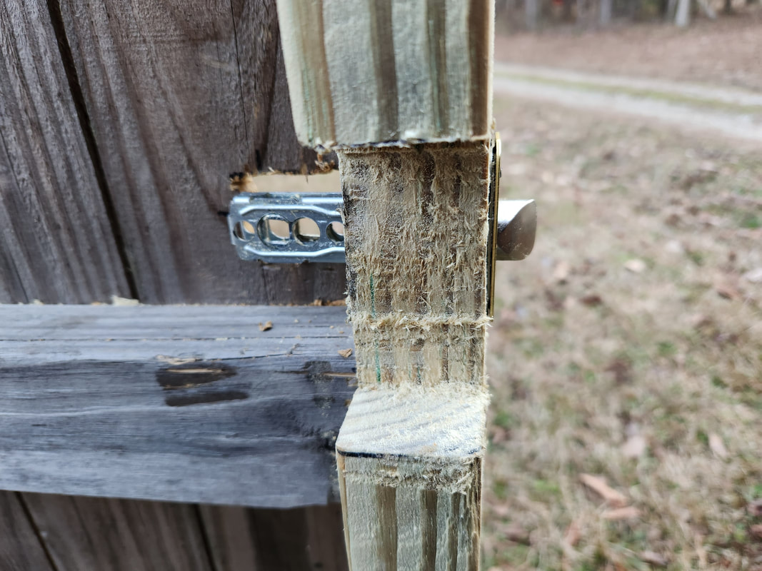 The latch mechanism is added to the 2x4 and secured with its included screws. After some fitting I found that I would have to cut and install a piece of 2x wood, cut from a salvaged piece of 2x6 This piece would have a notch cut out that will accommodate the door knob mechanism which has to rotate in the opening, while also accommodating the latch mechanism. Later on to get both sides of the door knob to meet flush with each other, I had to cut a circular hole in the picket on the outside of the door, allowing the lock end of the door knob base to be recessed into the hole. This brought the outer half of the door knob close enough to allow the inner half to meet all the way while against the cut 2x board. With some minor adjustments, I got the door knob/latch to operate smoothly while latching solidly. 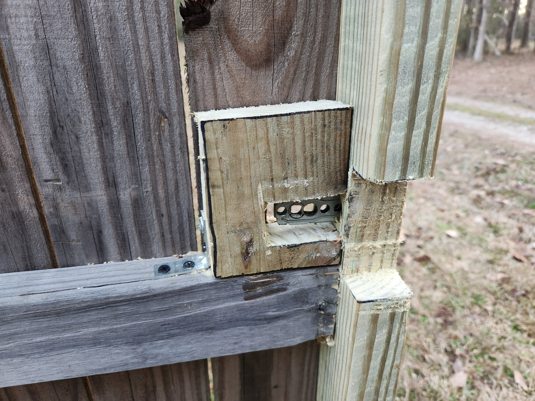 A piece of wood cut from a salvaged 2x6 is cut to fit the door knob assembly inside the area where the latch mechanism is located. This board will go in and out several times before the openings are cut to a satisfactory size to accommodate the door knob internals. The block is held in place with wood screws from the outside while being held with a small angle brace on the inside. 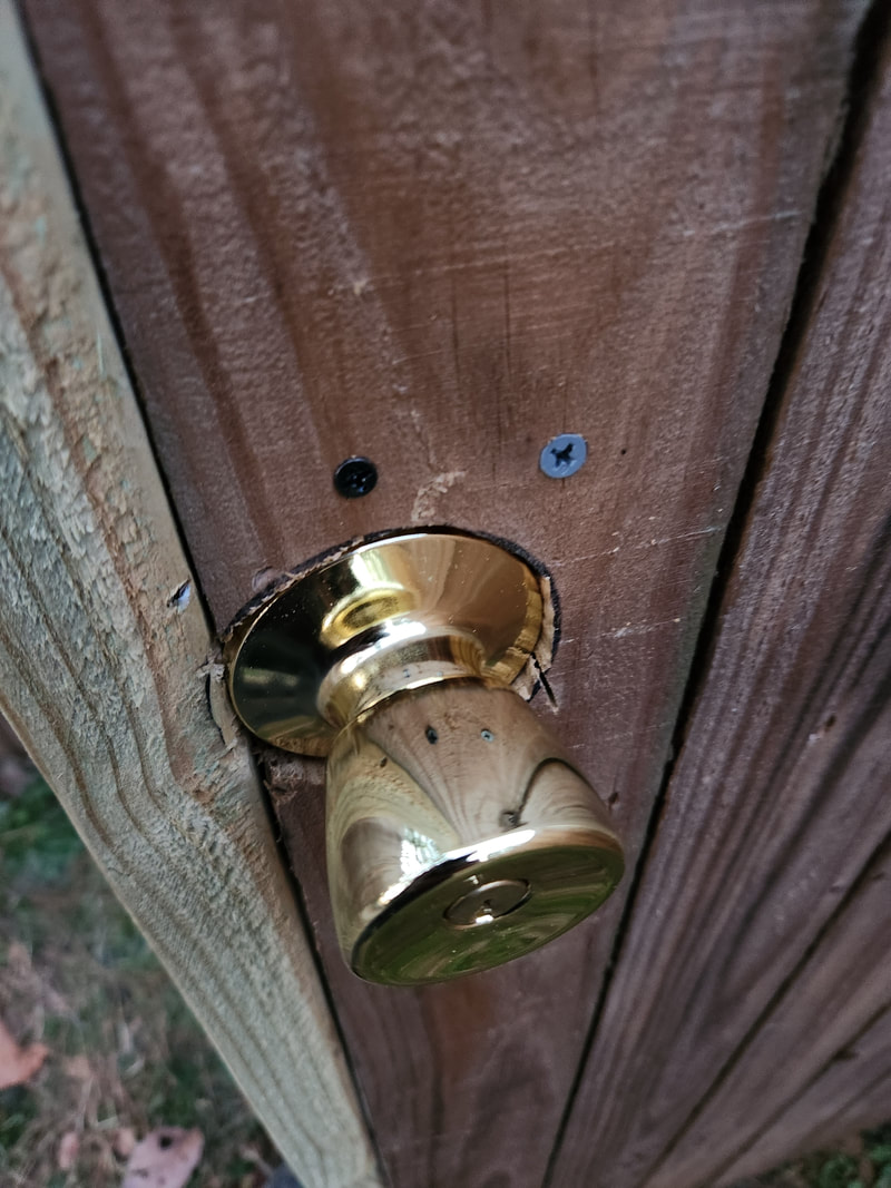 Fitting the outer half of the door knob into the hole. After multiple cuts to open up the hole on the picket, the door knob is mounted in a partially recessed position in the hole. Note the two screws above the door knob that are holding the 2x block in place. 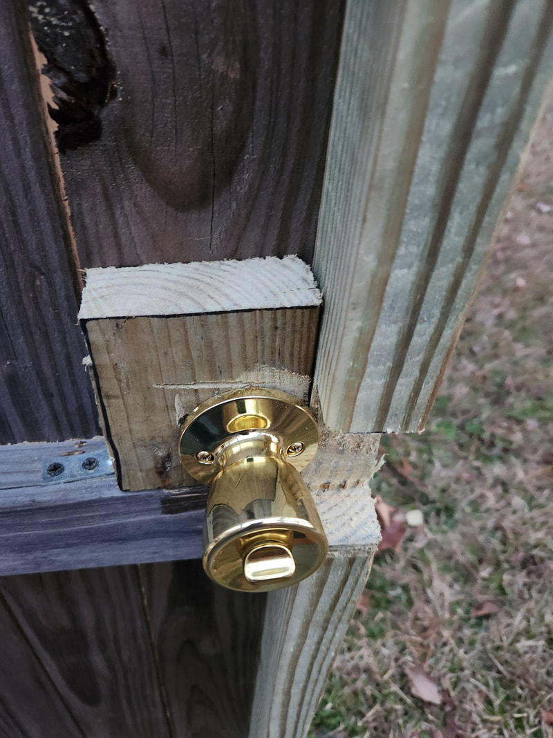 The inner half of the door knob is in place, flush against the 2x block and fully screwed down to the outer half of the door knob. Note the angle brace holding the block on the left. 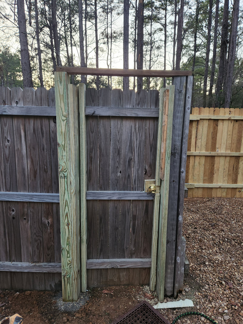 The completed door assembly with fully functional locking door knob and support, ready for service. With the new gate door completed, we can now move in and out smoothly, especially if we're already outside of the gate and need to go back in for something last minute. There's no need to fight the gate just to run in and grab a hat. With the door I will also be spreading gravel to create a path in front of the door going to the road, as well as creating an embankment so we don't have the dip right at the side of the road that can be wet when it rains. I can also add a light and even a doorbell camera. I will also look at relocating the package drop off crate and signs to the other side of the door, keeping things nice and close together. After trying to troubleshoot what might be going on with the Scion's apparent loss of coolant and subsequent overheating, I finally started seeing the clues that lead me to the idea that the head gasket was bad. With fresh coolant in the rad, upon starting the engine, the coolant started frothing with air bubbles, indicating a break between the combustion chambers and cooling jacket, probably small enough not to allow water to seep into the combustion chamber, but enough to allow the pressurized hot gases to blow out into the cooling system. Either way, the engine has to come apart in order to replace the head gasket. At the same time the timing chain and hardware have to come apart so I may as well replace that hardware too. First thing's first, I had to drain the fluids and start removing stuff from around the engine. 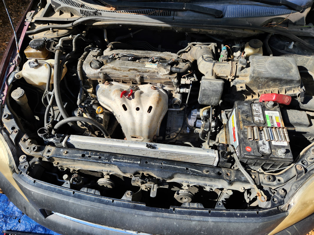 As was the case with the engine replacement, a lot of wiring and hoses have to be removed along with large hardware. 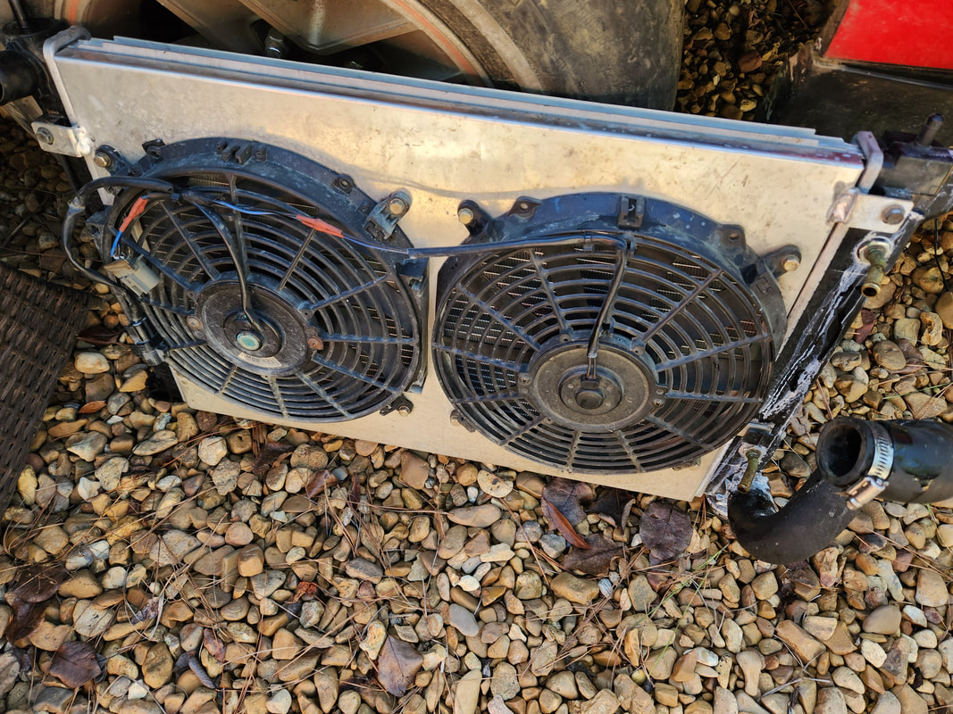 I took care to remove the radiator with the fans still attached so I can spare myself the headache of resecuring the fans during reassembly. With the radiator removed, the next thing I had to pull off was the serpentine belt. This had me having to go under the car to route the belt from around the power steering pump. I also had to pull the cover off the exhaust manifold to remove the nuts holding the piece on. To get one of the nuts off I had to remove the alternator. Once the exhaust was out I pulled the air cleaner box and started removing wiring, taking a moment to mark the plugs with tape showing the particular load written on the piece. 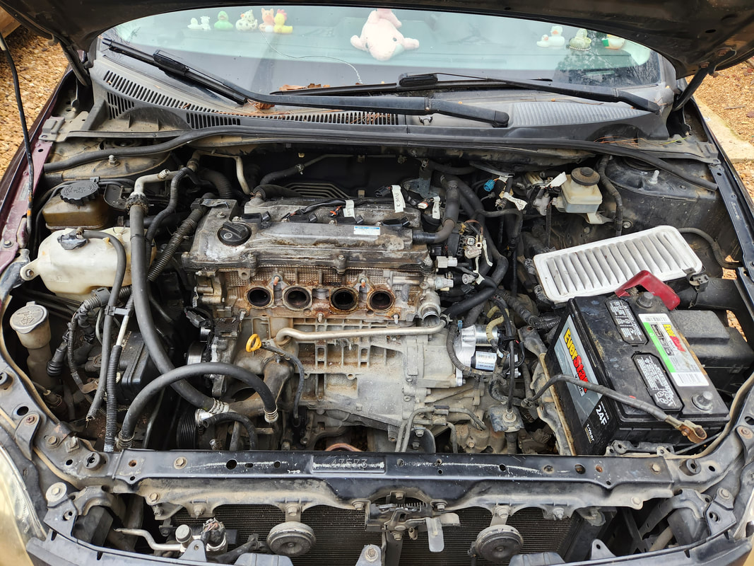 The engine sans exhaust, air box, and alternator. Several wires are marked as well. 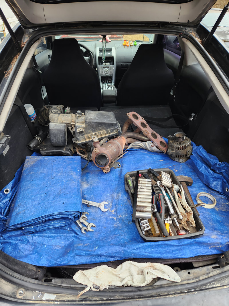 Our parts collection continues to grow... We're off to a start, but with a job like this, I'm going to be taking my time, same as I did with the engine swap. I still have to remove the fuel rail and those plugs, as well as the intake manifold. I also have to pull the coils and valve cover so I can get the head bolts pulled. I got new head bolts with the gasket kit so there won't be any concern with saving or even noting the position of the old head bolts for reuse. I will have to see how to hold the engine still to pull the crank pulley as well and afterward note where all the timing cover bolts are so they can be removed to get that part off. That's one of the biggest things I hate about transverse mounted engines in FWD cars. The work will continue, slowly but surely so the chance of messing up something is lessened. With the old Ford fuel sending unit not working properly, I had to order an aftermarket unit to use on the FMT's fuel tank. Only problem is I don't want to have to cut another hole in the fuel tank, especially since the tank still has fuel inside. The only other option is to modify the old sending unit yet again to accommodate the new sending unit. Really what I'm doing is salvaging the base and somehow merging the two together. What this entailed was cutting out the old stuff, including the fuel line tubes from the base. One of the tubes will be used as the pickup tube but the other one is not needed. I ended up using a rotary tool to cut out the metal around the fuel tube and also a large hole around where the new sending unit base will be mounted to. I drilled holes around this large hole for the mounting holes on the new sending unit. I also drilled another large hole off center to accommodate the fuel tube. 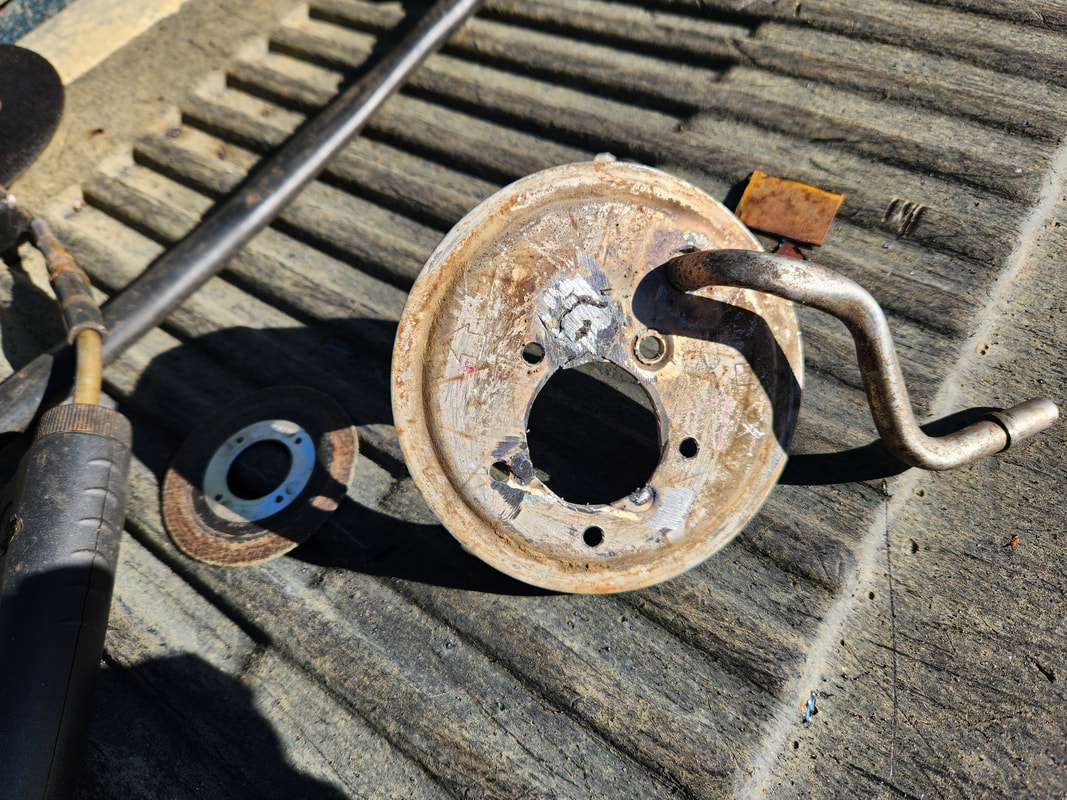 A plug had to be welded in place to cover up the hole made from cutting out one of the fuel tubes during the modification of the sending unit. Our other fuel tube is already welded in place after clocking it to point forward when the sending unit is mounted in the fuel tank. After getting the base hole set up for the new sending unit I had to weld a plug over the remaining hole from where the other fuel tube was. Once that was welded shut I ground down the slag to smooth things out then took the fuel tube we'll be using and clocked its output line based on where the sending unit base sat on the fuel tank. This was so when the base is secured, the output would be pointing forward and not backward or to the side too much. Once that was established I welded the fuel tube in place using the surrounding metal that I cut out with the tube as an attachment point so the welding won't damage the fuel tube itself. 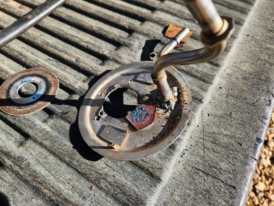 A shot from the underside of the base shows the scrap metal plug welded in place along with the fuel tube where the surrounding metal was used as an attachment point for the welding slag during the welding process so the fuel tube itself wasn't damaged by the weld arc. With the plug in and the fuel tube welded in place I was able to bolt down the new sending unit on our modified base, using small nuts and bolts that came with the sending unit. From there I took the wiring harness from the old sending unit and crimped a fork terminal and secured it to one of the mounting bolts on the new sending unit and a ring terminal on the positive side which was secured to the terminal on the sending unit. This allowed me to test out the sending unit with out multi guage cluster to see how to calibrate the gauge to the sending unit. 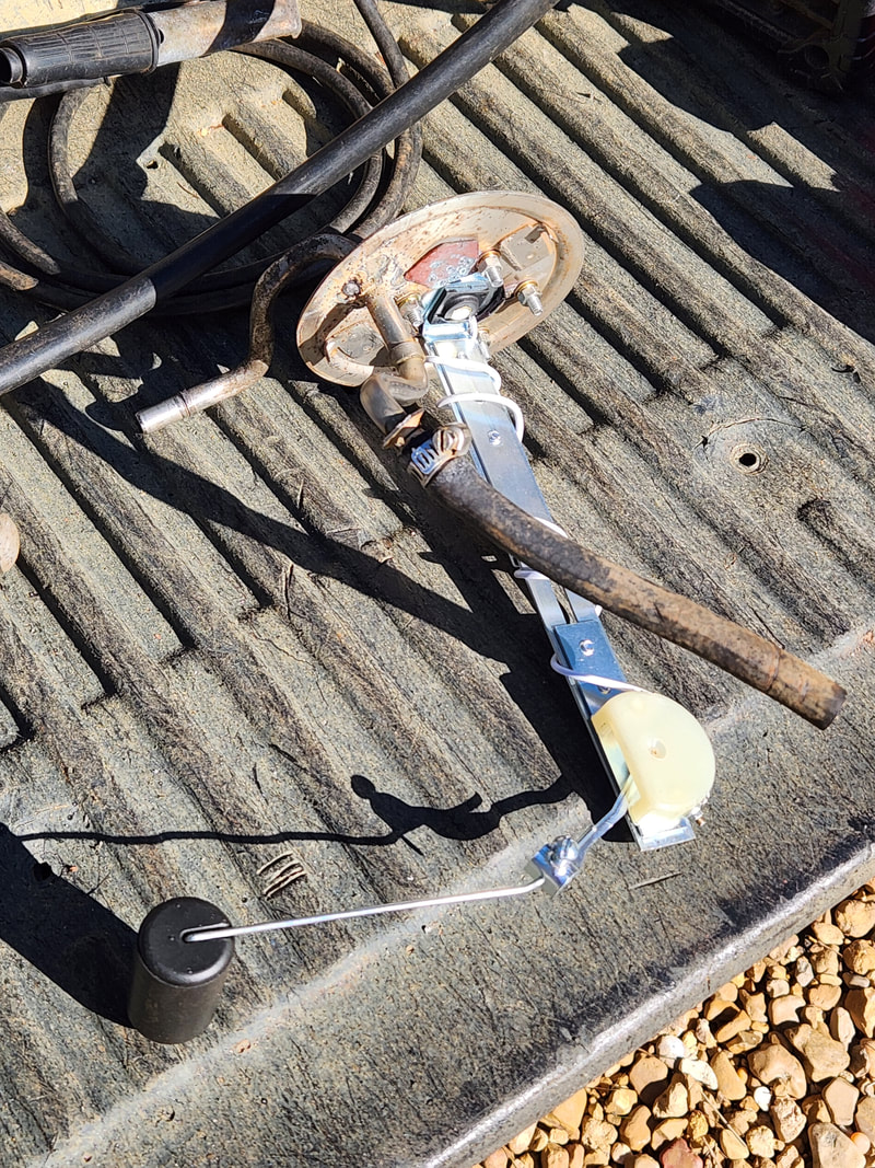 The new sending unit is secured to the old sending unit base, along with the fuel pickup hose that's clamped to the tube in the base. 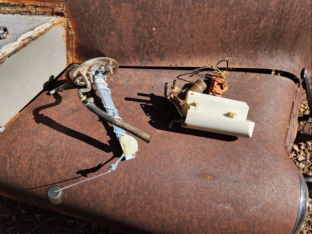 With the modified sending unit complete, the extra hardware to the right can be trashed as its no longer needed. 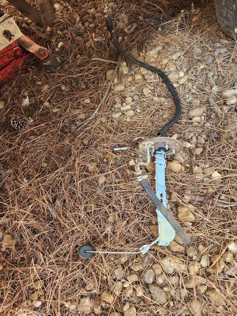 The modified sending unit is plugged up to the truck wiring harness for testing/calibration with the multi gauge cluster. After playing around with the gauge settings I ended up finding that the best setting that was available on the gauge was one where full reads around 63% full and 0% when the float is around the 1/3 to 1/4 full level. While this is pretty bootleg in its operation, it's kind of idiot proof. When the tank is full its going to read in that 60% ish range for a while. As the level goes down the number will go down and by the time the gauge reads 0%, letting you know its time to fill up, you can still rest easy knowing you still have about 1/3 to 1/4 tank of reserve fuel to get to the petrol station to refuel. There's really no risk of running dry when the gauge hits 0 at this point. 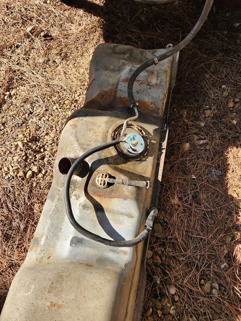 The modified fuel sending unit is secured in the stock fuel tank and ready for remounting under the truck. With that taken care of, I was able to go ahead and remount the new sending unit assembly back into the tank and remount the tank so later on I can start dumping fuel into the thing and real time test the gauge as well as get the engine back up so we can start really putting this truck on the road for more extensive testing. The next thing that I had to do on the front of the body was add the valance panel. I had to loosen the bolts on the fenders to allow me to reposition the two panels to allow for mounting of the valance panel as close to even as possible with the bottom fronts of the fenders. I did have to bend the bottom tabs on the valance panel since the front of the truck frame was interfering with the placement of the panel. By bending the panel i was able to get the piece positioned as close to home as possible. 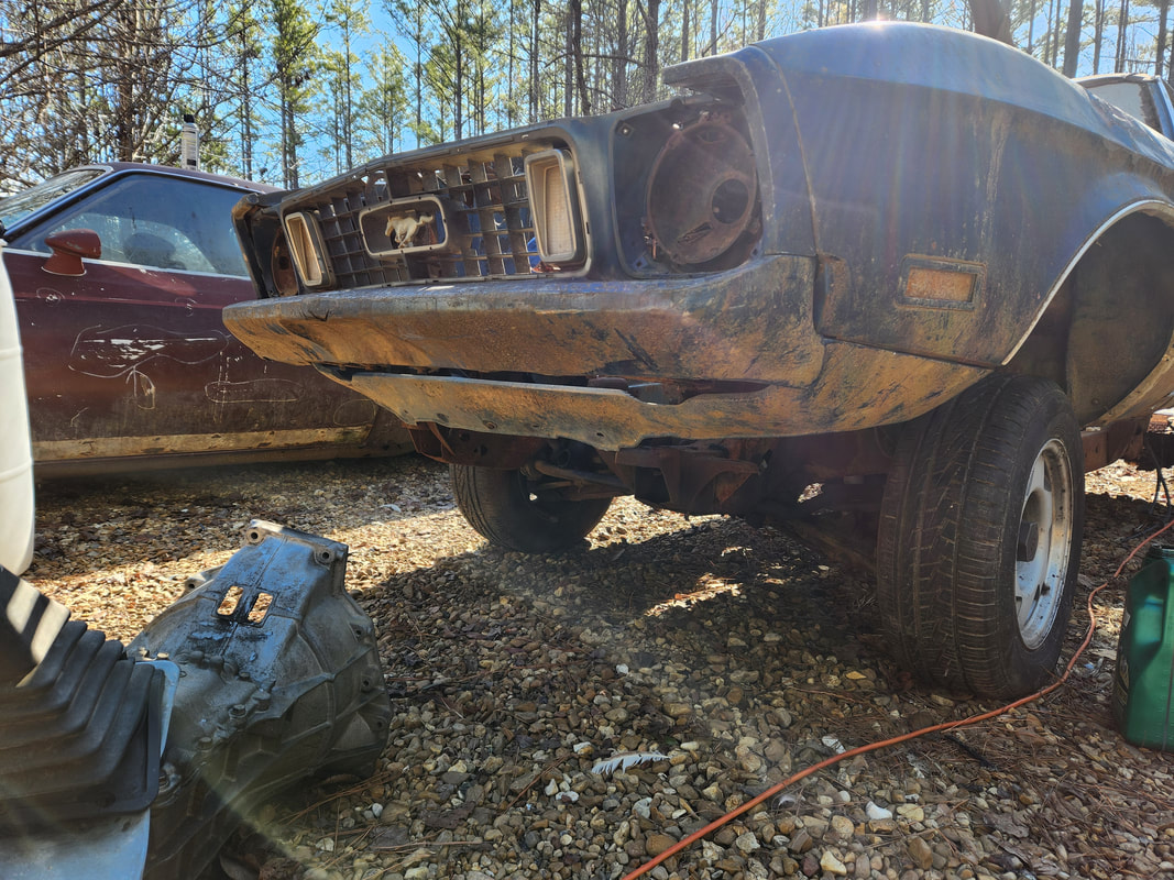 The valance panel which is still pretty intact is mounted in place, secured to both fenders with the stock bolts and retainers. The next thing to install is the hood. This was simple, except for the idea that the hood is huge and bulky as a result. All I needed to do was get a prop board in place to hold the hood then carefully position the hood to get one bolt started. Once that was done I jumped to the other side to get another bolt in then back to the other side and then again until all four bolts were in place. I lowered the hood and readjusted the bolts so the hood would close as close to even with the fenders as possible. Since all these body panels have been dented or otherwise beaten on to some degree, I couldn't expect everything to line up perfectly. 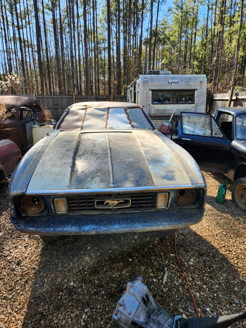 The hood is installed on the hinges and aligned to allow it to close evenly with the fenders on either side. 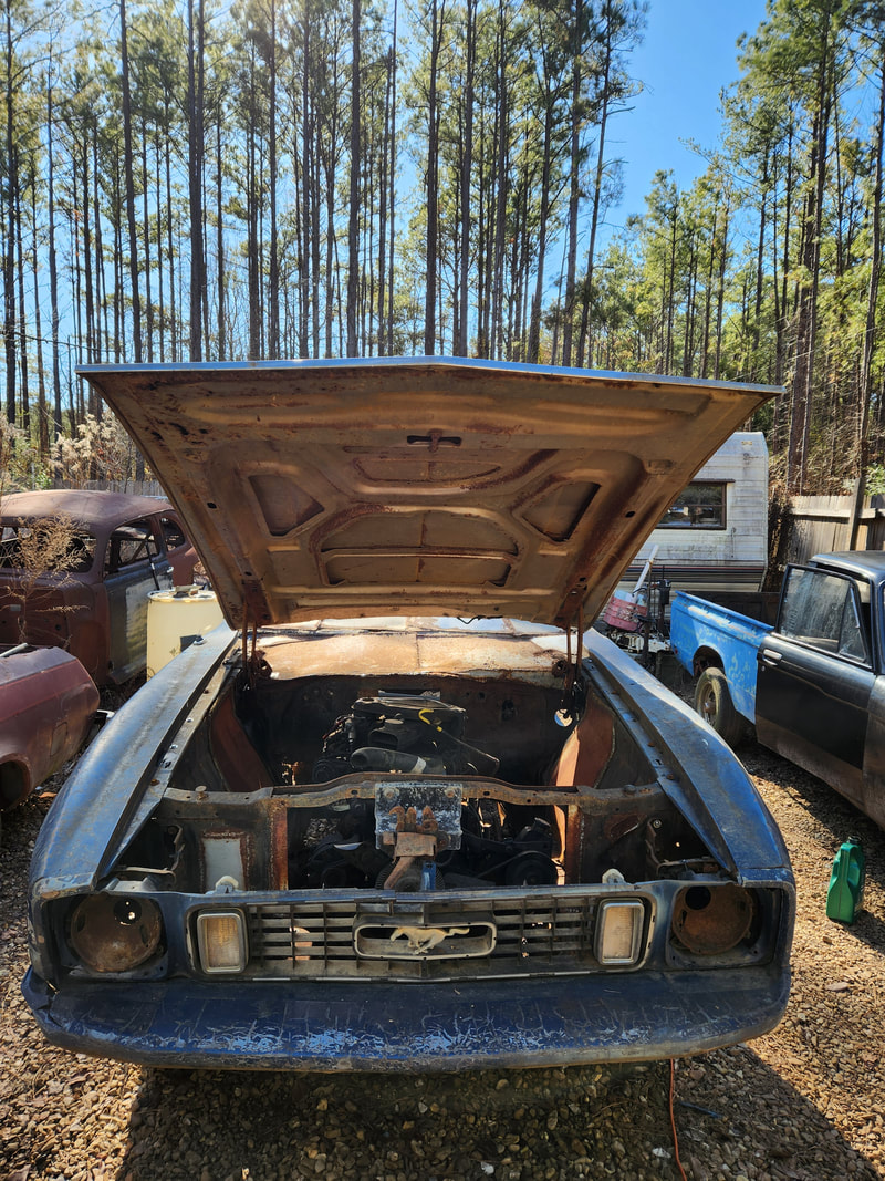 The hinges were oiled up to allow for opening and closing without damaging the hinges. At least the engine is now protected from the elements. The last thing that had to be addressed on the car was the installation of the doors. This was easy too, except for the idea that the doors are heavy. I had to cut off the welded on frames that I had on the doors when the car was a chicken coop. Those frames held chicken wire on one door and sheet metal with a fan on the other door. With the conduit frames cut off I ground the remaining weld metal as flush as possible then stacked two crates to use for holding the doors to allow me to put the bolts in. I had to oil the bolts to allow for the bolts to cut into the threads on the doors ahead of time so when I put the bolts back in now they would go in easy. 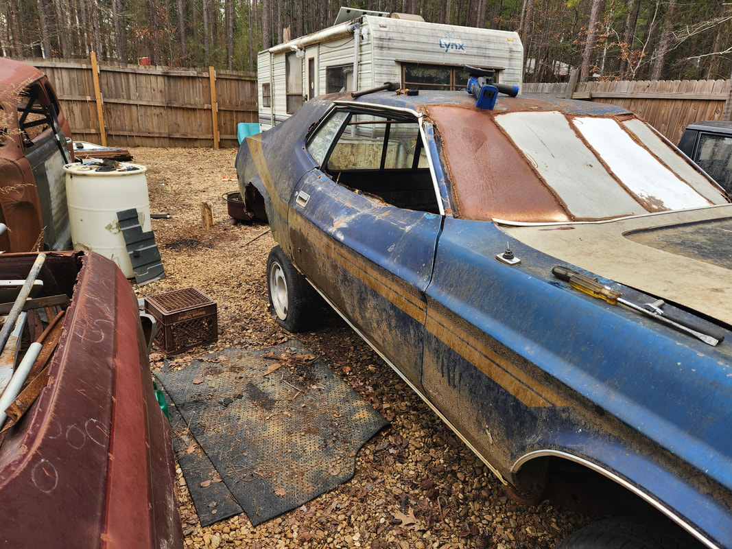 The right door is installed and aligned so it can open and close without binding on the back of the fender. 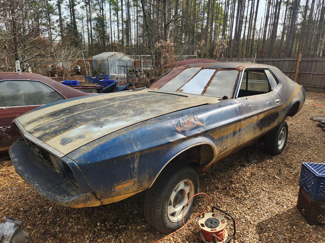 The driver's door is installed and aligned to ensure proper opening and closing wiu 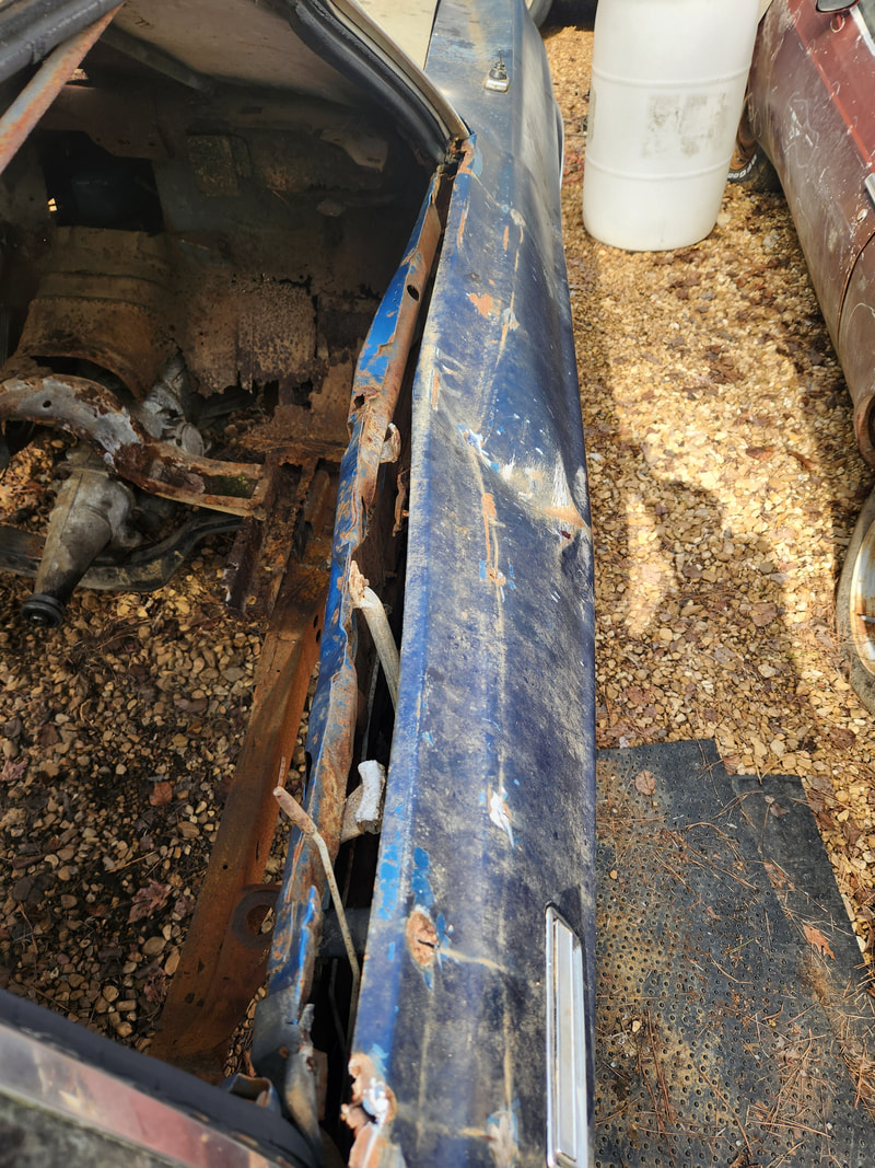 Because the passenger door suffered a serious tree impact which also collapsed the same side of the roof at the A-pillar, this door may either need some serious reconstructive surgery to allow for installation and operation of a stock window, or do the same kind of thing like with the 51 Chevy where a piece of plexiglass is installed or worst case, just replacing the whole door shell. We will have to see when we get to that portion of the project later on. With the doors on, that concludes the assembly of the body on the car. The next area to take care of will be the inside since there is no floor whatsoever. I will have to weld in some type of framework to hold the sheet metal that will make up the floor. I will also have to assemble some kind of transmission/driveshaft hump/tunnel since the transmission is still high enough to require clearance in the middle. Also the support will be necessary to ensure that the seats will be solidly mounted and hold me and a passenger securely, especially when the car is in motion. There is a section of the floor at the front where it starts angling up to the firewall that will need heavy patching since its rusted out heavily. After patching the rust holes at the tops of the wiper cowl I was able to start getting the fenders on. This was rather simple for all intents since it only involved adding a few bolts along the tops of the fenders and a couple at the rear in the area where the door meets the back of the fender. I had to apply oil o the bolts to help in recutting the threads so the screws don't cross thread and damage the threads on the retainers on the side panels.  The left fender is bolted up, using most of the stock bolts along the top to hold the unit in place and at the rear of the body.  On the right side I had to use some nuts and bolts along the top since the retainers were missing.  At the very bottom of the rear portion of the fender I ended up having to drill a couple holes through the panel and into the body to add sheet metal screws to hold the panel since the mounting tabs for these fenders were rusted away.  On the right side I was also able to add the trim panel along the rocker panel to cover up the junctions where the rear of the fender meet the front of the rocker panel. Even this panel needed a hole and sheet metal screw to secure. With the fenders bolted up and for all intents aligned where I believe where they need to be, I moved on to adding the grille. This component is bad in the sense that the tabs where the retaining bolts go are all broken on both sides. The only point where I was able to use the stock mounting points was in the middle where the hood latch support is located. For the sides where the headlight buckets are I ended up drilling small holes through the top and bottom to apply some wood screws that were able to cut into the plastic skin of the bumper cover where the grille sits over. 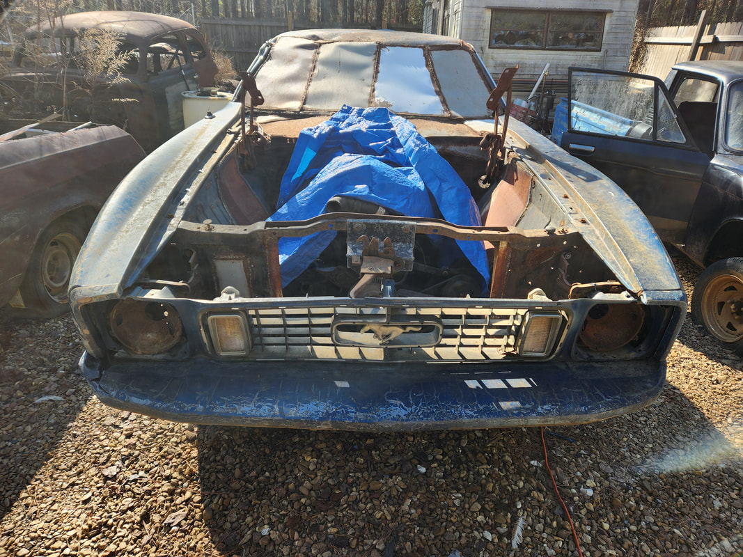 The grille panel is mounted in place at the front.  A closeup of the headlight bucket showing the screws at the top and bottom in the grille body that were applied to hold the panel in place. The first screw is at the upper left just above the headlight trim screw hole and the other is on the lower right just to the left of that mounting hole for the trim.  The left side of the grille got the same treatment with a couple holes drilled in place for wood screws that are holding the panel to the plastic skin of the bumper cover and a portion of the fender around the headlight bucket.  Closeup showing the one screw going through the top of the fender metal and the top of the grille plastic to hold the grille in place. I also had to drill a couple holes to install a zip tie where the plastic was broken to hold the plastic together around the top of the headlight bucket so that part of the grille body isn't flopping around. On the other drivers side I was able to get one hole drilled and a screw in place but I had to use a zip tie to hold a broken portion around the top of headlight bucket. With the grille fully secured I added the bolts to hold the center of the grille to the latch assembly. With that, the next session will be the addition of the valance panel and the hood, which will require possible realignment of the fenders to ensure that the valance panel and hood align with those two panels. From there I can bolt the doors up to finish up the assembly of the body. Now that the long work is done on the tailgate, I can start looking at getting the rest of the body assembled on Truckstang 2. Before I can install the fenders I have to patch two sides at the tops of the firewall/side wall area which are apparently prone to rust as these points collect water enough to rot the metal. As was always the case, I ended up having to weld several pieces of sheet metal over the open spots, closing the area up. These areas don't have to look pretty, they just have to be functional, since the fenders will be covering these areas anyway. 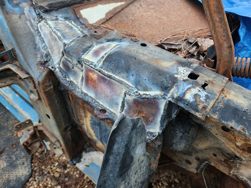 The right side opening wasn't as bad and was able to be closed up a little bit easier than the left side. 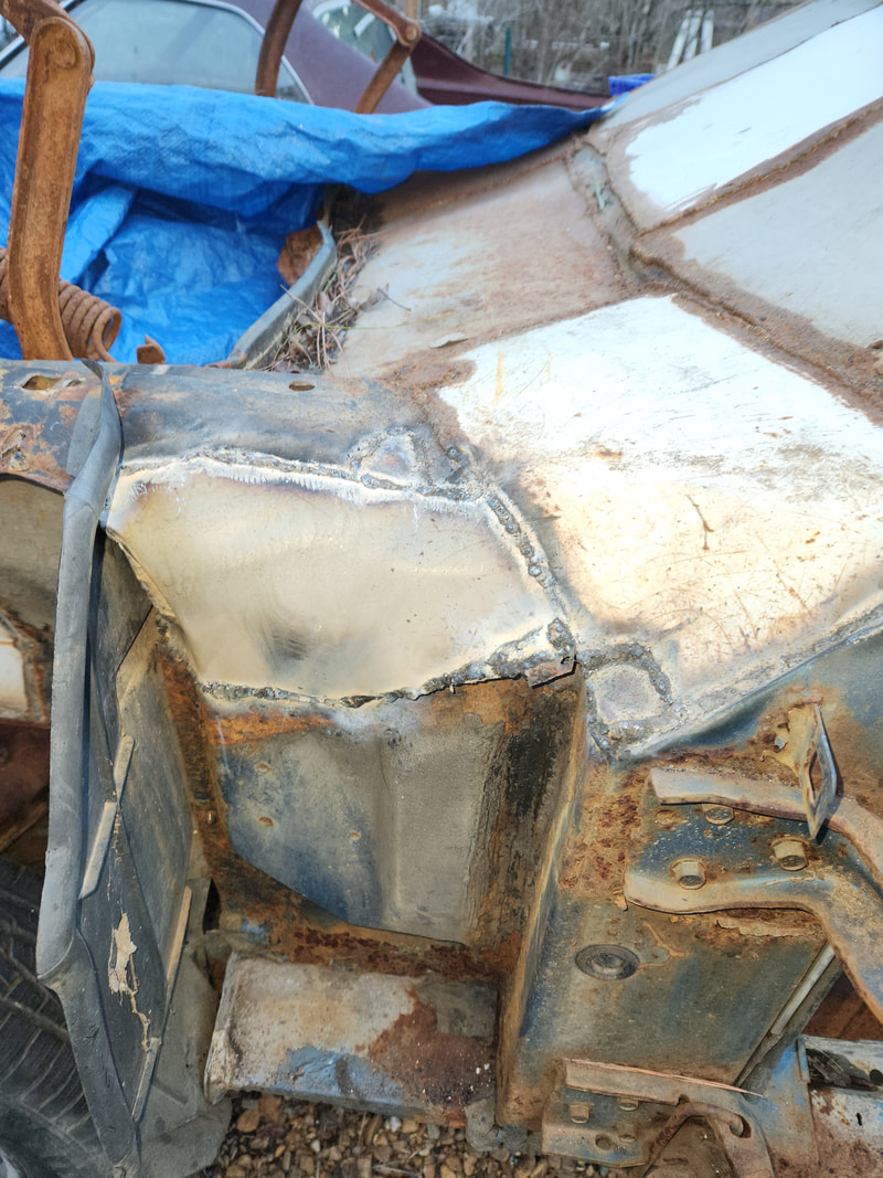 The left side was a little messier but not too bad, still accomplished the goal of closing up the giant rust hole in the inner body member. 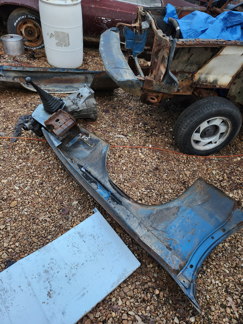 The left fender has its giant dent hammered out to straighten the panel as best as I could prior to installation. Now that the rusted open areas have been welded up, I can move forward with the installation of the body panels. I took a moment to knock out the large dent that was present in the left fender from when the tree fell on the car. It isn't pretty but its a lot better than the huge dent that was there. Maybe later on if I really care I can mud up the area to smooth things out, if I don't just replace the fender all together. With the latch assembly fully functional on the tailgate, the last move is making the cap out of the piece of trunk lid I cut off so I can cover the top of the tailgate to make the whole thing follow the same lines as the original Mustang rear end. this piece of sheet metal would have to be able to be removed while still fitting in such a way as to look like it belongs. The first thing I came up with was welding some more long bolts to the inside of the panel then drilling holes through the tailgate body and the sheet metal skin where the bolts would pass through, allowing the trunk lid piece to fit like a modular piece of the overall tailgate. 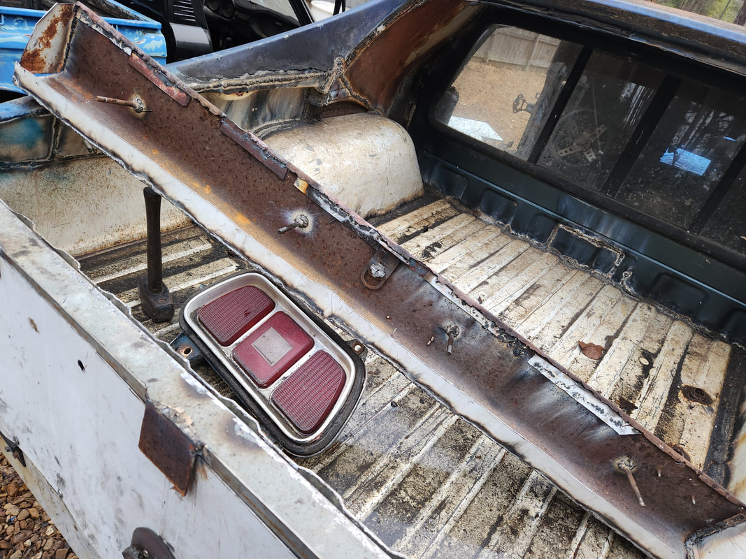 Four long bolts are welded to the inside of the trunk lid as a means of holding the panel in place without being visible from the outside. Note some of the holes drilled through the sheet metal panel and through the tailgate. With the bolts welded in and the holes drilled, I was able to secure the trunk lid to the top of the tailgate. The next move was to weld on a long narrow piece of sheet metal to the inside of the trunk lid to cover the opening that was present between the top of the tailgate and the bottom of the trunk lid. After welding the piece of sheet metal to the inside of the trunk lid, I then drilled holes along the bottom of that piece of sheet metal and into the top of the tailgate so that part of the trunk lid assembly can be secured with sheet metal screws. 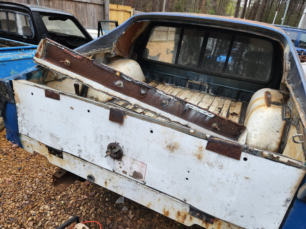 A long narrow piece of sheet metal is welded to the inside of the trunk lid and has holes drilled through it and the top of the tailgate to allow the inside of the trunk lid to be secured with sheet metal screws. Also note the sheet metal caps that are welded to the sides/ends of the trunk lid. Lastly I cut a couple small pieces of sheet metal to serve as caps for either side of the trunk lid. These pieces were welded in place, covering the small dead spaces between the trunk lid and the top of the tailgate body. With careful manipulating, the trunk lid piece can be removed or installed without much hassle. The holes for the large bolts are bigger than the bolts on the trunk lid so there is room for play when removing or installing the panel. 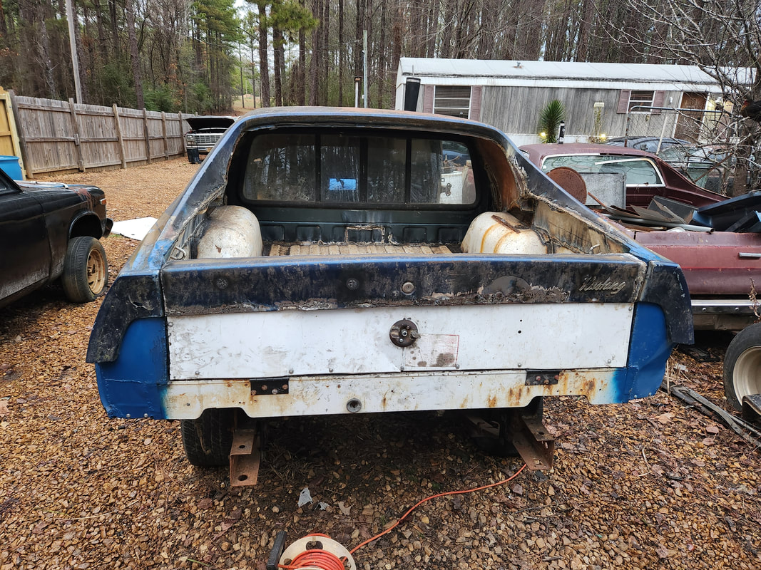 The trunk lid piece is fully secured to the top of the tailgate with all fasteners and lined up properly so the lock face lines up with the latch knob on the tailgate. We even managed to keep the Mustang logo on the right side of the trunk lid. With the tailgate all done, I can look at applying spray paint to help protect the metal, especially the welds. The next main thing when it comes to the tailgate and rear end will be figuring out how to do the taillights. I still have a complete taillight assembly, which I can't use based on how the tailgate is made. My plan will be to chop the outer third of the taillight lens and bezel and attach it to the outer portion of the rear then attach the other 2/3 of the lens/bezel to the end of the tailgate on either side. I'll use COB LED panels that would be glued inside the lenses and wired as needed to make the lenses light up as the old taillights would've. This way the rear of the Truckstang will still appear like the original 73 Mustang while still having the functional tailgate. With the section of the S10 bed trimmed down to fit as a tailgate, the real meat and potatoes of the project begins. I had to assemble a solid tailgate that also has a means of latching the thing without looking too tacky. I could easily just use simple sliding door latches like I did on the 51 Chevy doors, but unlike the temporary nature of the 51 Chevy's doors, this will be a more permanent setup. The first thing I had to do was begin to close in the sides of the tailgate panel and come up with a latch. 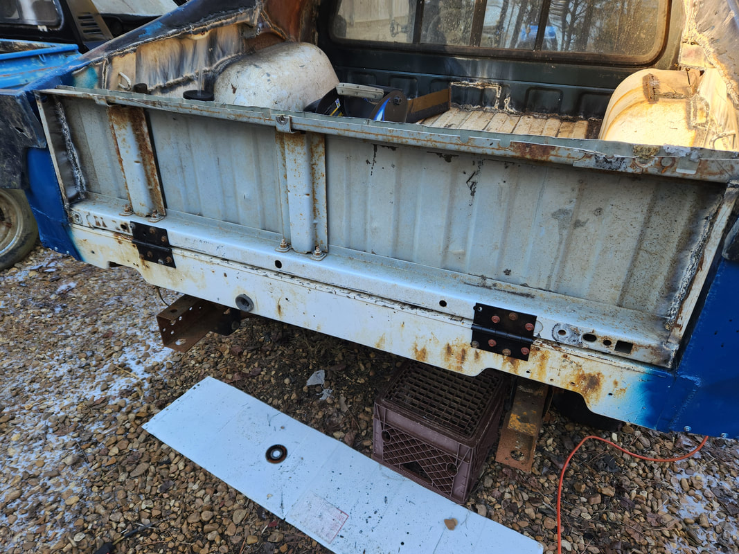 Heavy duty hinges are used, secured with self tapping hex head screws to hold them in place on the bottom of the tailgate as well as the rear of the bed. 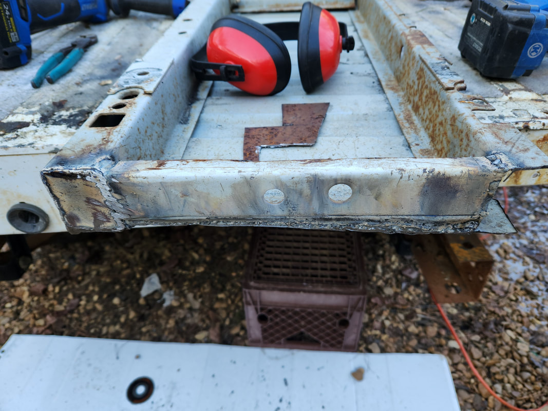 To close in the sides of the tailgate, salvaged pieces of bed support metal is welded to serve as sides for the tailgate body. The idea I came up with for the latch is simple and mimics that of a regular tailgate. The center of the latch is lever made from a piece of flat steel with a center hub allowing the piece to be mounted on a bolt welded to the inside body of the tailgate to serve as a fulcrum The metal piece will rotate on the bolt but only a few degrees in either direction. The metal piece also has a couple bolts welded to either end to serve as studs to hold the rods I will fabricate from more scrap. The rods are made from conduit with a long bolt welded in one end and an eyebolt welded in the other. The eyebolts attach to those stud bolts on the lever while the long bolts will extend out through the sides of the tailgate body. Holes drilled through the sides along with holes drilled through the sides of the bed corners allow the long bolts to pass through to serve as latching rods to hold the tailgate in place. To allow the rods to stay in place, short pieces of conduit are welded over the holes to serve as guides to allow the rods to pull in to clear the sides of the tailgate body while passing through to latch the tailgate as intended. 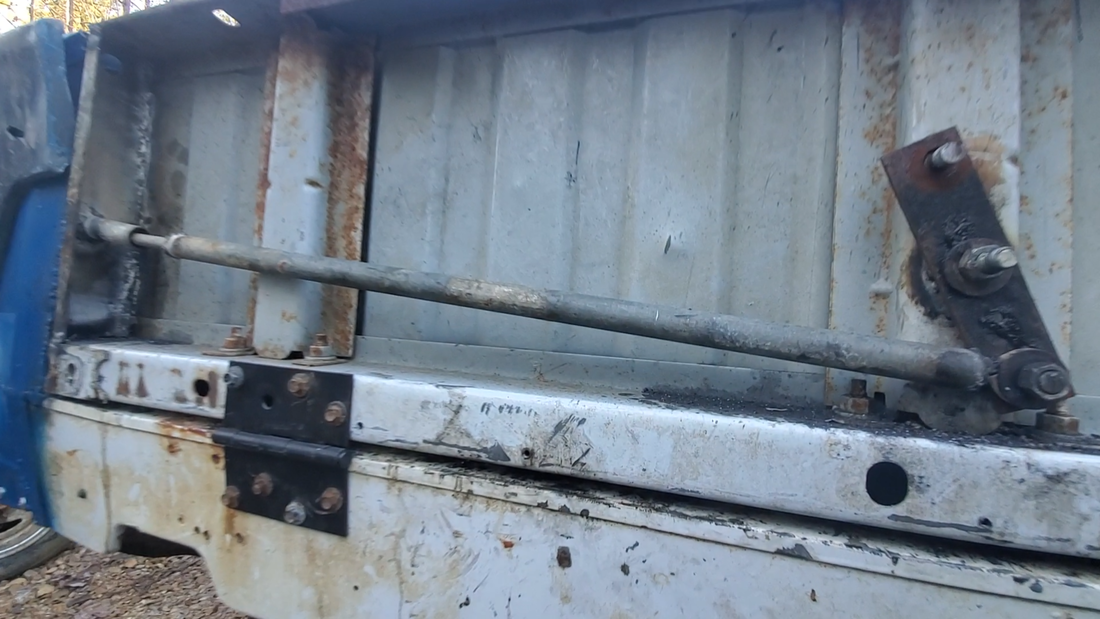 The left half of the lever/latch assembly showing the conduit that's welded on the side of the tailgate along with the rod that is secured to the lever and passing through the conduit to the side. 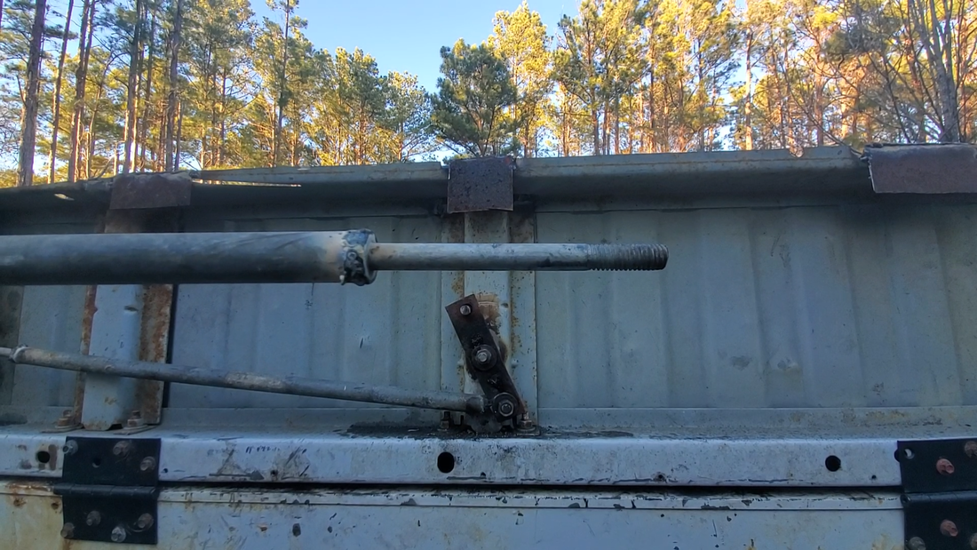 The other end of the rod showing the long bolt welded to the end that serves as the latch for the tailgate. I ground the threads on the bolt to help smooth things to allow the rod to pass through the tailgate and bed holes a little smoother. 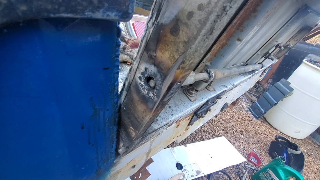 The side of the tailgate showing the hole drilled through the side where the rod passes through to the bed to help latch the tailgate. 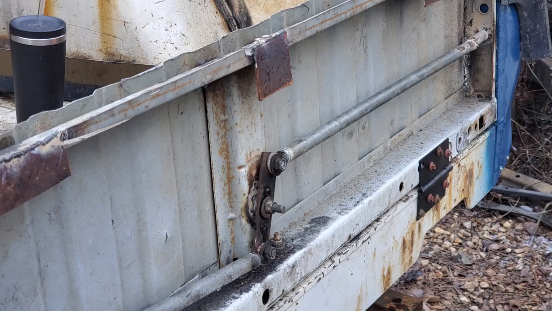 The other rod is attached to the lever and inserted trough the conduit on the side of the tailgate. To rotate the lever/rod assembly, I used a truck body bushing cap as a knob. i welded tabs of small pieces of metal to opposite sides of the hub hole to serve as levers to grip to rotate the knob. I also drilled two small holes next to the hub hole and after lining the knob up with the rotating lever, drilled the holes through that piece as well. I tapped the holes on the lever to accommodate 10-32 screws that will hold the knob onto the lever to allow the thing to be rotated. Lastly I cut a large piece of sheet metal to serve as the skin for the tailgate. I lined things up and cut a large hole over where the lever is located to allow for the knob to be installed and freely rotate without restriction.  The knob made from a bushing cap with metal tabs welded on as gripping points to rotate the knob. Extra holes are drilled to the sides of the center hole to apply smaller screws to hold the knob to the lever inside the tailgate. 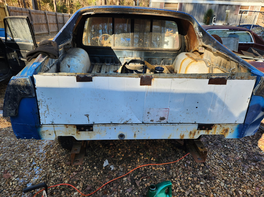 A large piece of sheet metal is cut to serve as a skin for the tailgate. Three metal tabs are welded along the top of the tailgate to serve as catches to hold the top of the panel in place while sheet metal screws hold the sides and bottom of the panel to the sides of the tailgate. 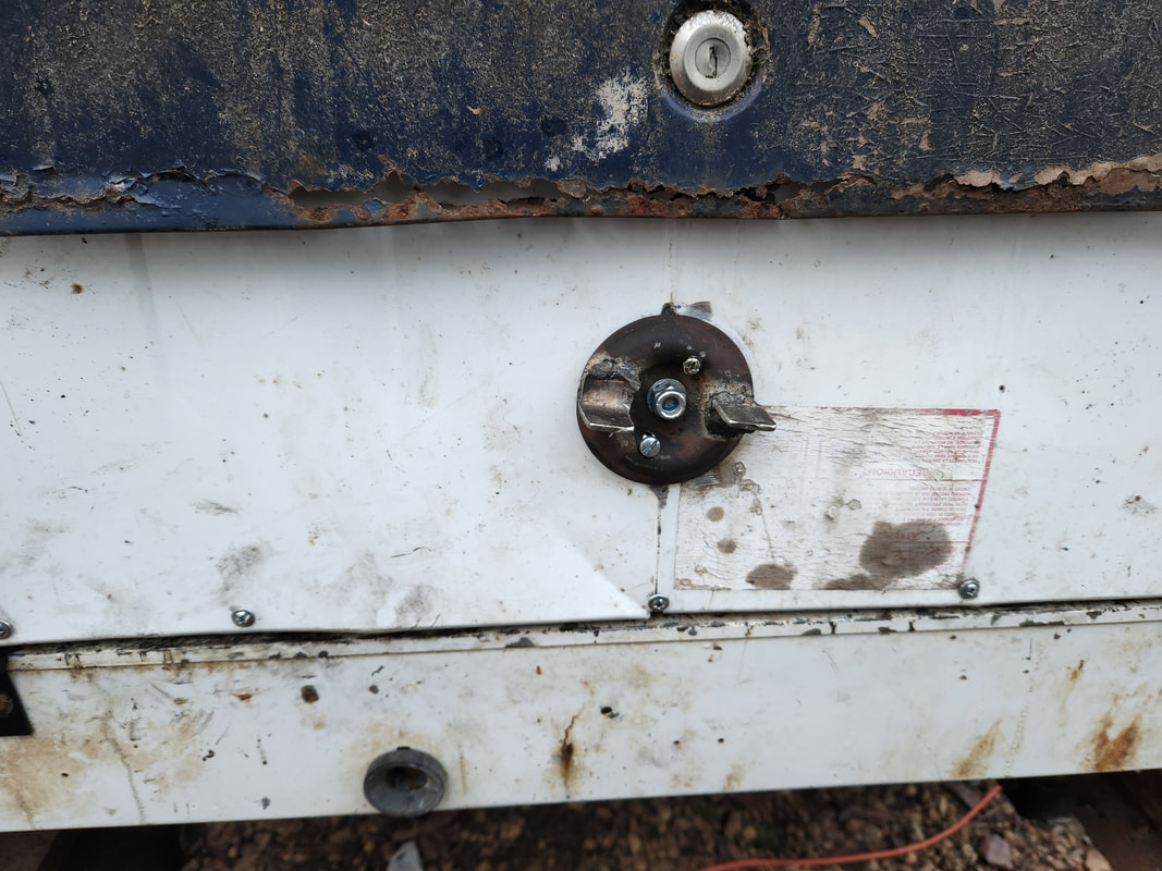 After cutting a large hole in the panel to expose the latch lever, the knob is screwed to said lever, covering the large hole while still allowing the latch to function as designed. With the latching assembly all done and tested working I was able to install the sheet metal panel in its entirety, using sheet metal screws secured after drilling holes around the edges of the tailgate to hold the panel in place. Once the panel was on, I secured the knob with the two 10-32 screws, using loc-tite (as I did with the nuts on the lever studs/nuts). With all that metal secured, I did a test fit to see how my trunk lid piece fit so I can move on to that part of the tailgate next. With the addition of the two sheet metal panels on the ends of the quarter panel corners, I moved on to making access panels for the bottom area at the rear of the quarter panels. These areas were rusted out and the quarter extensions still need to be able to be installed and removed for any given reason. Since the bolts go in from the inside of the quarter panels, the access panels would have to be installed using screws versus being welded in place as permanent parts of the rear quarter panels.  The access panel for the left side fabricated from a piece of scrap sheet metal, with side tabs to help the panel fit better in the opening that needs to be covered. 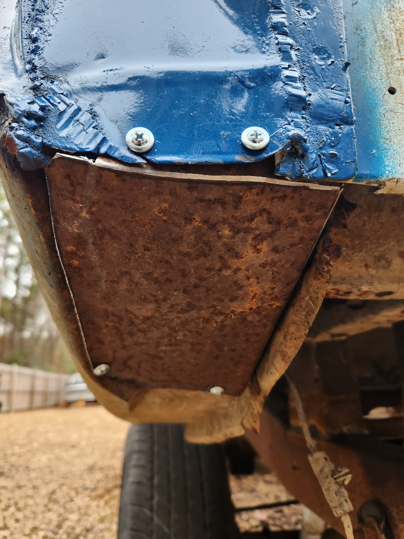 The access panel is installed with sheet metal screws, trying to take care to keep the appearance as clean as possible. I eyeballed and lined up a piece of sheet metal to fit into the open space, adding tabs to the piece of sheet metal that would be folded up in the placement of the panel. Once the panel was manipulated and shaped to fit as best as possible, I drilled four holes through the access panel and the quarter panel and the sheet metal rear panel in order to add sheet metal screws to hold the panel in place. Of course I had to install the quarter extension before permanently installing the panel so once that was done, the panel is in and I can go ahead and spray paint the piece later on to help protect it from rusting. 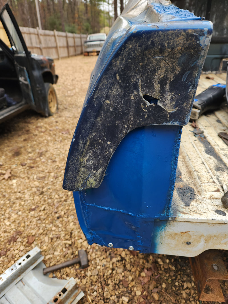 The quarter extension piece is installed, along with the access panel. The area is painted up to help protect the welds and bare metal areas from future rust. On the right side I had to do a little more. Since the bottom of the quarter panel is rusted badly, I had to cut a piece of sheet metal and weld it from the inside over the rusty area to create a crude patch, same as I did on Truckstang to patch the holes on those quarter panels. Once that was all done, I was able to create the access panel that would fit. The screws went in the same spots on the right side as the left side except for the one on the left side that was more to the side at the front compared to the two on the right side that are on the direct front end of the panel. With the quarter extension on and the access panel on, I started looking at our future tailgate. 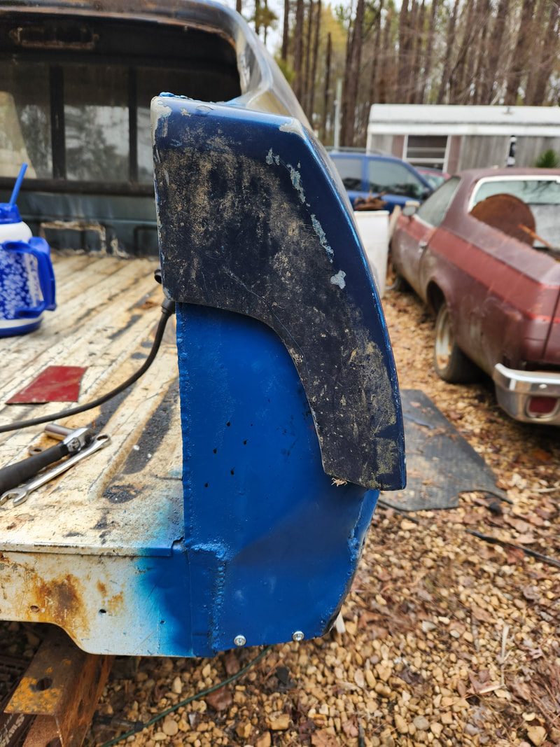 The quarter extension is installed on the right side to allow for the installation of the access panel, which is already in place in this pic. 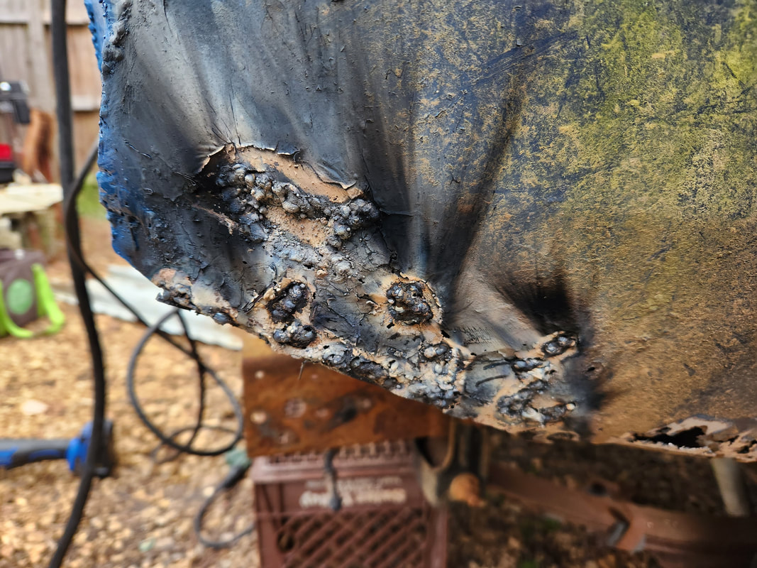 As an added bonus I had to weld in a patch of sheet metal from the inside of the lower quarter panel. The popcorn welds may look awful but after grinding the bulk of the slag down I can later on apply body filler to smooth out this section of the body. 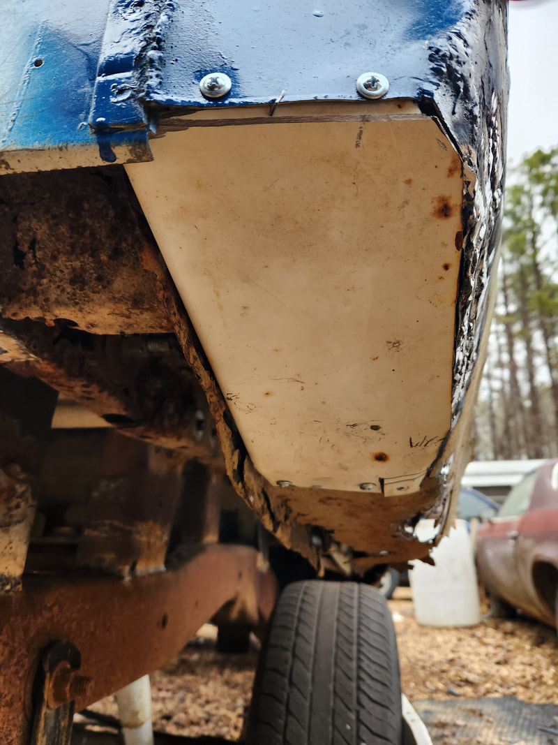 The access panel is installed on the bottom right side under quarter panel. When I was initially prepping the S10 bed for the car I chopped off the front portion of the bed, about 20 inches of panel give or take. I decided to use this odd piece of panel to make my tailgate since it was nice and sturdy with a couple of support pieces stretching across the panel. I would situate the panel with the pickup bed floor on the inside and the other portion on the outside. Later on I will install a large piece of sheet metal across the member to create the outer portion of the tailgate that would help create the straight lines across the rear of the car. The biggest portion of the tailgate will be the installation of the rear most lip of the old trunk lid, which will be welded to the top of the tailgate/bed panel so when the tailgate is in place, that trunk lid lip will be even with the quarter extensions on either side. This would go a long way towards making the rear of the car still appear original while still having a functional tailgate. 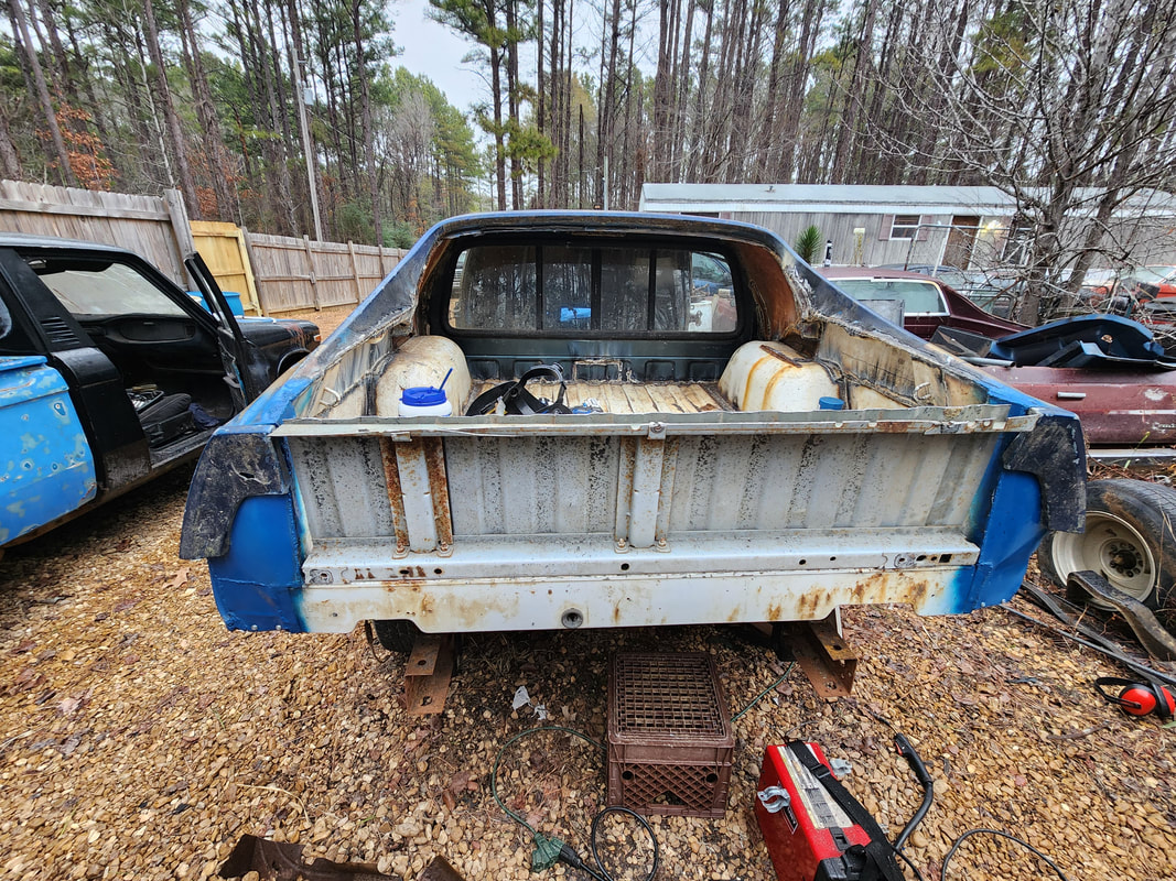 This cut off section of the old S10 bed is trimmed down along the portion that will be the top in order to use it as a tailgate. The top isn't even due to the fact that the left quarter panel is slightly lower after the tree clobbered the left quarter back in 2020.  The uneven cut of the tailgate panel will be covered up when this lip of the old trunk lid is welded in place across the top of the panel. Of course the rest of the trunk lid is scrap metal. I do have some unique plans for the tailgate. I do plan on fabricating a form of latch for the thing that will incorporate using some rods that will pull in from either side and insert into the corner sections of the bed to hold the tailgate in place. I plan to fabricate a cam of sorts that will sit in the middle of the tailgate, rotating to pull the rods in from either side to allow for the opening of the tailgate. When the sheet metal panel is installed, I plan to look at using the old Mustang gas cap as the rotating knob/wheel to rotate the cam to pull the rods in to open the tailgate. This way the rear of the car will definitely appear to be original, even with the old gas cap, which will actually serve as the tailgate release. Once that's done I will go on a tangent for a quick moment to look at the taillight situation to see how I can make that happen and keep the originality of the mustang rear. The bigger portion will be me moving to the front of the car, getting some areas welded up so I can start installing the rest of the panels on the car so I can wrap up the body work portion of this build. |
