|
The first version of the seat mount setup that I done was hardly successful in the sense that it made the seat sit extra high in the cab of the car. The mounts, being from a minivan with a high ceiling, had our VW seat sitting too high, barely able to fit in the car. I wouldn't have been able to fit as my head would've been through the ceiling. The next move was to modify the minivan seat mount. This involved cutting the two sides of the minivan mount horizontally, trim out the middle section then reweld the two halves together, making the sides a few inches lower. 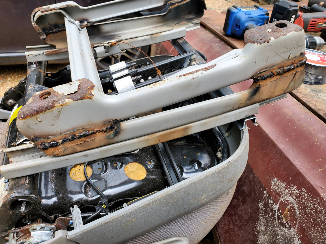 The minivan seat frame after cutting it in half, removing the center section then rewelding the two halves back together to make an overall shorter frame. 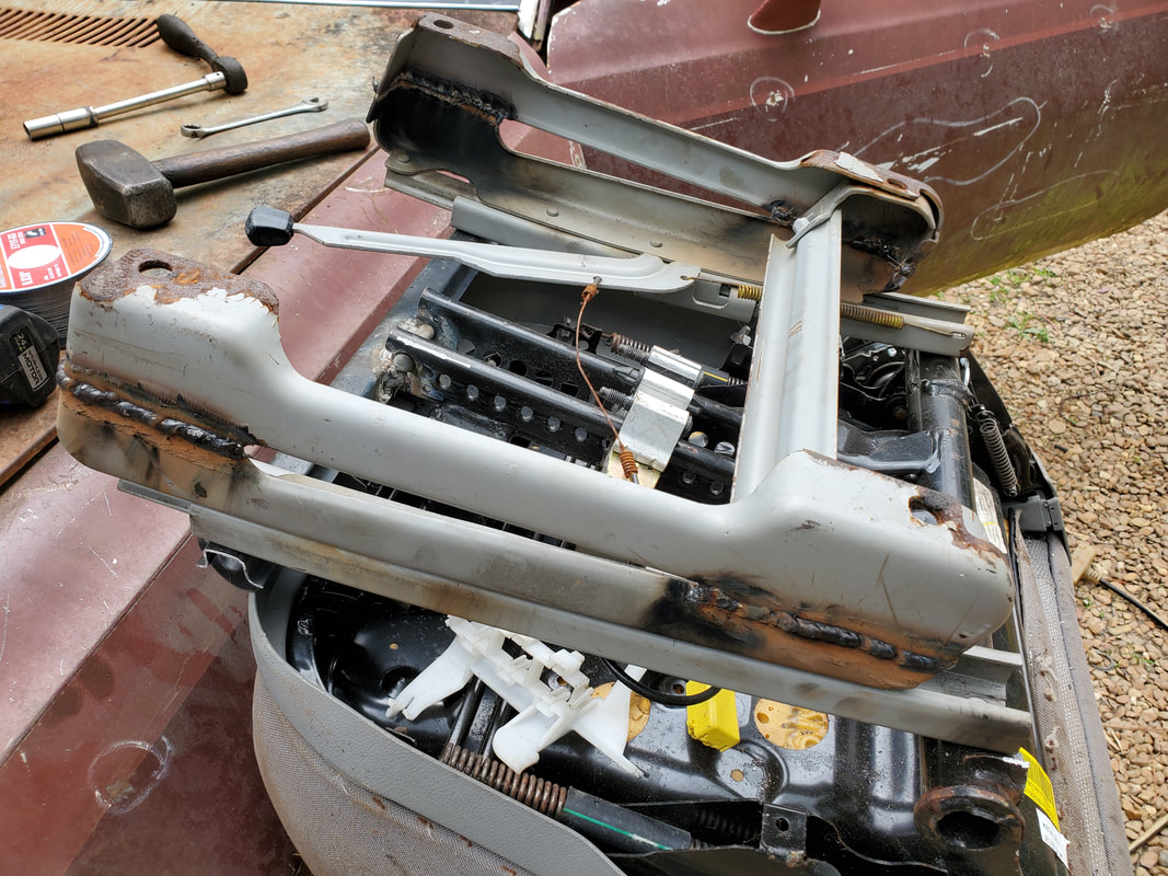 Another angle to the frame after it was cut and rewelded. After doing the mount in this new configuration I tried to fit the seat once again. And as before, the seat still sat too high. It wasn't near as bad as before but still bad. My head was touching the ceiling and that was even after reclining the seat to accommodate the "low" ceiling. I still had some more work to do on this improvised seat mount. What I ended up deciding this time is to cut the sides apart once again and this time, sandwich the two pieces together, side by side, and reweld that together. This would also involve me having to cut the linking bar between the two sides and shortening it a little then rewelding that just as well. 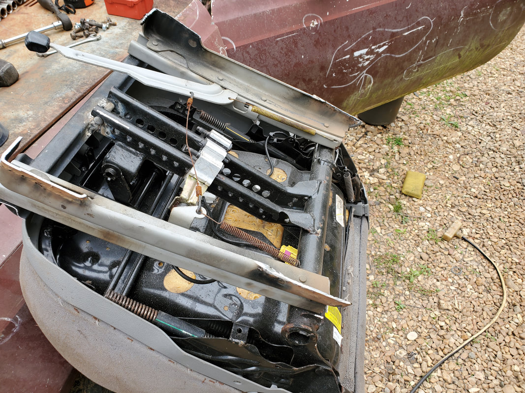 Cutting one the one half of the frame back off and removing the welds prior to sandwiching the two pieces together. 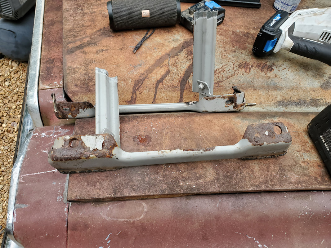 The two halves after cutting them free again. The center bar will need to be shortened to accommodate the narrower spacing between the two frame pieces. I tacked the two halves together as a test fit so I could try to fit the seat once again. I bolted the two sides back to their respective points on the T of the VW seat. With the new sandwiched together seat frame situated I again tried to test fit the seat. Obviously, it was better than before, but still not quite right. My head was still dangerously close to the ceiling, enough so that if I hit a bump, my head would hit the ceiling for sure. I had to figure out some kind of alternative to this madness. 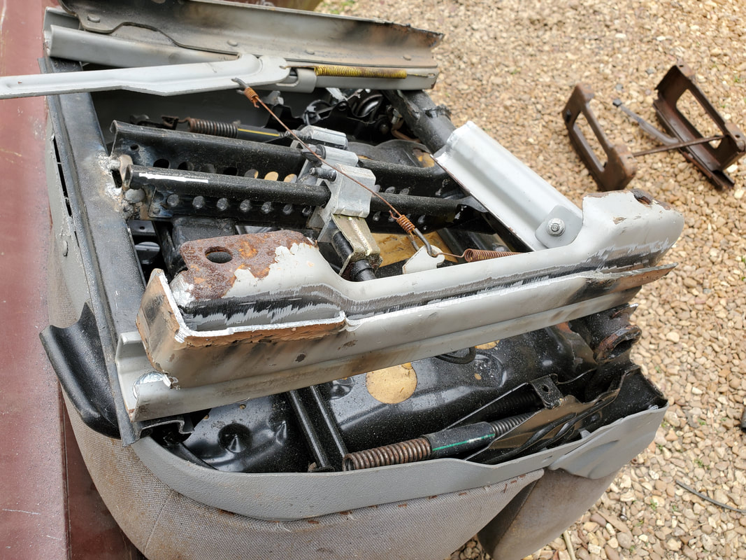 The two halves sandwiched together side by side prior to adding some light welds. My final alternative was to cut into the T of the VW seat. I had to remove the plastic molding at the front of the seat and the old seat slide mechanism from the VW seat I then cut a couple notches into the arms where I initially had the rear of the frame mounted at. I cut 2/3 the way into the tube and removed that metal so I still had the bottom portion of the tube left with the mounting hole for the rear of the minivan frame rails. I used some shorter bolts to hold the rear of the minivan frame rails into the notched portion of the tubes then mounted the front points of the frame rails in place. I operated the mechanism on the seat that raises or lowers the seat base, lowering the seat as much as possible. After a test fit, I found that the fitment wasn't that bad. My head had 3-4" of clearance from the ceiling, even before reclining the seat and my knees didn't hit the bottom of the steering wheel, even in a lowered position. I might be pretty good now with this configuration of the seat frame. 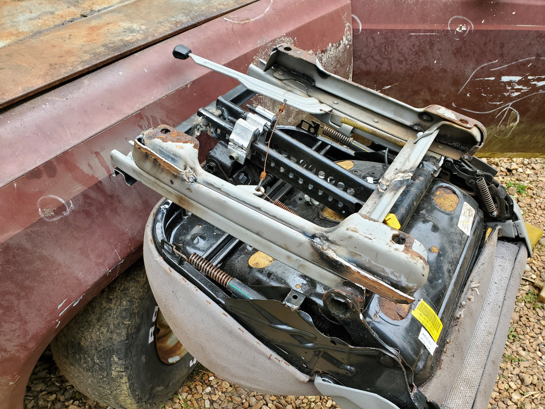 The two halves tack welded together and fitted into notches cut into the arms of the T at the back of the VW seat. 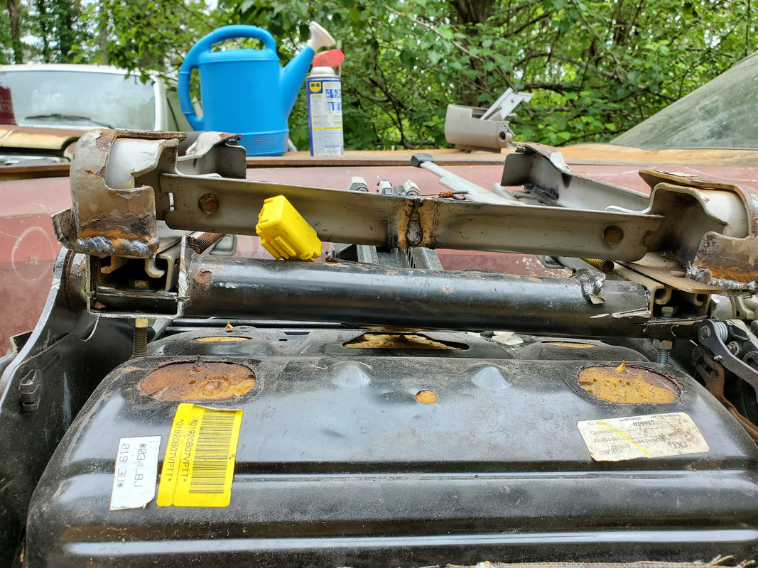 A straight on view showing the notches cut into the arms of the T and the seat frame rails resting in the notches and bolted in place. 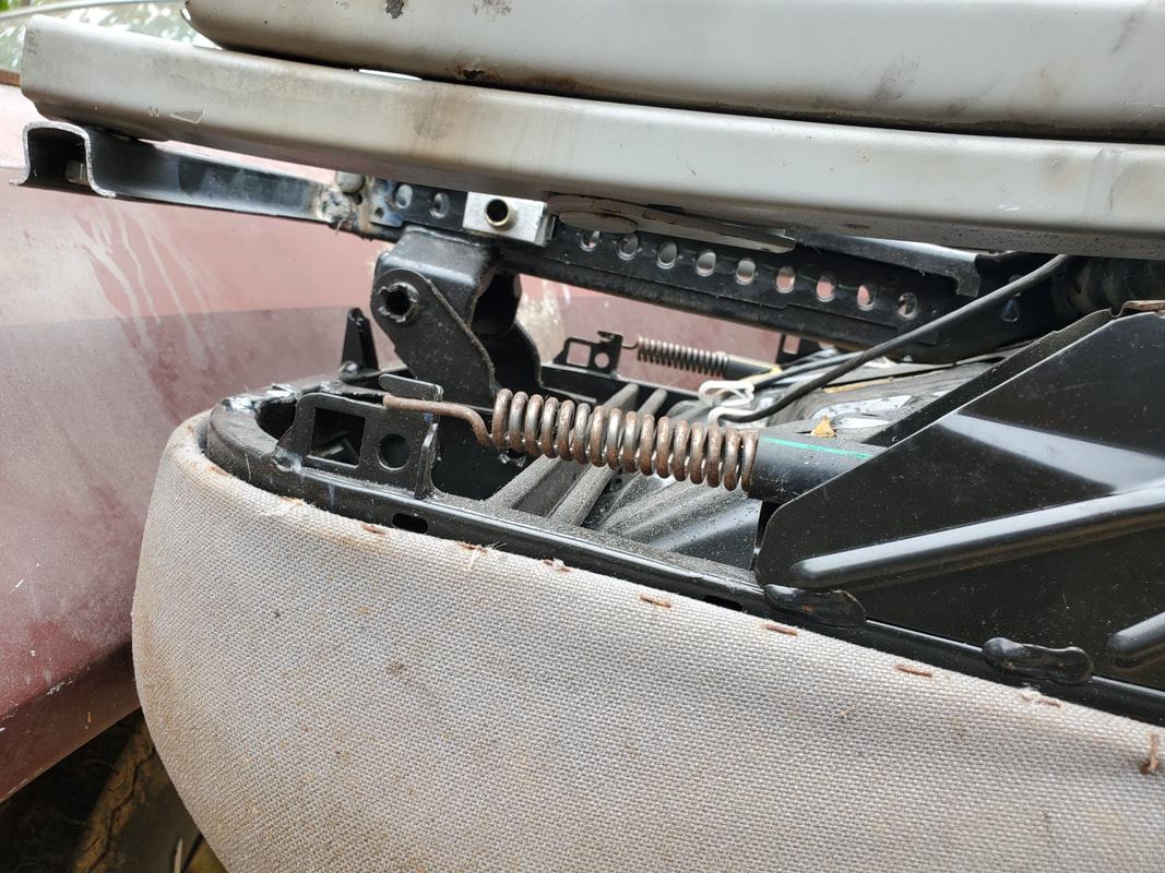 Front of the seat after removing the plastic molding and removing the old seat slider lever. 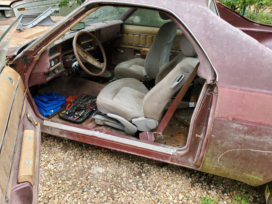 Seat sitting in the car after test fitting. Welds still need to be added to fully strengthen the frame and the frame needs to be bolted to the floor in the car to complete the job. With the seat finally cleared as good, I have to finish welding the two sandwiched pieces on both sides together, maybe even weld the rear portions of the frame rail to the notches in the tubes. Once that's all finished up, I just have to drill holes in the floor to mount the seat once and for all. Of course, I'll have to make the same modifications to the other seat frame and seat so I can duplicate this same setup on the passenger seat. Once that's all taken care of, I can finally clear this shitshow dealing with getting seats in the car. Of course, its better than spending $300+ for a set of aftermarket racing seats but its without its headaches. This of course is a day in the life of a DIY improvising workshop.
0 Comments
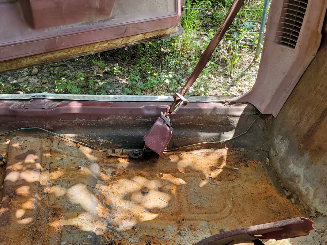
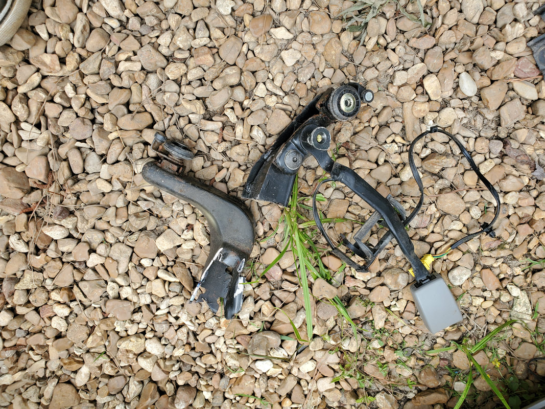
When I left off with the seatbelt reassembly, I had to figure out a way to attach the lower reel assemblies to the floor. Before I went to any extreme on the improvisation, I tried to pull the bolts out one last time. I put a breaker bar on the star bit and wet things down with WD40. With a tug I got both bolts out all the way, with no damage to the threads. With that I was able to reattach the lower reels from the driver's side reel to the floor. I still had to fix the broken tab on the passenger side reel.
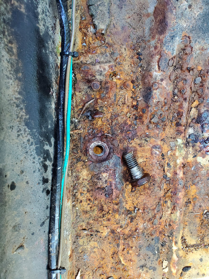
Bolt from floor mount after removal, everything looked pretty good.
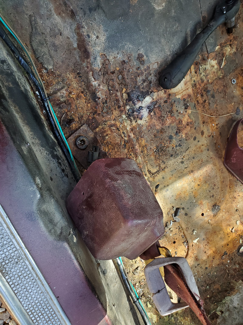
Driver's side lower buckle mounted to floor.
To remedy this problem I took a large washer, probably 5/8" or 3/4" hub, and welded it at an angle to the stub of the tab. The washer is thick enough that it is similar in strength to the original material of the reel's mount. Duplicating the angle from the driver's side reel, I managed to get the washer in place so I can bolt down the passenger side reel just as well. With that little bit of business out of the way, I can now turn my attention to the seats. 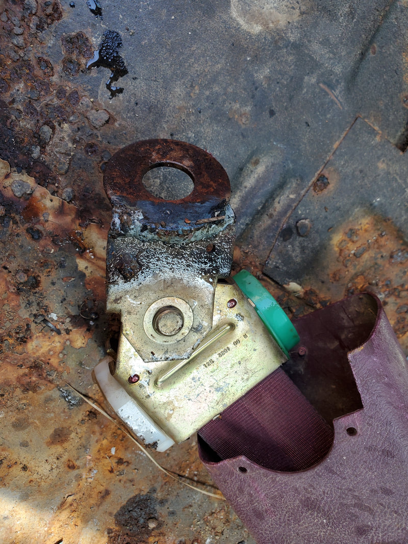
The washer that was welded on to the tab to recreate the mounting tab for the lower reel.
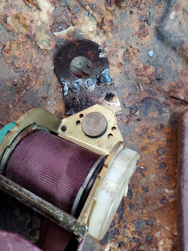
Another angle to the welded on washer.
Lower reel bolted down to the floor mount.
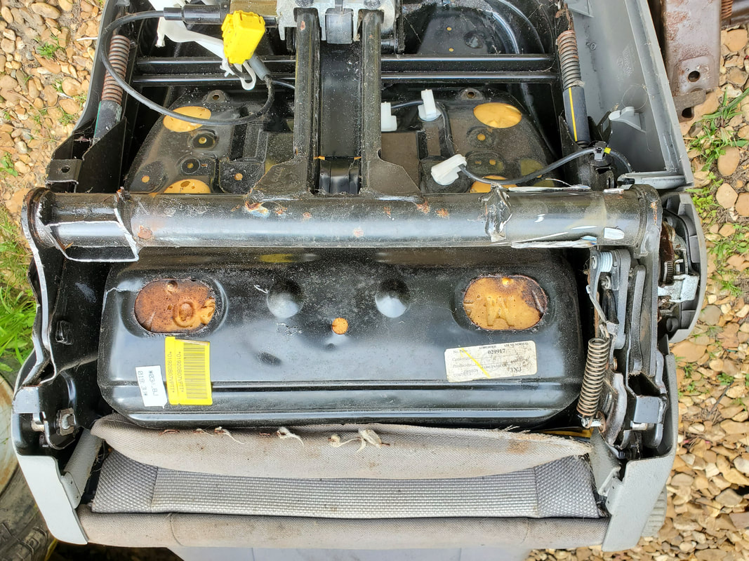
The seats being used were a pair of seats we got for free many years ago. They came from a late model VW beetle and had a weird kind of mount that was made like a T. This obviously can't be used in any kind of way as is so I had to think of something to remedy this situation just as well. 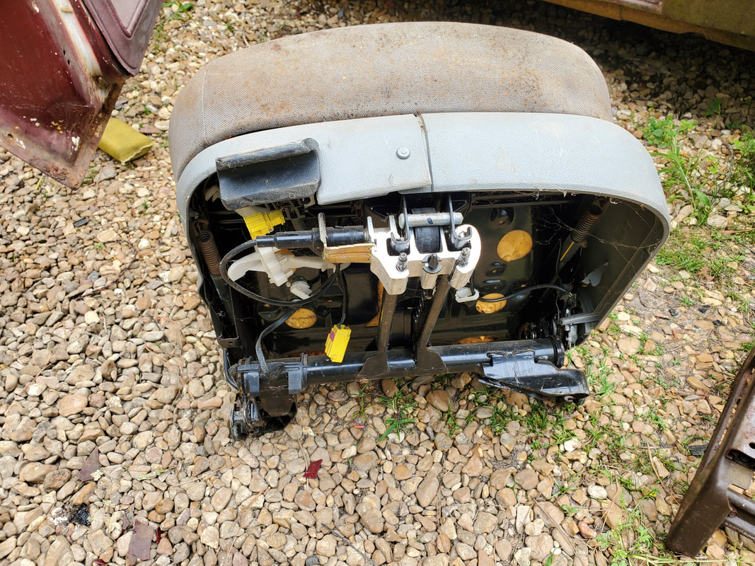
The underside of the VW seat showing the odd T shaped mounting frame.
Now I had a couple options. One, I could fabricate mounts with some scrap metal like angle iron and the like, or, salvage the mounts from another pair of seats like the seats pulled from the minivan. I chose option number 2. I took the bases from the two front seats of the minivan, which weren't in the best shape anyway so there's no loss there if I end up tossing those seats. I would have to do some other stuff first. The first thing is cut the mounting portions on the arms of the T on the seats to provide a clean surface to attach the rear of the minivan seat frames. 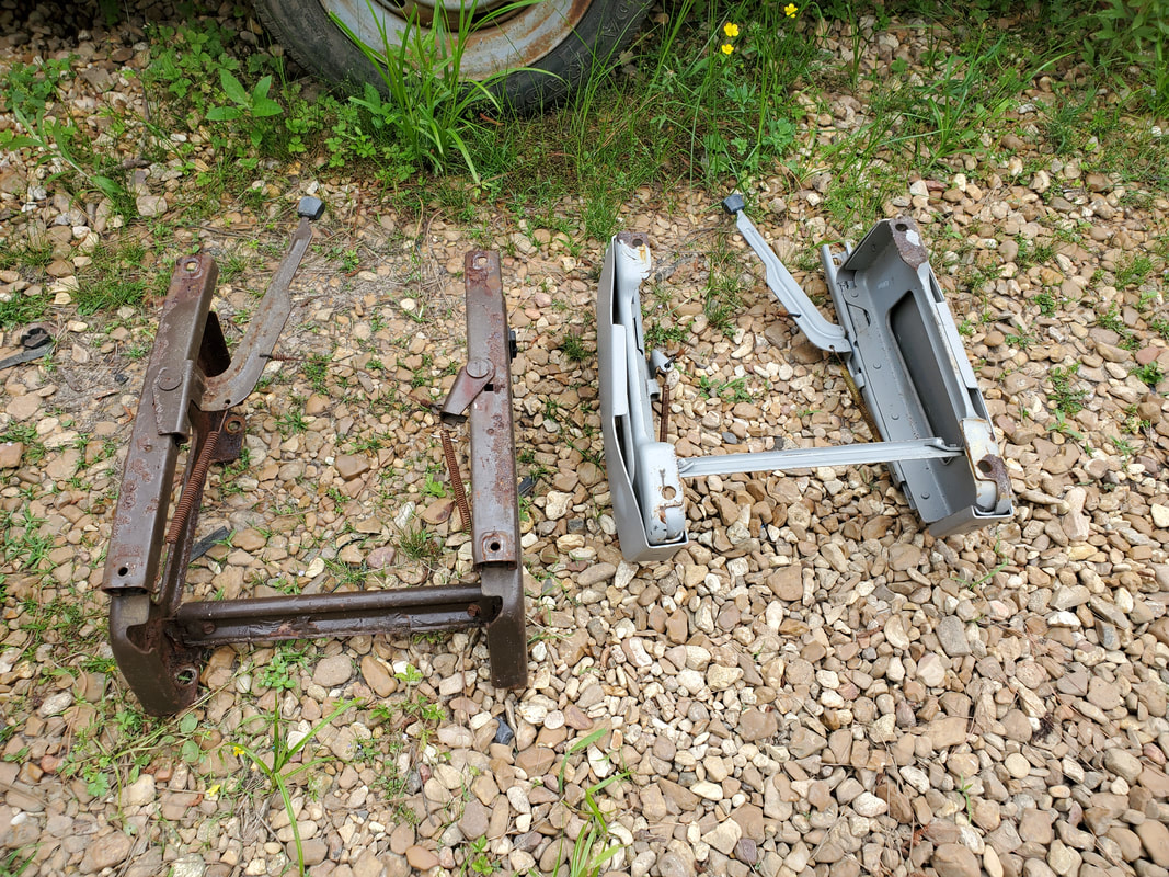
The minivan seat frames salvaged from the old minivan front seats.
Unneeded parts of the VW seat body that were cut away to accommodate the minivan seat frames.
The VW seat frame after removing unneeded material.
With the bottom of the seat prepared, the first thing I did was take the minivan seat frame and set it against the bottom of the T frame. Lining up the rear bolt holes, I marked then drilled two holes through the ends of the arms of the T. This allowed me to bolt the rear ends of the minivan seat mount to the T. With those points secured, I moved to the front mounts. I took a piece of metal shaped like some type of mount for what I don't remember, and drilled a hole a few inches from one end, in the channel portion of the bar. After bolting the bar to one end I then took a measurement of the gap between the rear of the rails to get a reference point so I can know where to position the other rail to match the spacing of the rear end. After drilling the 2nd hole, I bolted that side of the bar down. With that I was able to trim the excess of the ends of the bar to make them somewhat flush with the rails. 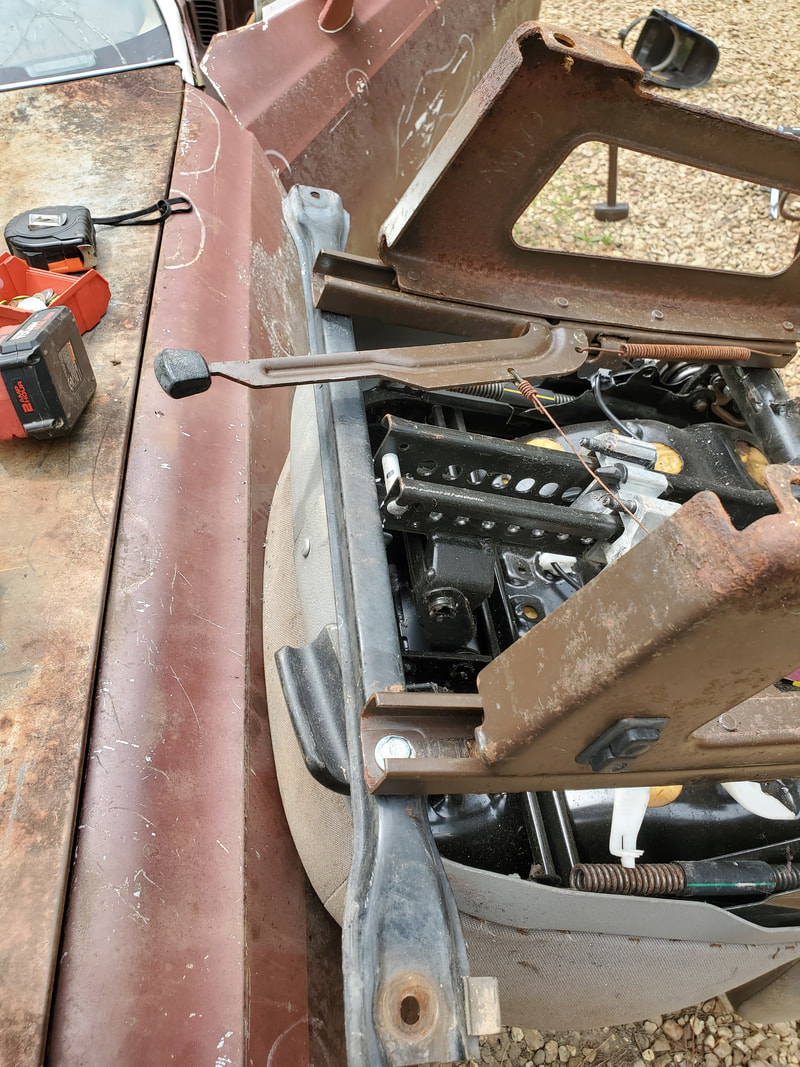
Securing the bar to the front mounts after measuring the spacing and drilling holes.
The last thing I did at this point was secure the bar to the bottom of the T. I did this by cutting a notch on the bottom of the T, at the front of the seat. This allowed the bar to fit in place well enough that I could weld the bar to the bottom of the T. I had to work the sliding mechanism to get the seat frame to slide just enough to make the bar slide into the T. Once I welded the bar to the T, I was done with the main mounting. It is just a matter of test fitting the seat in the car to see if I would need to make any other modifications. 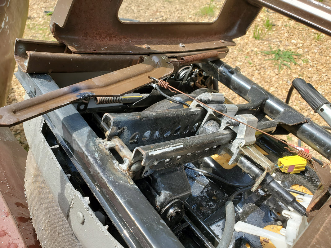
The bar welded to the bottom of the T at the front of the seat. The seat frame is now fully attached to the VW seat.
There's a good chance the seat frame will place the seat too high inside the cab of the Elco. Besides the simple fact that I may not get the seat in the car at this point, I may have to make a modification to the minivan frame. As complicated as I'm making this sound, this mod will basically be chopping out a portion of the middle of the sides of the minivan frame, then welding things back together, making the sides of the frame shorter in height so the seat can fit better and hopefully put my body in a position where my legs aren't too high relative to the steering wheel, even with the wheel tilted all the way up. Worst case I may have to remove the head rest from the seats to help them fit better in the car. Hopefully the seats still won't be too high that our heads will hit the ceiling.
With our work pretty much concluded in the engine bay of the Elco, I turned my attention to the interior. Even though a good amount of work was already done in the interior regarding panels and other trim, there was still the matter of the seatbelt buckles and the seats themselves. The seatbelt assemblies consist of two spring loaded reels with the belt and a male buckle piece on the belt. One reel mounts on the back on the bottom corner of the rear window and the other reel mounts to the floor just behind the outer rear seat mount. I had to remove one panel to gain some access to the mounting point just below the rear window so I could get my ratchet in place in order to tighten the bolt to hold that reel. 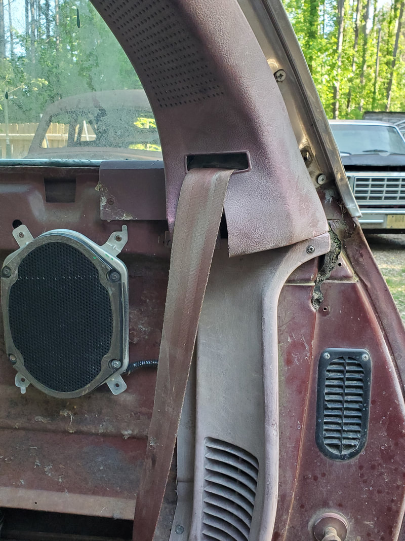 Driver's side upper seatbelt reel bolted in place and trim panel installed in place. I had to determine which seatbelt assembly went to the driver's side. After finding that one, I mounted the top buckle, coinciding with how the male buckle piece would pull out without twisting the belt. After mounting that reel I replaced the molding piece then made an attempt to try and remove the bolt from the floor that would hold the bottom reel. Unfortunately this bolt was well frozen in, and I would more than likely break the torx/star bit before I manage to break that bolt free. More than likely I'm going to end up having to drill out a hole in the floor just behind this mounting point and welding some kind of reinforcement to serve as a strong point to hold the bottom buckle, since a regular bolt hole in the floor would probably cause the whole reel to get snatched out in an accident. This isn't too big a deal as I could use any number of items for a plate of sorts. Once I welded such a plate in place I could drill the hole through the floor then anchor the reel in place properly with a large bolt and nut like a 1/2" sized bolt. 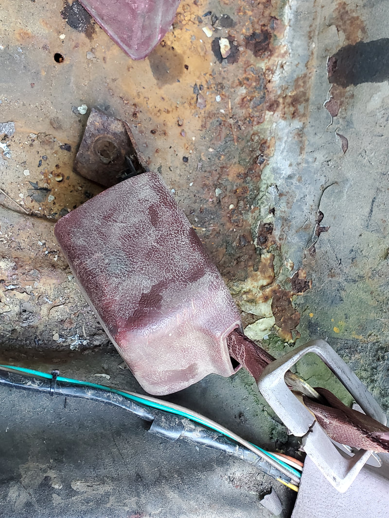 Bottom seatbelt reel with tab for bolting piece to the floor. 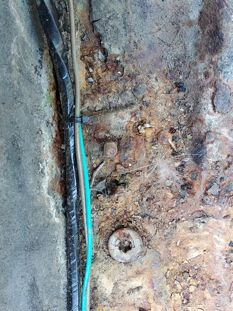 Torx bolt frozen in place in the floor mount where the reel would've been bolted. On the other side the top reel piece went in without a hitch, much the same as the driver's side. As before, the bottom reel couldn't go in, but this time for two reasons. One, the bolt was frozen in place on this side just as well. But the bottom reel for the right side has a broken tab where the bolt hole would've been. Due to rust, this mounting tab was broken short. I'll have to more than likely weld on something to serve as a new tab, something like a large washer that's thick enough to be strong, while using a washer for a smaller bolt, even though the smaller bolt would still be a 1/2" bolt, to secure the tab in place to the new mounting point on the floor. As noted on the left side, I'd have to weld some type of reinforcement plate to serve as an anchor point for the bolt holding the bottom reel. 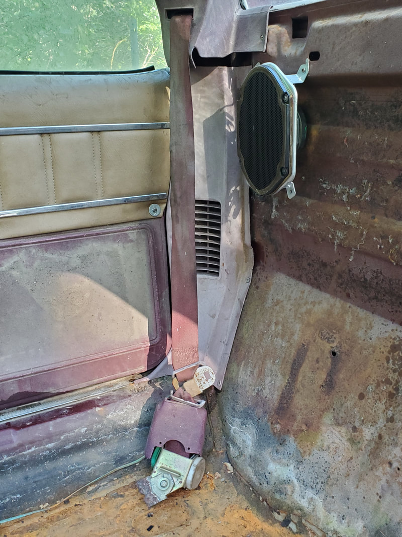 Passenger side upper seatbelt reel bolted in place with panel secured over everything. 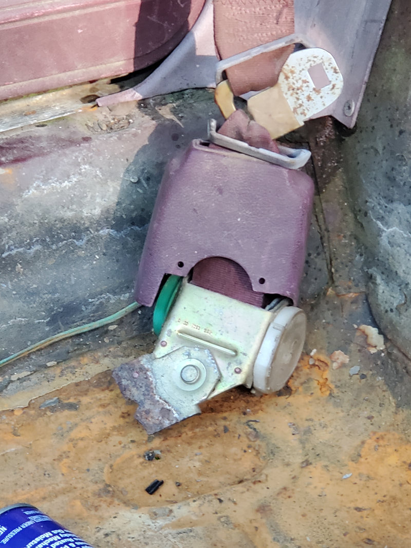 Closeup of the broken mounting tab for the bottom reel. While finishing the full mounting of the seatbelts is postponed until I can do the welding and other work mentioned to get the bottom reels secured, I did go ahead and get the female buckle ends secured in their respective places. Both of these pieces already had their bolts in place. The holes in the floor looked kind of nasty and covered in rust and dirt to the point that I wasn't sure it would even take the thread of the bolts well enough to not strip or break. I did scrape some of the dirt out with a pick then wet everything up, bolt included, with WD40. I slowly worked the bolts in and tightened them down slowly, managing to clear the threads enough to get the bolts fully seated and the female buckles secured. 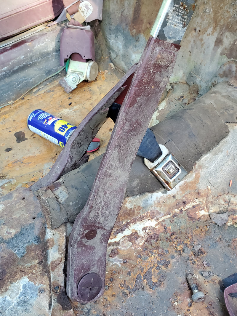 Female buckle assemblies bolted down to center hump in car. I did have to wet one of the buckles with WD40 and work the thing to loosen it up as it was rusted shut where the button wouldn't work. After a little persuasion, I managed to recover the buckle so that was a good save for me. Now I just have to make the mounting points for the bottom reels and weld extra material to the tab stub of the one reel in order to bolt it down. With that the seatbelts will be done. From there will be the seats themselves, , you'll love this when I get to them, these seats are pure gems.
Getting back to the Elco to finish up the assembly of the engine and everything associated with the engine, I left off with the fan/clutch and water pump pulley. I needed replacement bolts for the water pump shaft so once I got those in hand I was able to get that hardware assembled. Since I had the belt for the water pump/alternator, I was able to put that all on and tension the alternator so I can complete that part of the assembly as well. With this all done, I was able to turn my attention to the exhaust manifolds. This wasn't going to go as easy as one would think it should.
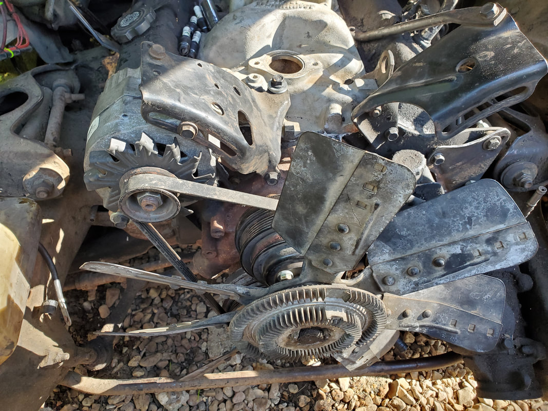
Water pump pulley and fan/clutch with belt all assembled and tensioned.
At first I thought the assembly of the exhaust manifolds would be pretty straightforward with just applying the bolts to the manifolds then inserting the gasket pieces then tightening everything up, but as is the case with most of this shit, nope, it doesn't go easy. Apparently, the cylinder heads used are from an older SBC, from my research, pre-80 give or take. The spacing on the bolts for the exhaust manifolds has one of the ports not lining up with the bolt holes. This is apparently the case due to the fact that one of the gasket pieces has a double bolt slot to accommodate the different manifolds. Unfortunately, the exhaust manifolds I have are for the newer generation SBC's from the early 80's forward. These would not fit as they sit. What this meant was one of two things. One: I could try to source a set of exhaust manifolds or headers that will fit these older cylinder heads, which negates the whole purpose of this switch around of parts. I did this to avoid having to spend a couple hundred bucks on a replacement manifold to go on the center bolt heads. Having to spend the same amount on a set of exhaust manifolds vs intake manifolds would make no sense. This leaves #2: modify the current exhaust manifolds to be able to fit on the older heads. What this would entail is cutting a small piece from the part of the manifold where the bolts go, essentially making slotted mounts versus holes for bolts. 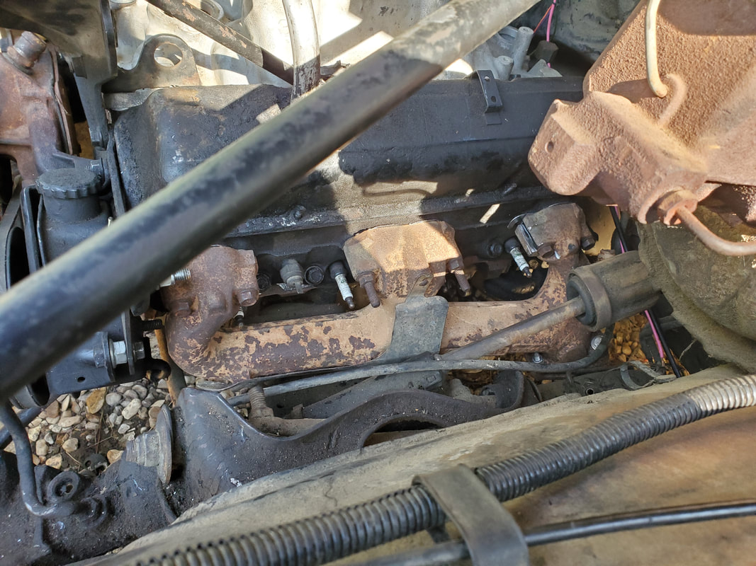
Exhaust manifold on driver's side bolted up after modification.
While one side worked out pretty good with the slot modification since the bolt is technically off center to the outside of the manifold, the opposite side is, well, the opposite. The bolt is actually positioned closer in to the port, which meant I would have to grind some of the metal away to create the clearance necessary for the bolt to be able to go in and grab the threads on the head. This is inherently risky as it creates a thin spot on the port wall between the port wall and bolt hole wall. 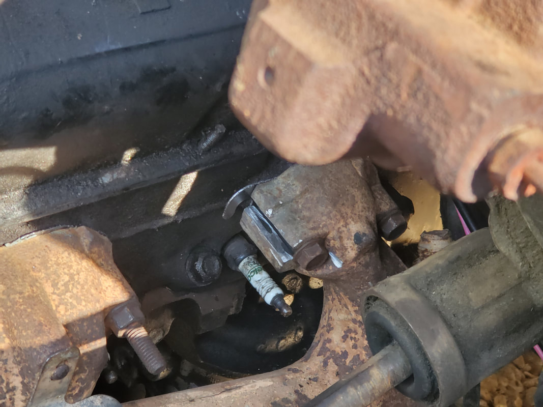
Closeup of the slots on the rear port to help the bolts line up. Note how one of the bolts seems to be closer to the port due to the grinding of the metal to create the spacing for the bolt.
I had to carefully tighten the bolts so as to not strip, cross thread or otherwise break the bolts due to them going in rather tight against the body of the manifold. I was able to get the piece tightened against the cylinder head to sandwich the gaskets properly. I don't know if there are any gaps between the modified part of the manifold and the head as none of that area are fully lining up, but I won't know until I start the engine up. Really, I'm almost expecting there to be a minor exhaust leak, as long as it's not so obnoxious that it blows hot exhaust gas out against the spark plug wire or anything else that could be damaged by the exhaust jet that would result from a large breach in the exhaust passage. 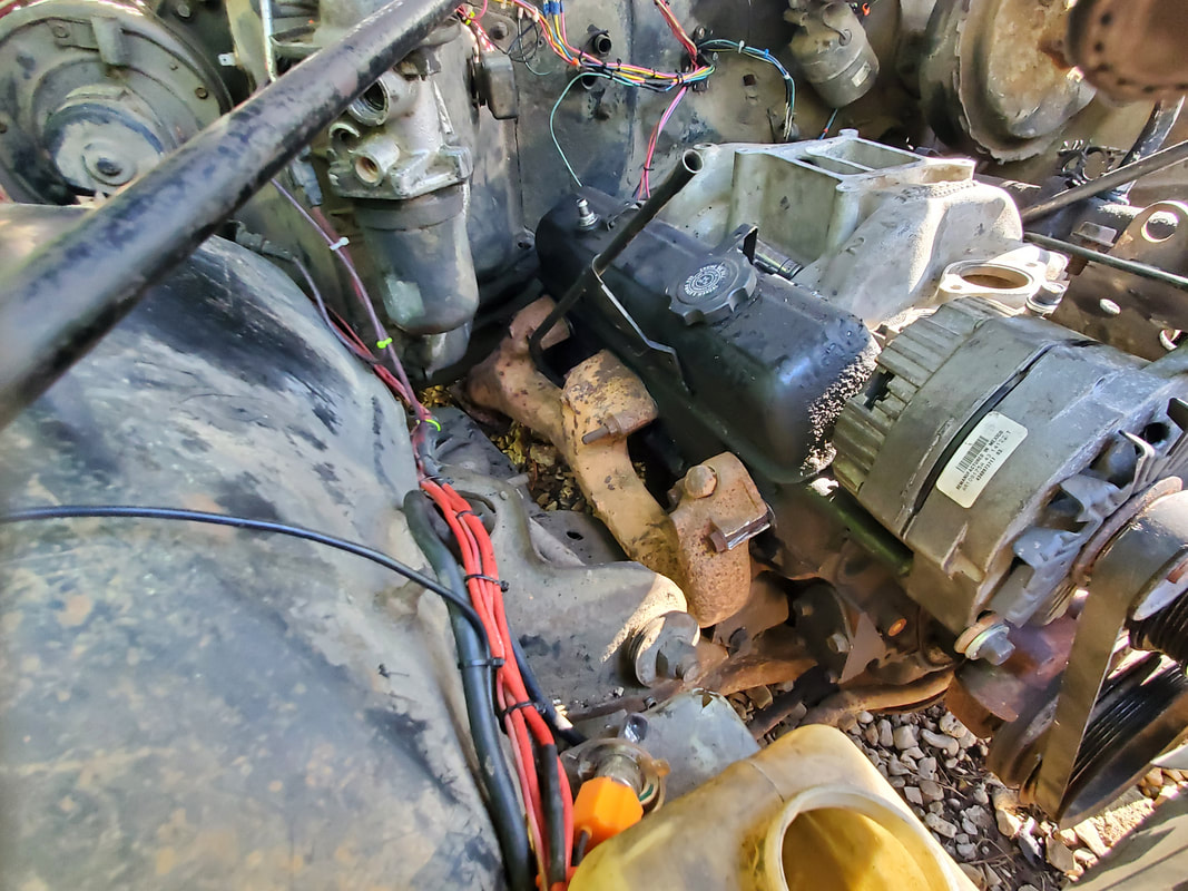
Passenger side exhaust manifold bolted up to cylinder head. Note slotted port on front of the manifold, opposite the driver's side.
On the passenger side, I had to do the same thing on that exhaust manifold as well. Only thing is I ended up doing the modification on the front port instead, since things go to the opposite end on the other cylinder head. It's fine, the concept was still the same, create slots then grind the metal away on one side to give the clearance for one of the bolts. I had to still go easy on the tightening of the bolts to prevent possible damage to the bolts. In the end I did get the exhaust manifold secured to the head properly with the gaskets. 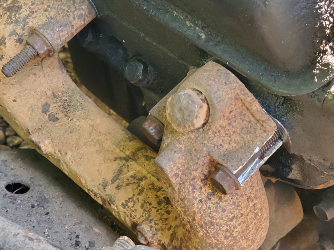
Closeup of the slotted port on the passenger side manifold, at the front this time instead of the back of the manifold. The same rules apply to this piece as the other one.
With the exhaust manifolds bolted up, however bootleg as they may be, I considered that to be a success, allowing me to comfortably move on to the distributor. Even though I don't have any spark plug wires much less a starter to even crank the engine to try and find TDC, I still felt compelled to install the distributor. Since there is no set in stone spot to place the #1 plug wire, I can just bolt down the distributor and when I do crank the engine to find TDC, wherever the rotor points is where #1 plug wire goes. Hell, besides, by installing the distributor, I can get the piece out of the way and in the car instead of sitting in the Mustang where the piece was sitting along with some other parts. 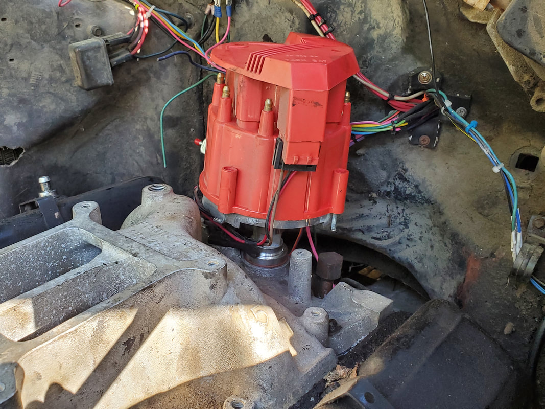
With all this hardware in place, there's a few things left before I can actually attempt to start the engine. I have to still install a radiator and associated hoses. There's still the matter of the plug wires as noted before, and a carburetor. Of course, with the carb I can hook up the fuel line, and of course I can hook up the wires for the distributor, temp and oil pressure sensors. There's also a matter of installing a starter and wiring that up as well. Of course, I still have to install a complete exhaust system. I don't want to start the engine until I have transmission lines hooked up, so the transmission doesn't smoke itself running dry. Of course, I'd have to install a yoke, so the oil doesn't just puke out. Ideally, I'd love to install a driveshaft but these things are pricey so I'd just go with a yoke and just secure the thing in place for running purposes. I also need to install a thermostat and the housing. Sounds like an extensive grocery list but we'll get things done enough to get this engine running.
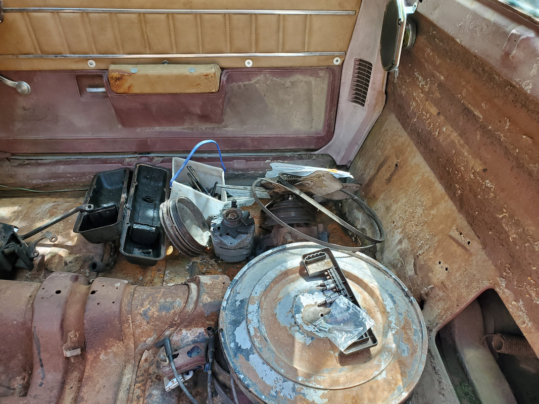
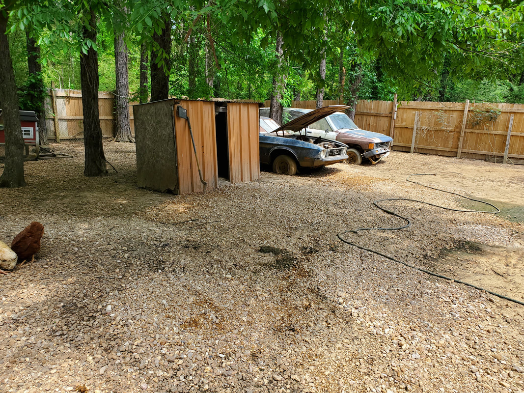
As our work continues on the homestead, the time comes when some older things need to be repaired. In this case, we have some stuff to tend to in the chicken yard. As we've already been covering, the grounds in the chicken yard have been in need of fresh gravel due to old gravel settling enough to expose dirt and mud. Today is no exception as we have another load of gravel to spread out, taking care to cover the wetter muddier spots in the yard. Unlike some areas, we would have to lay extra gravel over the worst areas since the mud will suck up gravel until the mud can't suck up any more rocks. We had this same problem while covering the Midway where we had to lay multiple layers of gravel over the worst spots in the driveway until the ground couldn't absorb any more gravel. 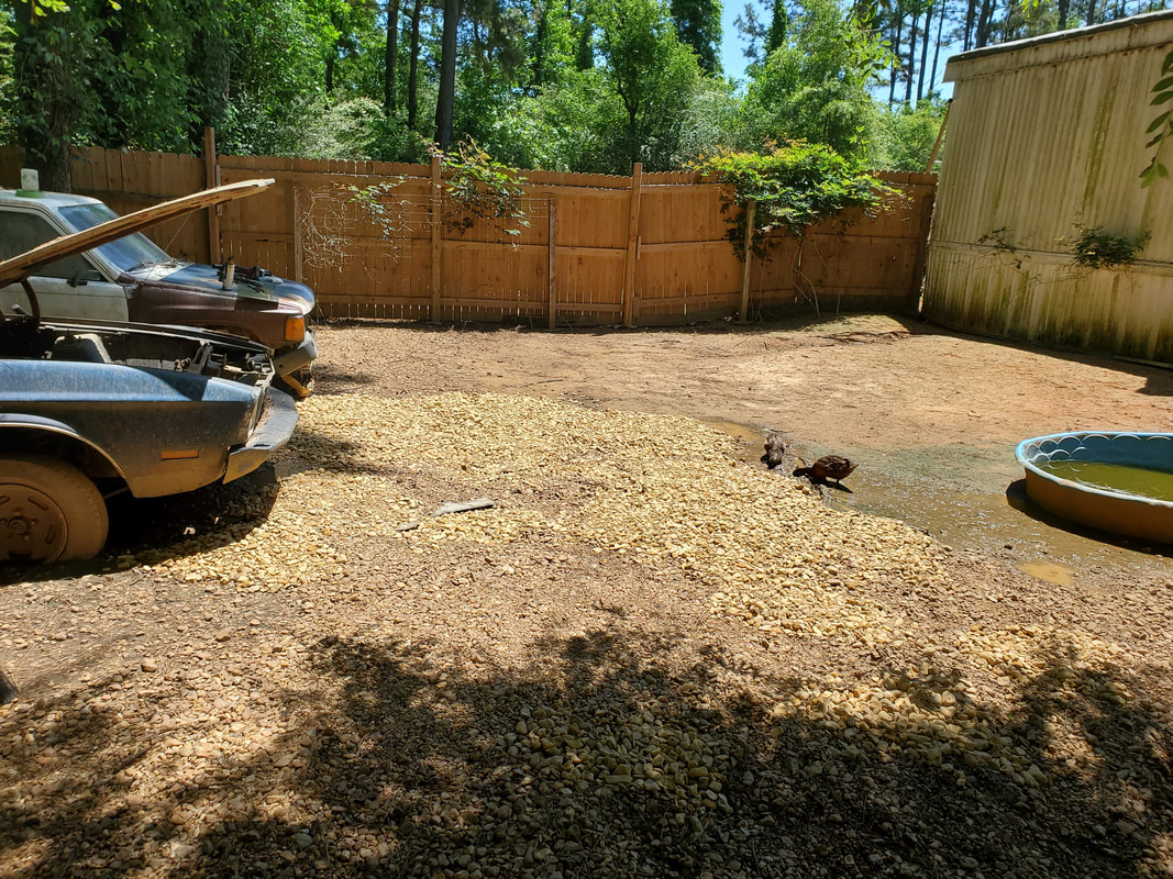 Middle of the chicken yard where the worst spots were, as seen by the wet areas, covered by fresh gravel. The main thing that we had to give our attention to was the floor in the brooder area of the Mustang Chicken Coupe. Pieces of the sheet metal floor were rusting away enough that there was no floor. With a little pressure the floor fell away in two spots. I had to patch this up, especially since we had four turkeys that were getting too big for the brooder box and would have to go to the Mustang Chicken Coupe's brooder area. 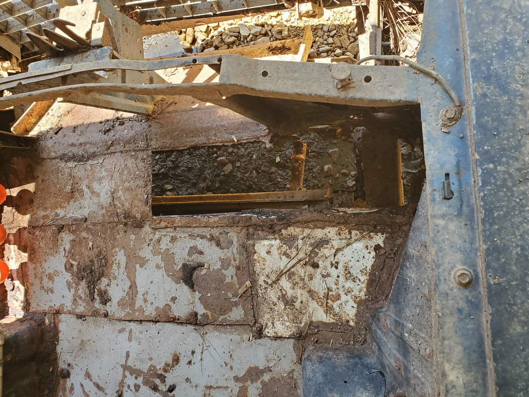 Section of the floor at the front right end of the brooder area that was cut away to get rid of the rusted out metal from this section of sheet metal floor.  Cut out pieces of rusted sheet metal from the floor. I started off with cutting away the section of the rusted out sheet metal that I would be covering. Once this was taken care of I sourced a piece of sheet metal from the scrap pile that would replace our rusted out metal. I had to cut and trim the ends and fit the metal in place, working the tabs that I created on the ends until I had the sheet metal shaped to fit. The tabs would be used as anchor points for the self tapping screws I'd be using to attach the piece of sheet metal to the rest of the floor. The piece of sheet metal was just a tad short so I had to use some of the leftover scrap to cut a tab to cover the exposed section, again, using self tapping screws to attach this metal as before. 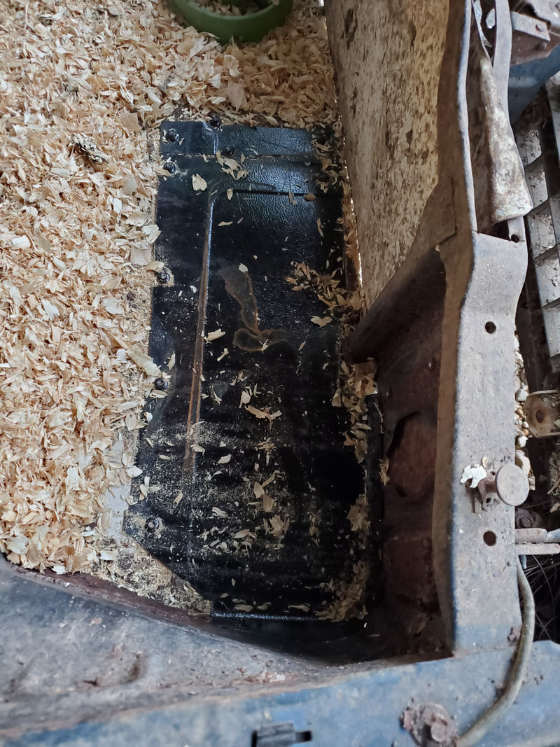 Sheet metal panel attached to floor, shavings are already spread over some of the area in preparation for the turkeys. This was taken after addressing the other area that needed addressing in the brooder area. On the right side of the brooder area, same as the first hole, was another hole forming, this time on the back end of the brooder area. This area was just like the first area, a small section of sheet metal that was rusted all to hell. Only problem is this section was partially welded against the firewall and the adjacent sheet metal panels. I had to cut away all this bad metal as well. Same as before, I'd have to form a piece of sheet metal with tabs to fit in place and attach this with sheet metal screws.  Right rear section of the brooder area cut out to clear the rusted metal prior to attaching fresh metal. As before, once the metal was shaped and trimmed to fit, self-tapping screws attached the sheet metal to the rest of the floor. With the metal in place, since it was already warm out, I removed the heat lamp since it wouldn't be used and leaving it in place would risk its damage when its not on as the birds would be more prone to jumping on it. Shavings were added and the birds were brought out to their new home. 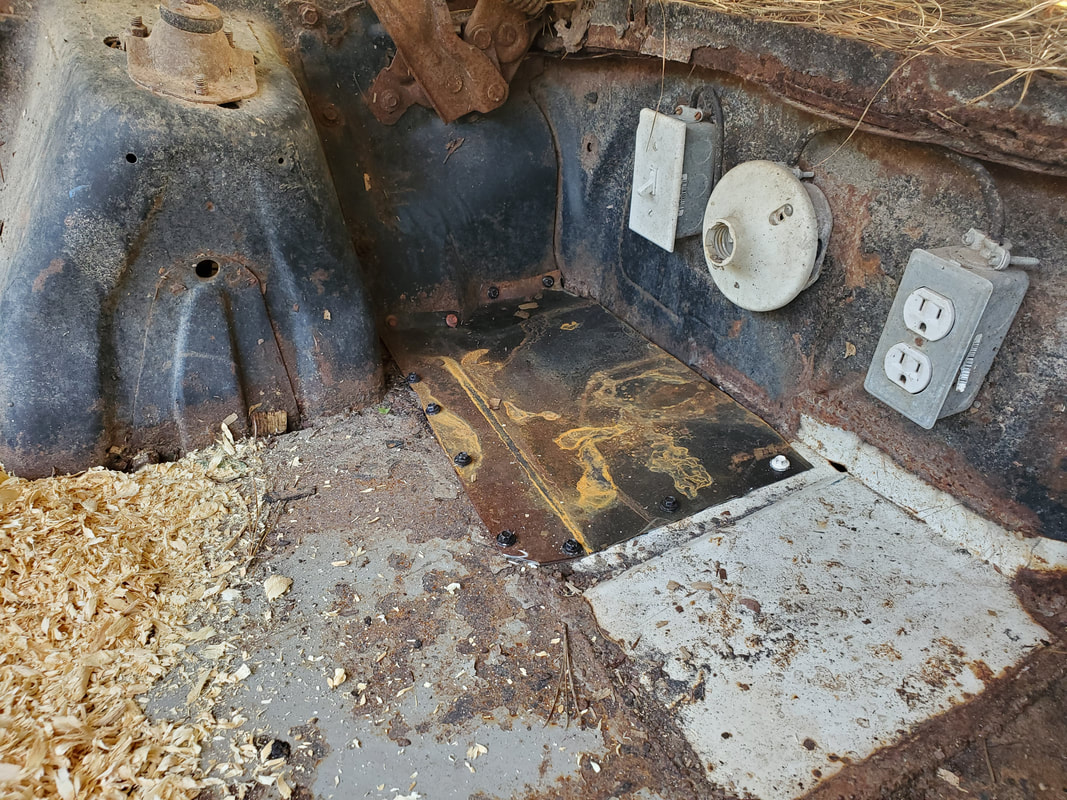 New sheet metal panel screwed in place at the back of the brooder area. 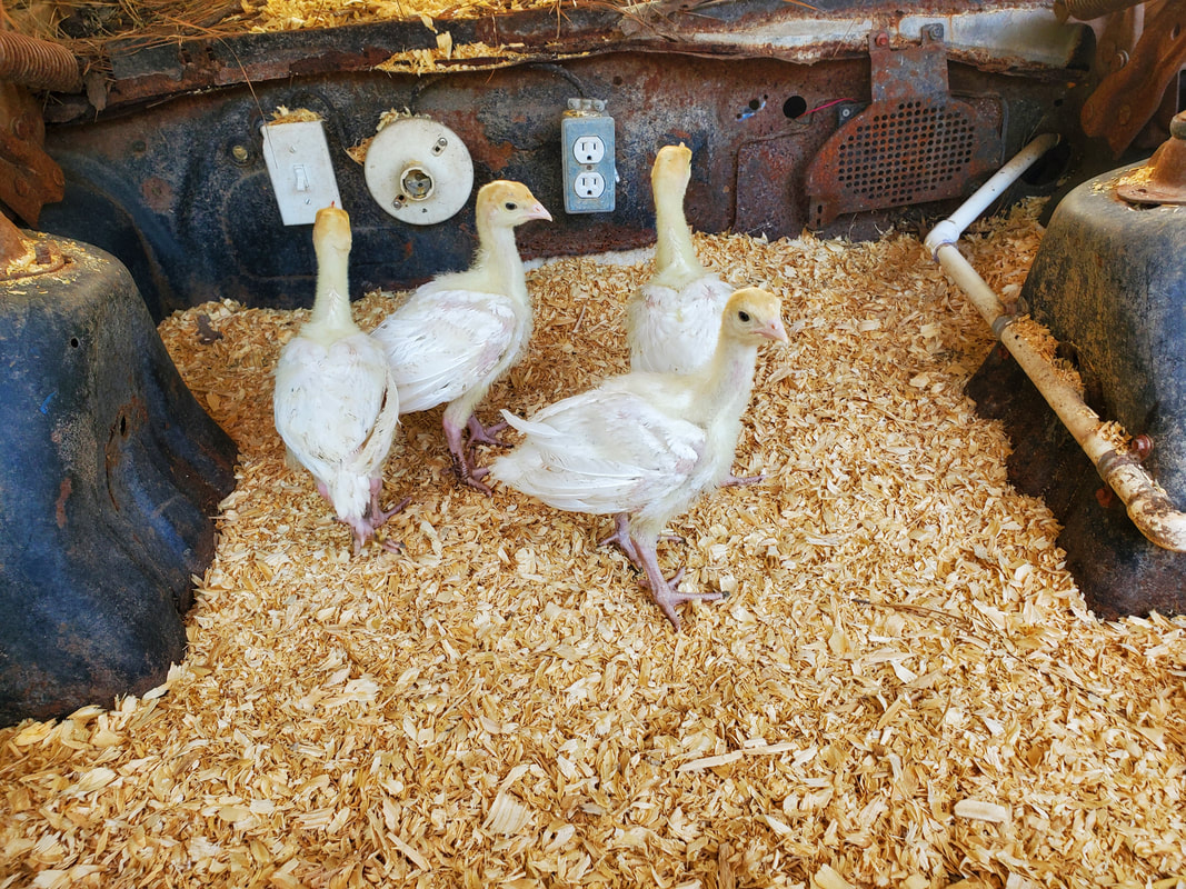 The baby turkeys transplanted to their new home before they reach the size and age to be released into GenPop. With the floors patched and the turkeys moved into their new lodging, I can turn my attention to other matters around here, like getting back to the Elco. There's still some other odds and ends on the Mustang Chicken Coupe to tend to, like retrofitting the water system to be like the other two car coops where the pressurized part of the system only fills a reservoir in the form of a bucket which will gravity feed into the main watering system that feeds the drinker cups. The main watering system and drinker cups require super low water pressure to the point of being no pressure. Main thing is, by retrofitting the Mustang Chicken Coupe's system to be like the others allows us to be able to use the system in an offline mode where the bucket can be manually filled with water to still feed the drinker cups, such as in an off grid situation. There will be more to come on this as well as other things. I left off with the engine assembly at the point where I had to try and figure out where to put what I thought was the last accessory bracket onto the power steering pump. After not being able to figure out any configuration for placement of this bracket I had to do some more research. When I couldn't turn up anything definitive, I had to put my eyes on the old engine as well as the garage to see if I may have overlooked another piece. After not finding another piece, I ended up looking at the power steering pump more. It was then that I realized that the bracket piece in question was actually another power steering pump bracket that mounted on the front of the pump and was the Monte's old PS pump bracket from when it was in a similar V belt configuration. This bracket mimicked the outer half of our current PS pump bracket. Now, all this meant was that I had no idea where or if there ever was another bracket for the PS pump to hold it outside of the two mounting points at the water pump. This still leaves the question as to what to do with the gap between the outer end of the PS pump and the bracket mounted on the cylinder head. 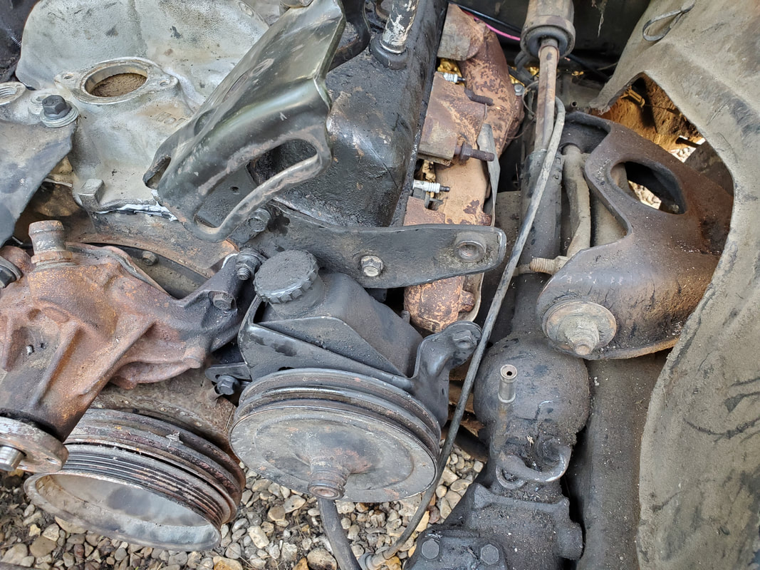 The power steering pump with the gap between the outer end and the head bracket. This needs to be filled in with something. 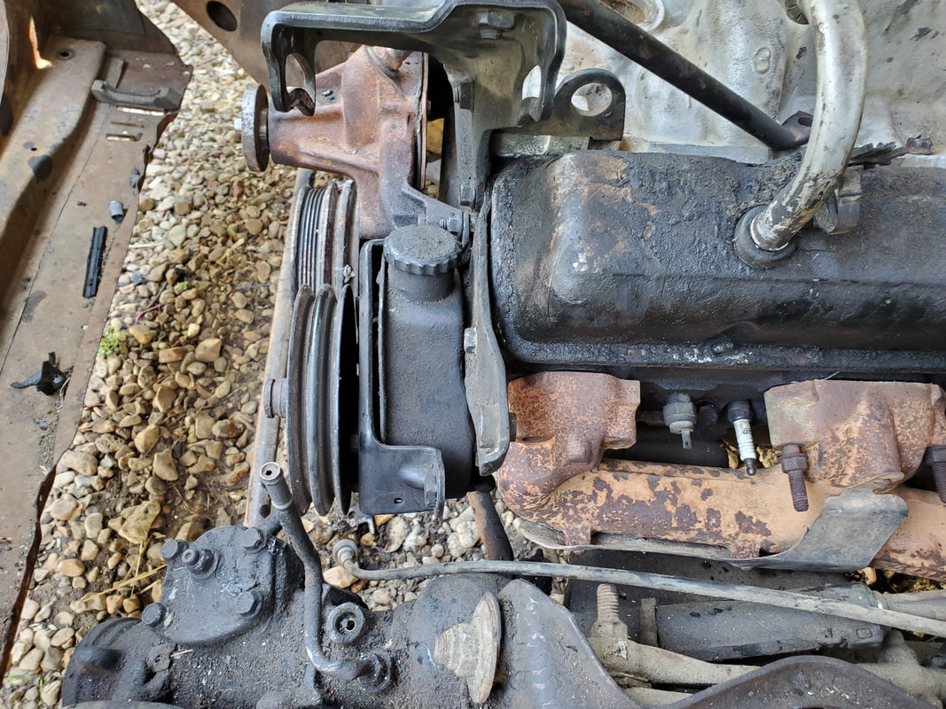 A side view of the gap that needs to be filled between the PS pump and cylinder head bracket. I ended up coming to the conclusion I will have to fabricate a bracket. Luckily, I had some old brackets that I removed from the Ford 302 engine that I later put in the FMT. These brackets were part of the V belt configuration that was set up for the truck or car that this engine used to be in. One of the brackets has a curved slotted hole for adjustments of tension on an accessory. I planned on using this bracket as my donor bracket. I would have to do some reconstructive surgery on this piece though. 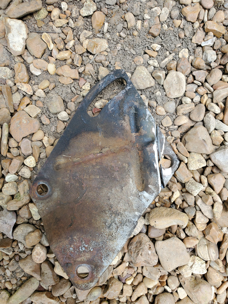 The older Ford accessory bracket with a tab already cut free in order to start the test fitting process for our SBC application. I started off with trimming a corner from the bracket piece as the placement of the bracket depended on the corner piece being out of the way. After this initial trimming I then moved on to drilling a couple holes. These holes would line up with the two outer holes on the head bracket to hold it in place solidly. Even after drilling the holes I would still have to use spacers in the form of multiple washers to mount the bracket to the head bracket. The other hole would be covered with a regular nut and bolt combination to hold things together. One of the holes on our new bracket would also line up with the hole on the PS pump bracket to hold a bolt. It too would need a spacer to cover the gap between the two. 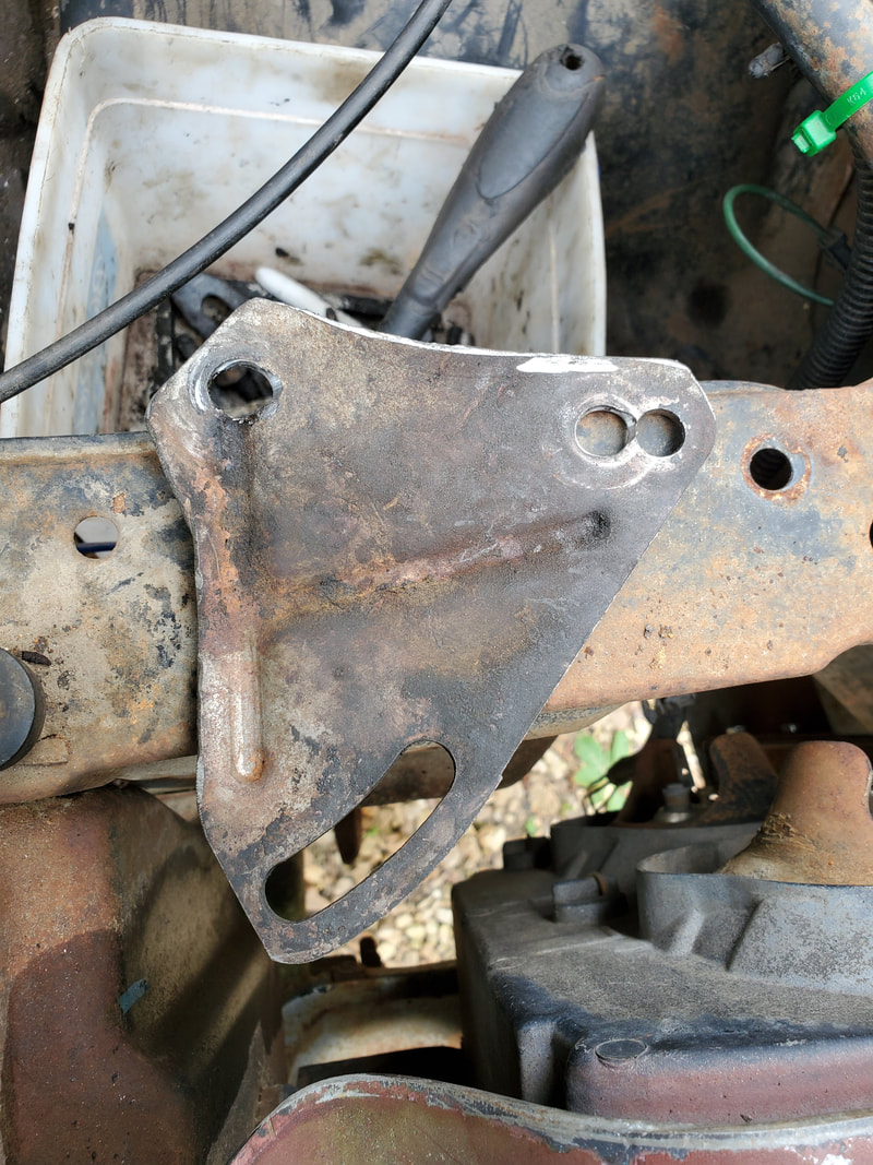 The completed bracket after doing the cutting and drilling and test fitting. After drilling out and sizing up our holes and doing multiple test fittings, I had to trim some more material from the bracket to allow the bracket to fit and still allow the PS pump to be adjusted out to tension the belt. There was also a ridge on the bracket I had to grind down in order to allow the bracket to fit straighter. With all our "adjustments" made, and test fittings done to confirm fitment, I was finally able to bolt everything together. Using the washers for spacers on the bolt that held our new bracket to the cylinder head and using a long bolt with lock nut and lock washer, I was able to secure the bracket nicely against the cylinder head. I then used a large nut as a spacer along with a bolt to secure the PS pump bracket to the new bracket. This bolt would pass through the curved slotted hole for adjustment. 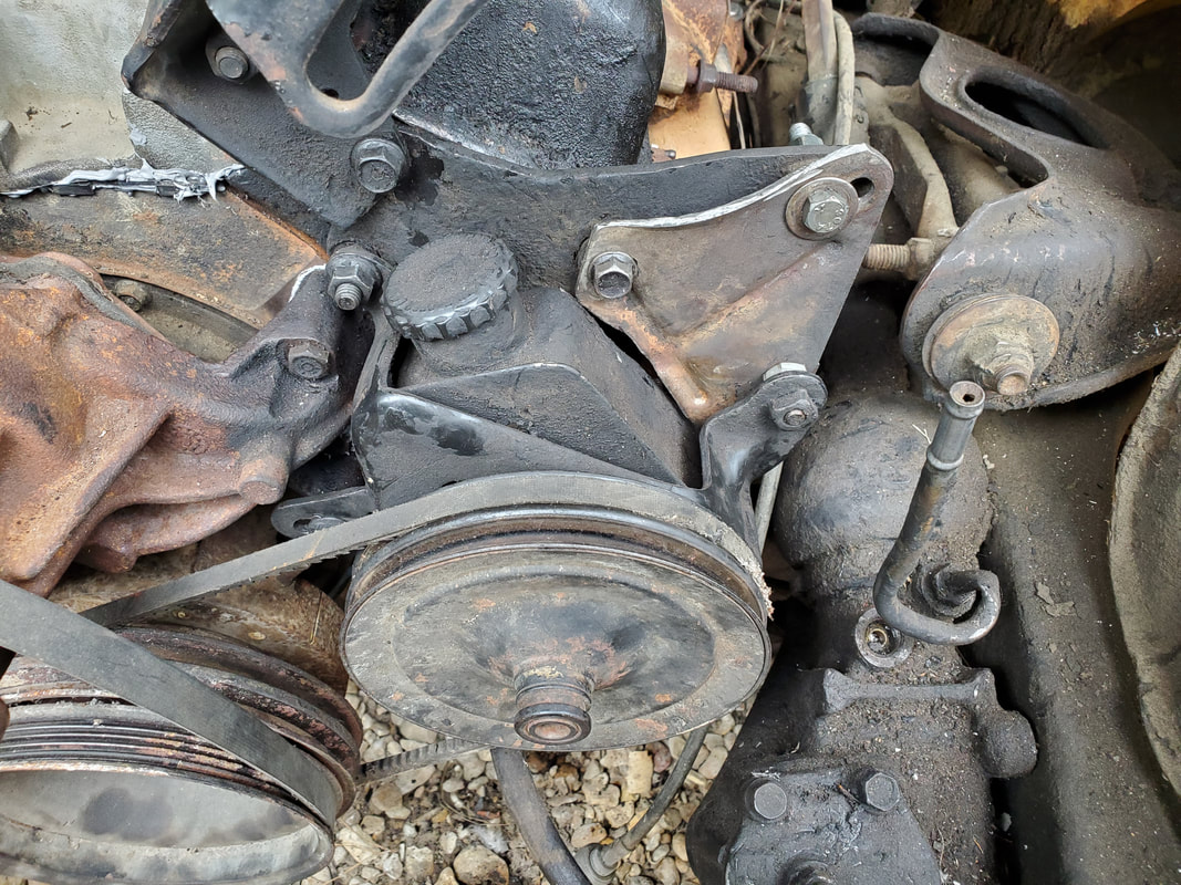 Power steering pump mounted securely with new bracket, using bolts and nuts and washers for spacers. I was able to tension the PS pump against the belt and even after putting as much tension as I could, I still had 1/3" of spacing between the PS pump and the new bracket. I figured that a new belt would be tighter and probably give even more spacing between the PS pump and bracket. Everything appeared to be nice and solid. I was able to pull and tug on the PS pump without it giving in any direction, proving that the new improvised bracket worked like a charm and would serve its purpose to hold the PS pump while the engine was running. 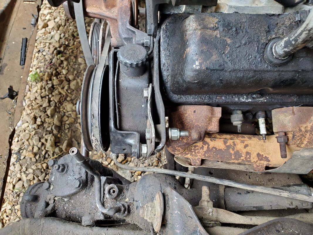 A side view of the new bracket showing the spacers and bolts used to hold everything together. With our PS pump bracket issue resolved, I can finish things up with the mounting of the fan/clutch and pulley on the water pump, as well as the exhaust manifolds and associated gaskets. A couple other little mop up things like mounting the distributor and thermostat housing are all that's left before I can really consider the engine reassembly done. There's of course going to be things like heater hoses and wiring for the dizzy and temp/oil sensors along with other things that I'd address later as more parts are supplied. Things like a fresh carb, exhaust pipes, radiator, rad hoses, etc, are all things that will need to be sourced to finish further assembly, like fuel lines, etc. Really we're in the home stretch on getting the powertrain ready. Moving along with the engine reassembly, I had to attach the water pump. This involved gluing on the gaskets then bolting the assembly on, after I had removed the fan/clutch and pulley to make things easier. One of the bolts on the water pump requires gasket maker to help seal it due to the fact that the bolt hole passes into the water jacket on the block. After bolting the water pump on, I had the pleasure of trying to figure out the layout of the accessory brackets as this stuff comes in multiple pieces, unlike the serpentine setup. 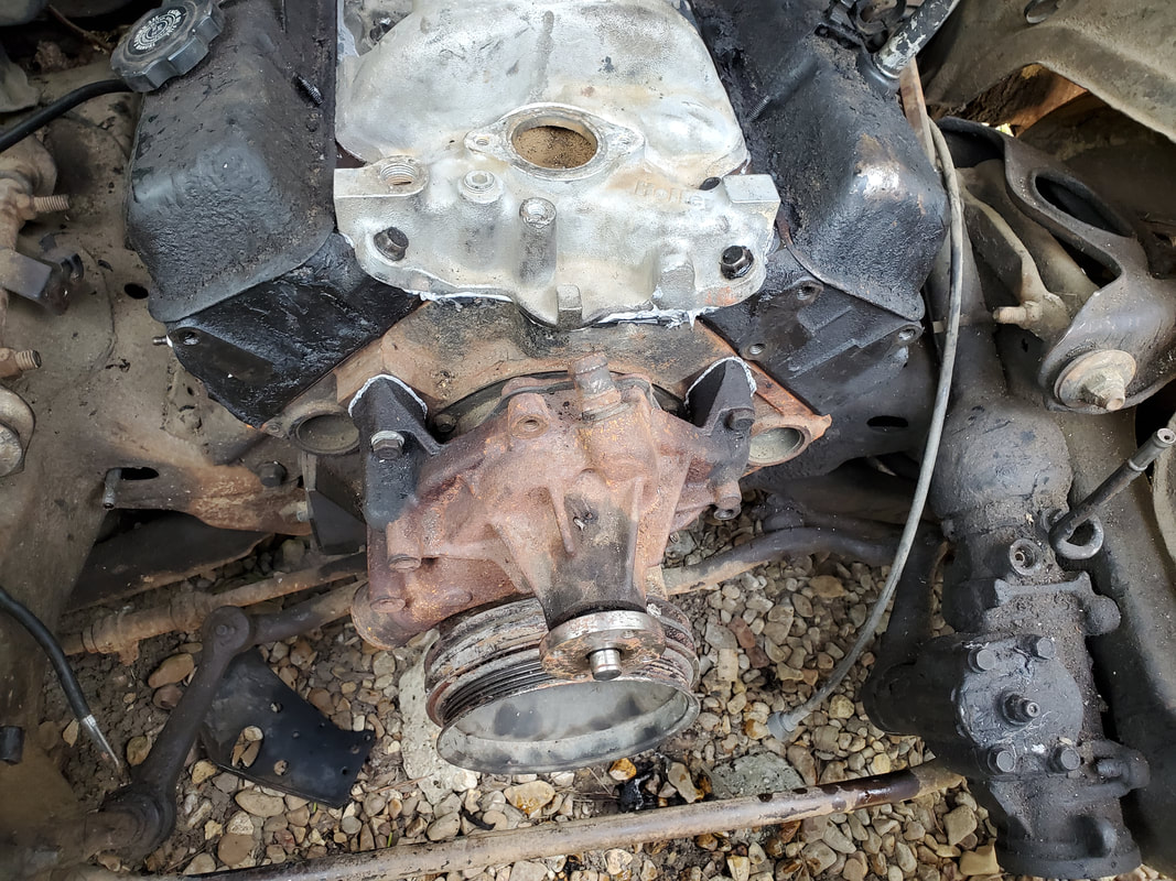 Water pump bolted to engine. I wanted to start with the power steering pump assembly. This fun piece includes the pump itself, which already had the main bracket bolted on, along with an intermediate piece and the AC compressor bracket. I don't have the compressor but will still need that bracket for when I do get around to installing AC on this car. I had to play around with the fitment of the brackets until I finally figured out the sequence of assembly for the brackets. Now the fun part about the AC bracket. Due to its design, it was made to fit on the stock intake manifold. Since we're using an aftermarket unit, it was just as well that the placement would not allow for the bolt tabs on the bracket to line up. I ended up having to use the angle grinder to whittle away material from between the bolt tabs to open the gap up enough to allow this bracket to fit around the body of the aftermarket intake so the bolt tabs line up.  AC compressor pump after cutting away material to allow the piece to fit on the aftermarket intake manifold. With the AC bracket attached fully, there was a bar or rod that attaches to another point on the intake. Just like with the other mounting point, it too did not line up. I will have to come back to that rod to whittle away some material in order to line the bolt holes up so I can bolt that down to the intake to attach that piece. While it isn't needed immediately since there's no AC compressor, it will be needed for the added support once a compressor is attached. PS pump and AC compressor pumps and associated brackets attached to engine. One more piece still needs to be assembled behind the PS pump to secure it and allow for tension adjustment. Note the exhaust manifold is hung in place in order to help figure out placement of the bracket. There is a problem, however. I have one bracket piece that I can't quite figure out where it goes relative to the other brackets around the power steering pump. I know that one of these brackets are actually attached to the front bolts on the exhaust manifold on the driver's side, but with this particular bracket, its design doesn't seem to allow for any placement that I can see right off the bat. The bracket in question appears to need to be slotted to allow for the movement of the PS pump for belt tension. I'll have to check the garage and the old engine to see if I missed one piece during the disassembly a while back. In the meantime, I did jump over to the alternator bracket. 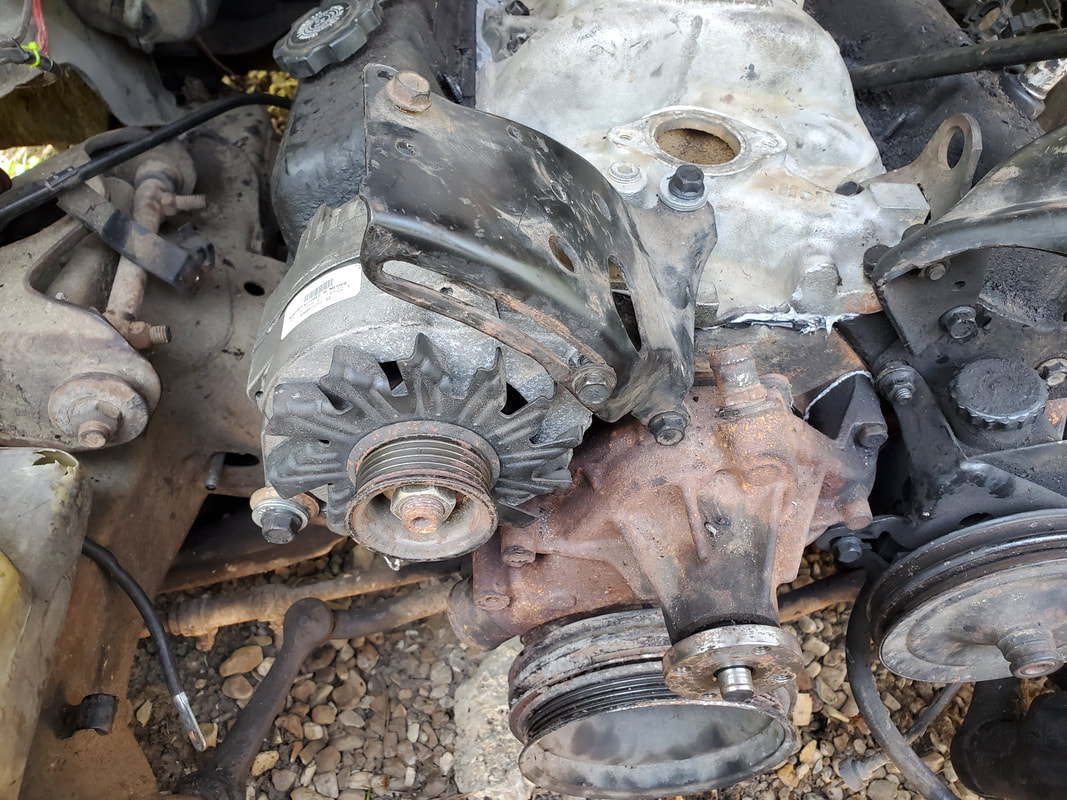 Alternator and associated bracket attached to the engine. This bracket, unlike the other ones, was actually pretty straightforward in its attachment. One bolt on the top of the water pump and another into the top of the intake held the bracket on. Upon hanging the alternator, one long bolt holding the bottom of the unit to the cylinder head was attached. One more bolt on the top of the alternator in the slotted portion of the bracket fully secured the assembly. Of course, none of this could be tensioned due to the rest of the pulleys and the belts being assembled so these components can be secured all the way. I did take a moment to swap crank pulleys while I was at it so that too is one more thing out of the way. In the meantime, I still have to figure out the rest of the PS pump bracket situation. If I don't have another piece that's needed or can't figure out the exact position for the piece I do have, I may have to fabricate a bracket through the cutting and welding back of what I have. Once that's done, I can then put the fan/clutch and pulley on the water pump then add the belts so I can finish up the accessory reassembly on the engine. With the surfaces prepared on both the cylinder heads and the top of the block, it was time for the head gaskets. Using the pegs on the ends of the block, I seated the gaskets, then carefully seated the heads on top of both gaskets. From there I applied all 17 bolts into each head, snugging them down before doing the torque sequence, three times. I had to go to 25 ft/lbs, then 45 then 65. With that done I can get the push rods and intake gaskets down. 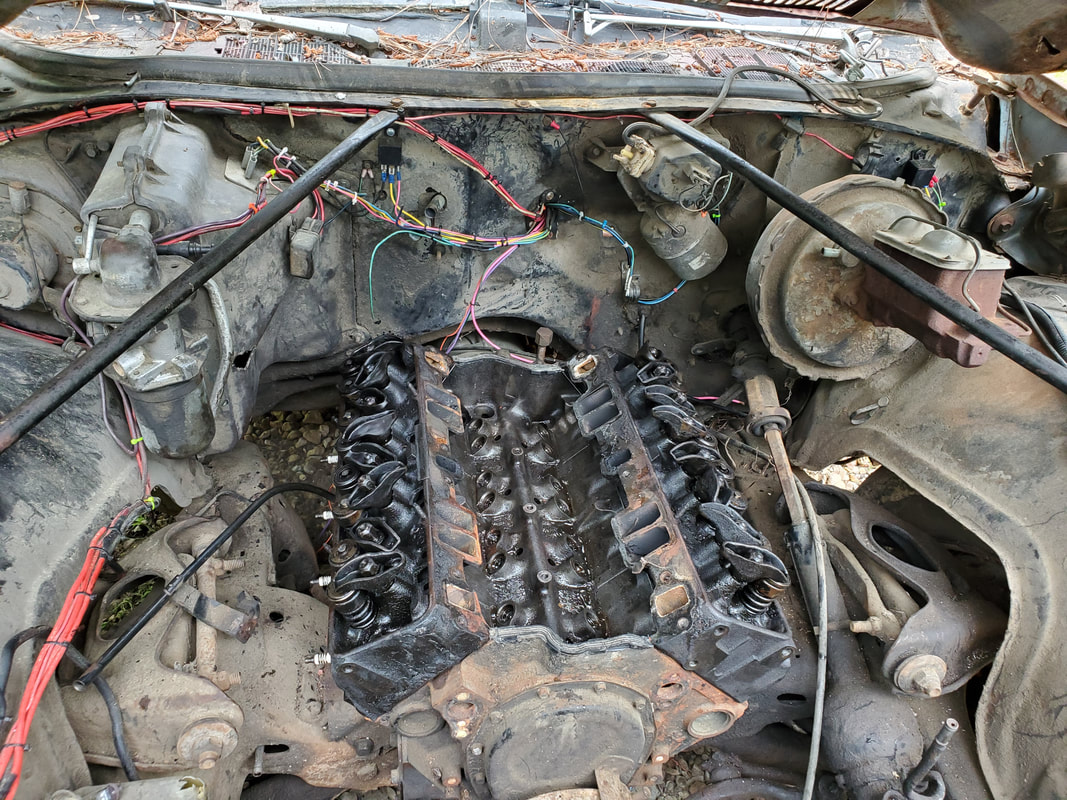 Cylinder heads mounted on top of engine with fresh gaskets. I had to loosen some of the rocker arms on the heads to get them out of the way enough to seat the push rods. Unlike Ford heads, I have to do a valve lash adjustment, where I have to turn the engine until the particular rocker arm has no pressure on it due to being in the fully closed position, then use a feeler gauge between the valve stem and rocker arm to tighten the rocker arm nut until there is a certain amount of gap between the two. In some circles after the gap is achieved, a slight turn more further seats the rocker onto the valve stem, that way there won't be any flutter between the rocker and valve stem, while not applying too much pressure on said valve stem. 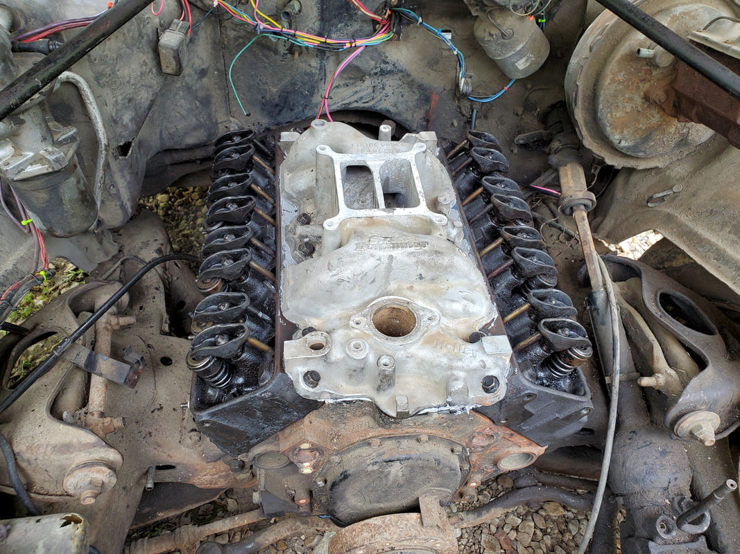 Intake manifold mounted along with push rods mounted under rocker arms. With the push rods down I glued the intake gaskets into place on the heads. I previously scraped the old gasket material off the heads and intake in preparation for the new gaskets. With the intake down, I installed the bolts then tightened them, going back over them several times to ensure that all the bolts are snug and secured. We've already seen how an intake will shift when one bolt is tightened then cause another bolt to loosen up so its important to go over the bolts several times to ensure all are tight. From here I can start mounting the accessories. This starts with the water pump. As with the other components, I salvaged the complete water pump, pulley and fan/clutch assembly to use on this engine. Since the other components were salvaged, it's only smart to use the water pump and pulleys as well. I do have the same hardware that I removed from the Monte a long time ago but I'll save that stuff for the other 350 engine I have in the garage. 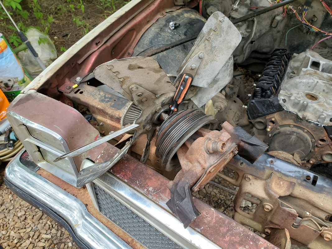 Water pump assembly with fan/clutch and pulley, this will be disassembled before installing. I will have to make a couple gaskets for the water pump as I don't think I have any spare units on hand, but that's fine, I should have enough paper on hand to achieve this. In the meantime, I did separate the fan and pulley from the pump to make it easier to install the pump. I also wanted to replace the studs with regular bolts to make removal easier in the future when the water pump needs replacing. 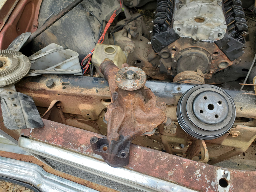 Water pump after separation of other components. Another thing that I'll get installed right after the accessories is the exhaust manifolds. I have a spare set that happen to have a short piece of the flange pipe attached, which will make it easier to fabricate an exhaust system as I can just chop off the donor pieces from a junkyard vehicle or two in order to piece together the exhaust system. Since most of the vehicles at the junkyard have a single exhaust pipe setup, I'll probably have to cut the systems from two of the same vehicle, so I can have symmetrical runs of pipe and mufflers for use on the dual exhaust system for the car.  Exhaust manifolds with pieces of flange pipes installed. These will be used to make piecing an exhaust system together that much easier. When I do get the pieces together on the engine, I can seat the distributor in place, maybe trying to get to TDC for #1 cylinder and seating the unit in place, otherwise I can just say fuck it and mount the thing and wherever the rotor points is where #1 cylinder will be. Either way, with the engine reassembled, the next move will take me back inside the car to install the seatbelts and the pair of old seats I have in the garage, getting us that much closer to finishing this car, even though we have a long way to go before actually finishing the thing.
After going for so long without even so much as lifting a single part on the Elco, the time has finally come for me to get back to work on this car. Where I left off, I was trying to put an intake onto the engine that I had, only to find out that the intake was for the older generation engine that has the heads with the valve covers that have bolts on the lip of the cover. Because of this, I had two options, either spend a couple hundred bucks on another intake that will fit the newer generation heads, or snatch a set of heads from one of the other SBC engines we have in the garage, that happen to be older generation engines. Besides, I also needed the accessory brackets and accessories to equip an engine, which one of the older 305's happen to have. So it was settled, take the heads and accessories from the old 305 and remove the newer style heads from the Elco's 305 and install the older gen hardware on the block. At least this way the only cost I'll incur is for the head gaskets and intake gaskets.
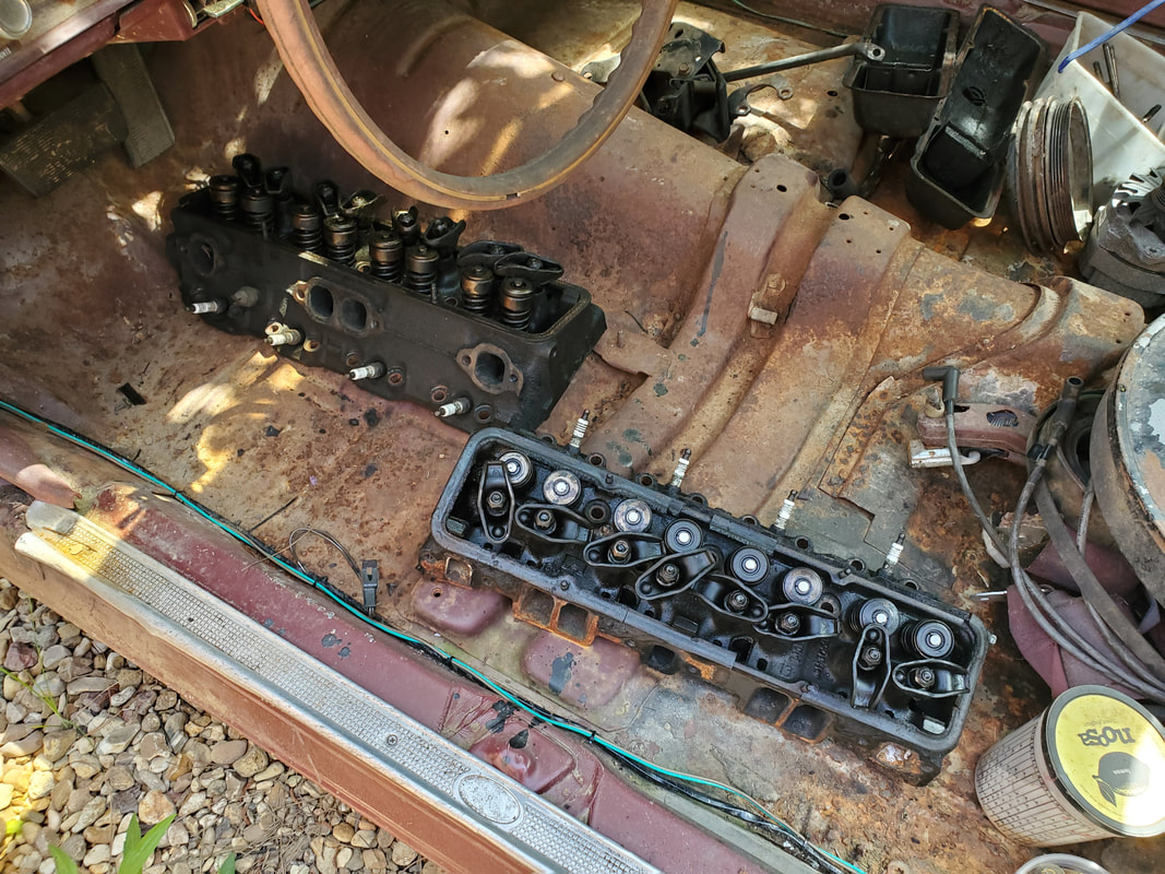
The set of older generation cylinder heads removed from an older 305 for use on the Elco's engine.
The accessories and brackets also removed from the older 305 for use on the Elco to set up the whole engine.
On the Elco I had to remove the exhaust manifolds first, then remove the rocker arms from the heads in order to access one of the rows of head bolts. The exhaust also covered the outside row of head bolts. I do have a spare set of exhaust manifolds with a short piece of flange pipe that I planned on using in place of the current exhaust manifolds. Reason for this is the idea that with the piece of flange pipe I can more easily attach couplings and pieces of exhaust pipe to piece together an exhaust system versus having to source a system from a junkyard truck that included the flange pipes from the exhaust manifolds. But in the meantime, the heads have to come off. 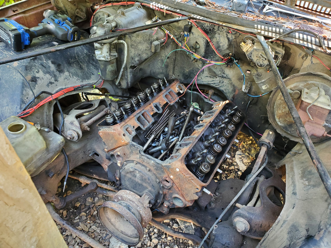
Engine top end with exhaust manifolds removed and rocker arms off. Note the pushrods and head bolts in the lifter valley of the engine block.
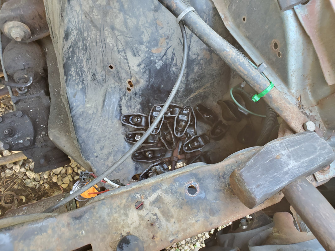
Rocker arms set aside along with the exhaust bolts, prior to placing in a container for safe keeping.
I was able to use the impact wrench to remove some of the head bolts but had to use a breaker bar and socket along with a regular socket to remove other bolts that were in spots where the impact couldn't reach. With the head bolts off I was able to use a hammer to lightly tap the heads to unseat them from the top of the block. With the heads off and en route to the garage for use on the same 305 block I removed the older heads from, I was able to see how things looked inside the engine. The cylinder walls all looked good. There was no large level of rust anywhere that would suggest any other internal problems. Everything for all intents looked good on the block, so the next move will be to scrap off the top of the block as well as the surface of the cylinder heads to prep them for installation and move forward seating the heads and their gaskets on the block to do all this in reverse. 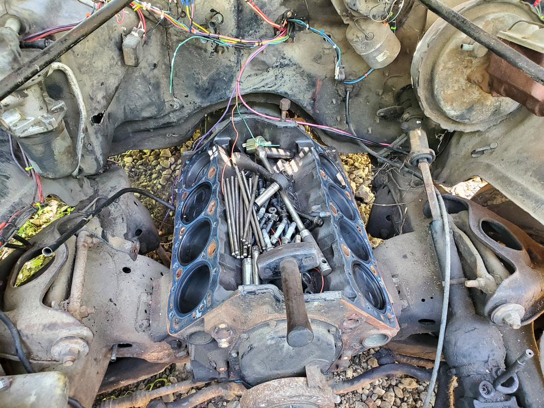
Engine block with heads removed. All the hardware in the lifter valley will be removed and placed in a bucket with the rockers for safe keeping.
Once the heads are bolted down I can move on and install the intake manifold and exhaust as planned, along with the accessories and their brackets. Just getting the right heads in place will allow me to move forward a long ways towards getting this engine complete and even ready for a test start if I so desired. I do have a distributor ready for use and the electrical system is already done so it won't really take much to make this engine ready to run, even for a brief moment.
Moving along with some routine stuff, we brought home another load of gravel, destined for the chicken yard. As stated before, I came full circle, spreading gravel back where I first started spreading the gravel. Areas of the yard have become rolled over with fresh dirt/mud or have retained water from runoff from uphill. All of this area needed to be covered up in order to help absorb and allow any water to dissipate otherwise it could allow more areas to get sloppy during wet cycles. Since I already started spreading gravel from the last load to cover the worst areas, I picked up where I left off, while also taking time to connect the patches that I had already started. Hopefully it won't take too many loads of gravel to get the yard covered up enough that I could move on to the back yard area, which is my biggest job yet, due to the size and how sloppy the grounds get when it gets extra wet. Those areas need to be able to hold the weight of a vehicle, no matter what the conditions otherwise.
Getting a more complete covering of the chicken yard grounds with more gravel.
Another little side thing that we managed to take care of as well was getting the Mercedes back to its owner. After having to go back under the car again to fix another one of the hoses that showed itself as a leaker when the car was actually running, and tightening up another hose with a better worm clamp, I got the car straight where it was safe to run and drive without the risk of starting an inferno underneath. It was nice to get the car back because 1: I completed the job and got the car back to its owner, and 2: I cleared some space in the compound by removing a vehicle. With the Benz gone, the next thing is to finish up the DOB. I still have to run the truck and test drive it to make sure all is good as far as brakes, engine tune and other functionality before we can take that vehicle back to its owner as well. Once that's done I can fully clear the side path to open the area up as well as get another vehicle out of our hands. 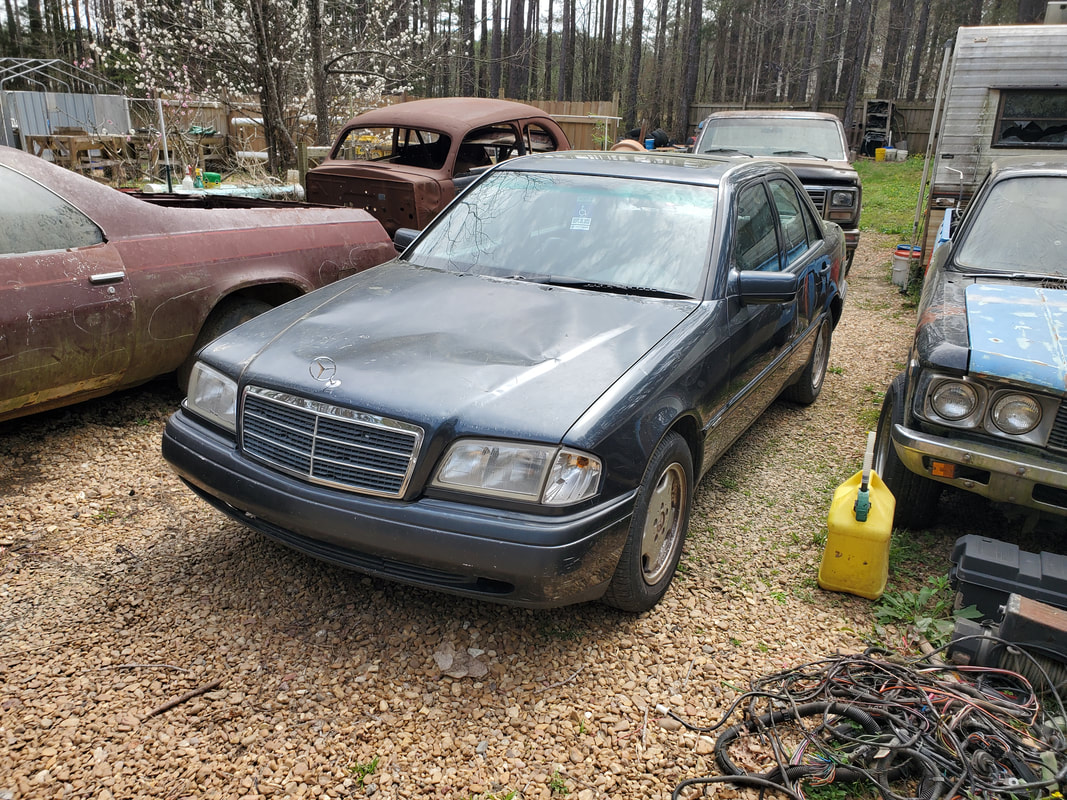
The Benz before taking it back to its owner, happy to have this project done and out of our hands.
The next thing that I took on was the construction of another drum raised bed. Since I had a couple plastic drums left over after setting four of the six drums out for the 65 Mustang truck frame swap, I went ahead and got enough wood to allow me to build one double drum raised bed. Going off the same design as the very last bed I made last season, I set out to start the construction, with the intent of placing the bed next to the compost bin. 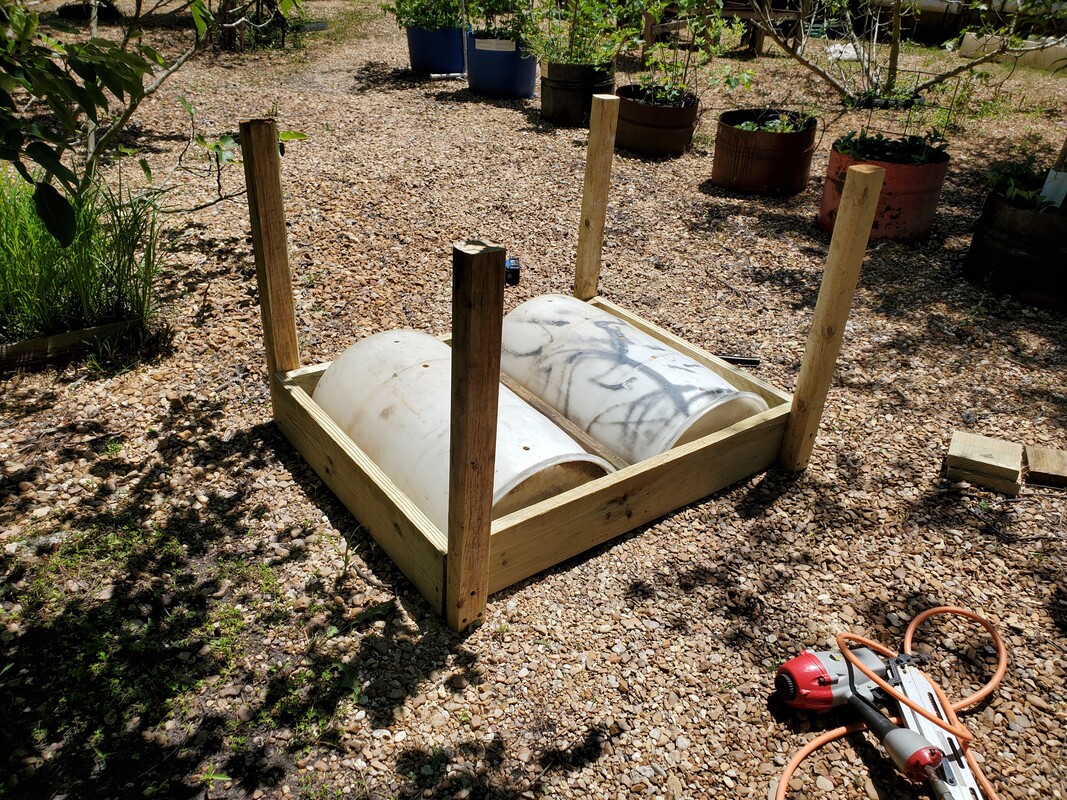
The raised bed after securing the boards together and attaching the landscape timber legs.
There's still a spot alongside one of the other beds in a set of three beds in the middle of the garden, near the Kennel Greenhouse. A fourth spot remains open, which I could've placed this newest bed there but instead I placed it by the compost bin. My bigger plan is to duplicate this raised bed design and have several of them set up side by side along the eastern fence line, all the way to the one fruit tree planter at the northeast corner of the garden. By setting the beds up in this manner it makes it easier to be able to set up the watering line and the taps for the micro irrigation system that will feed the sprayers that would be installed in all of the drum planters. 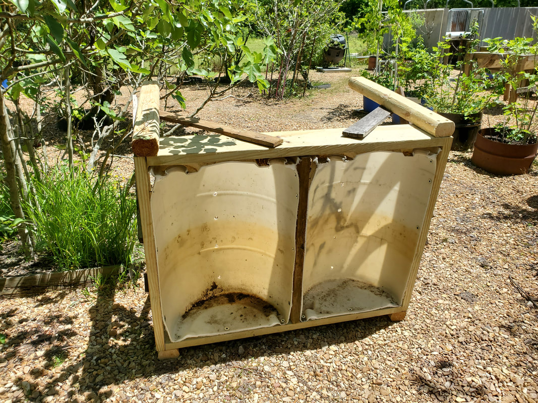
The raised bed with the leg braces attached and holes drilled in bottoms of drums.
Of course to make all these raised beds, I'll need plenty more drums, not to mention plenty of lumber and other materials to construct these beds. I can't even imagine how much dirt will be needed to fill all these beds when I do get to where I've filled all the space in the garden with raised beds, minus any hydroponic systems. With this large number of beds, we'll have a large growing capacity that will provide us with more veggies than we can imagine. 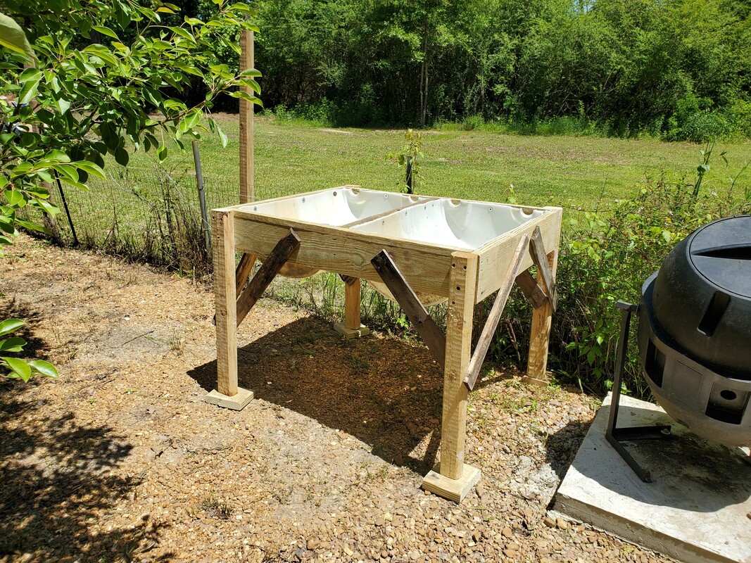
The raised bed set up in its new home, with the legs propped on boards to keep the bottoms of the legs off the moist ground.
This basic design allows me to get a fixed number of boards that allow for a low amount of waste when the project is completed. Of course, any scrap wood is set aside for use as scrap firewood later on. The brace boards that I used on the raised beds are actually salvaged pallet boards so these boards can be acquired for free any time I manage to get my hands on old pallets, which is not that difficult. Other than the pallet boards, all I need to build a single raised bed are two 8' landscape timbers, and two 2x8x8 pressure treated boards. The waste from the 2x8 boards is cut up into fourths to use as feet to set under the legs of the raised bed so they won't rot as fast from constant contact with the moist ground. At least with this bed, we're off to a start towards getting the garden set up like we really wanted.
|
