|
With the electrical system done for all intents, the next step on the Elco is installing all the interior pieces that I have. There's a few pieces that are too boogered up to be reused but for all intents I have everything to get the interior "whole", minus a pair of seats and a carpet. I stared off with the rear pillars, or whatever the proper term is for the posts running up the sides of the rear window to the roof. Each side has two pieces, covering the whole span from the floor up to the roof. There was a pair of smaller speakers that were hidden by these panels but since I don't have any duplicate speakers to mount in these spots, I had to mount the speakers on the back panel the way I did. The interior trim pieces will just go in their respective spots to cover up the seams where the cab sheet metal was spot welded together. 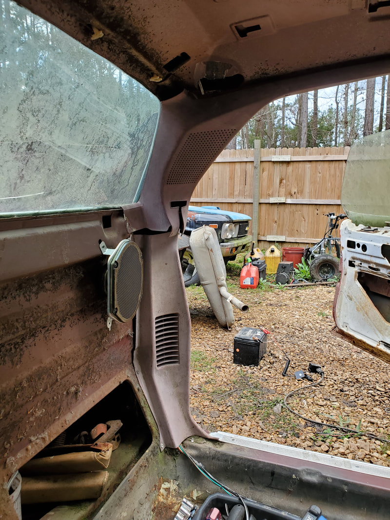 Driver's side rear pillar trim panels installed. Top piece covers up seat belt hardware and it covers what would've been the left speaker if one was installed in place of the old units. 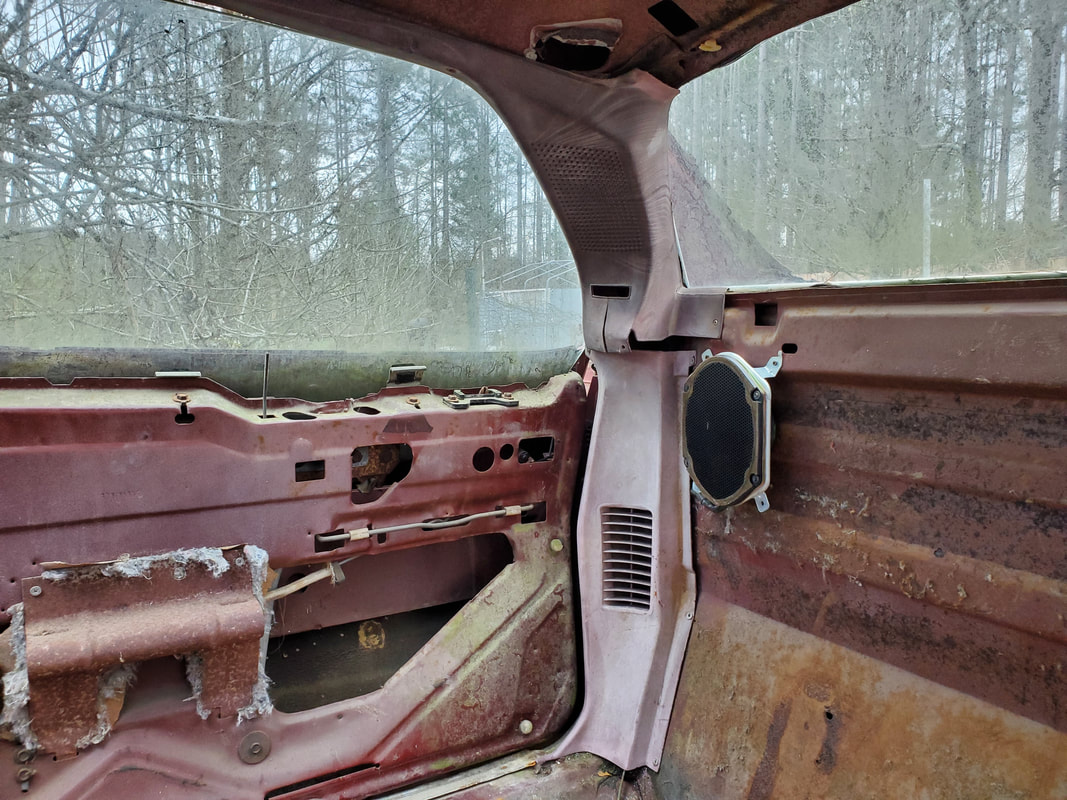 Same goes for the right side panels. Another couple of trim pieces that were overlooked were these small trim pieces that go at the top of the A-pillars and connect to the tips of the rear pillar trim pieces, completely covering the seams of the sheet metal joints of the cab. These pieces fit together with the other pieces and are secured with screws to hold the whole works together, completing the window/door trim. 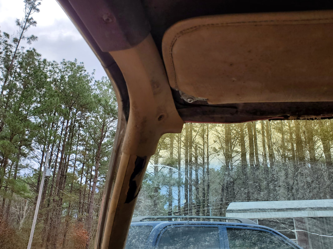 Driver's side A-pillar trim piece mounted and completing the whole window/door trim set. 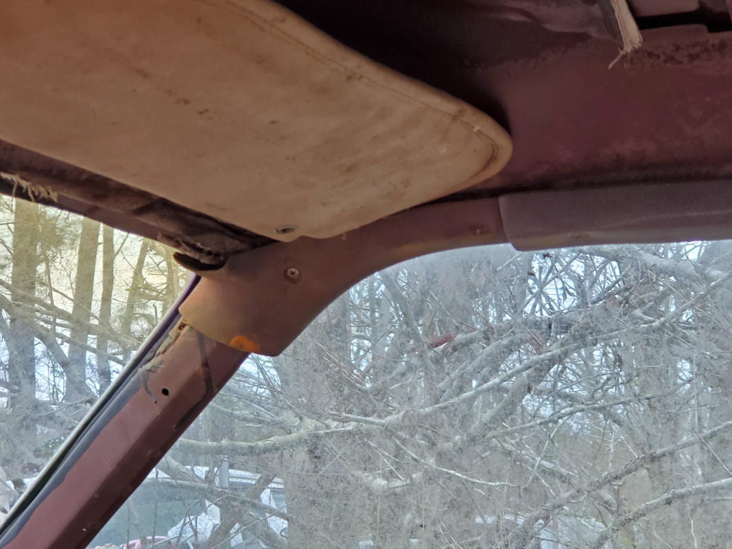 As well as the passenger side trim... With the window trim pieces in, next are the door panels. These also come in a two piece set, with the bottom piece being straight plastic and the top piece being a padded panel with particle board/cardboard backing. Both of these would normally be snapped in place with snap pegs, with the bottom piece using extra screws to hold the top of the bottom panel tightly to the door. Even though I had all the plastic pegs that held the panels in, due to age, some of them were dry rotted enough that they needed to be replaced. Luckily, I had many extras in the storage trailer so this wasn't a problem. Installing these panels was pretty straightforward, even adding the screws to hold the tops of these panels as stated before. 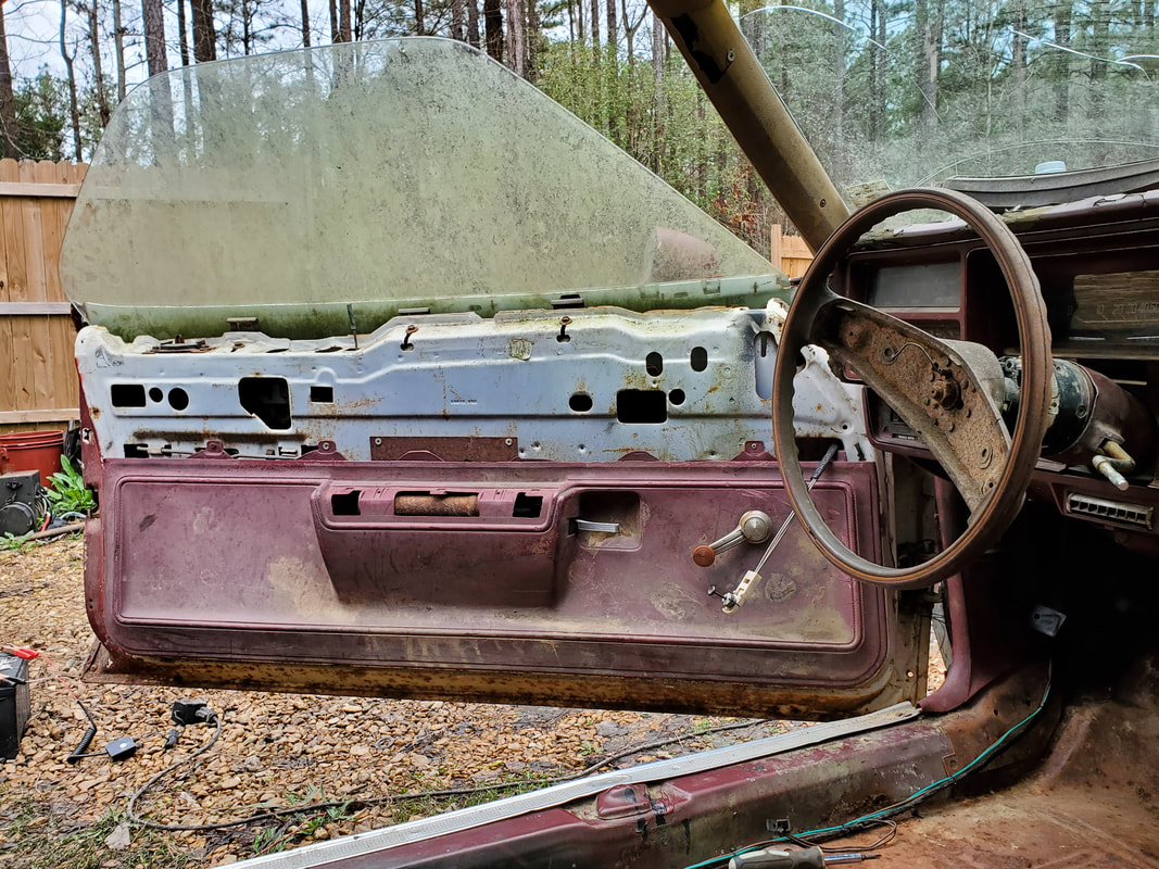 Bottom half door panel installed on driver's side. Note tabs along the top of panel with screws holding them to the door shell. 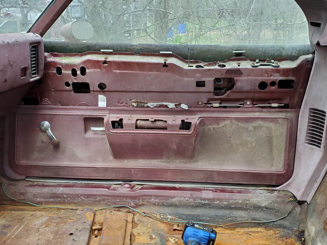 Passenger side bottom door panel in place the same way. Note the window crank also installed. Next are the top halves of the door panel set. These would be more problematic due to the fact the particle board backing was degraded to the point that there was no chance of holding any kind of pegs to secure the panels to the door. Other than the decent condition material of the padding, these panels are trash. Because of this, it doesn't really matter what I do to make these panels work. In this case, drilling holes through the padding to secure the panels to the doors with fender washers and sheet metal screws would be a fair option. I drilled three holes on the passenger panel, one at the front and back bottom corners and one in the middle. The top of the panel is made to hook onto the top of the door shell so it would be secured at the top with no further assistance from fasteners. With the right panel in place, I moved on to the driver's side panel. This panel was more degraded than the other, so I ended up having to put two more screws in, making a total of five screws/washers along the bottom of the top door panel to hold it in place. Even with this many screws, the panel is still shitty along the front bottom corner. It will have to do though, for now. To keep things even, I added two more screws to the passenger side even though it wasn't needed. 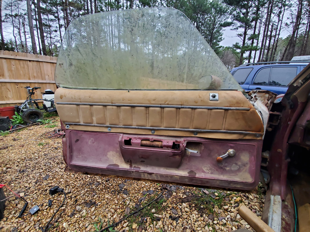 Driver's side top panel secured with five screws and washers along the bottom of the panel. Note how distorted the panel is on the front bottom corner of the panel. 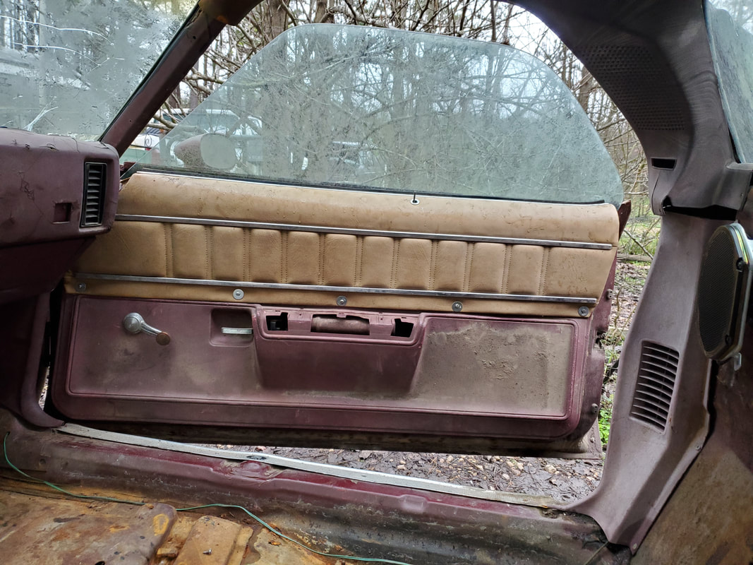 Passenger side panel with five screws (even though three were enough). Lastly, are the armrests. Just like the top half door panels, these were degraded underneath as well. The metal frames that make up the body of the armrests were rusted badly enough that I couldn't even secure them with screws properly as they were intended to be through the bottom door panels. Again, since these pieces are trash, it really wouldn't matter what I do to these pieces to make them work. That means, more screws and washers! I drilled two holes through the padding, down through where the screw holes in the metal were. I then drilled two holes through the metal brace behind the screw holes in the bottom panel. I then took some 3 1/2" deck screws and inserted them through the tops of the pads, through the old screw holes, then down through the new holes drilled in the metal brace, tightening the screws back and forth to draw the arm rests down evenly onto the metal brace and on top of the bottom door panel. The pictures obviously show how the armrests sit on the bottom door panel. 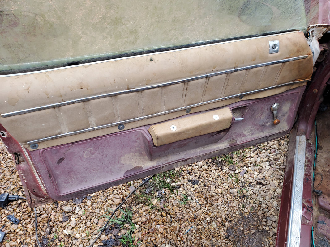 Armrest mounted on driver's side with deck screws and washers through the set of holes drilled as described. 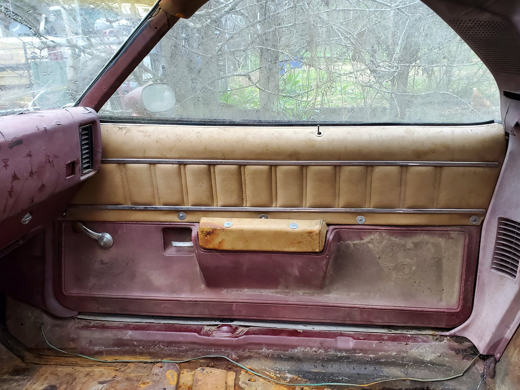 Same goes for the passenger side armrest. With the armrests mounted solidly, that pretty much completes the interior panel reconstruction. Even though there's screws and washers all over these pieces holding things together, everything is placed in an even enough manner to make it look somewhat normal, like it actually belongs. At least until I somehow manage to find reproduction pieces to replace these, this bootleg setup will have to do. I may try to do something to make things look a little better, like put some kind of rubberized paint or something over the washers and screws, maybe even use vinyl paint on the material, something to at least make things look a little better.
0 Comments
After spending so much time on the rewiring on the Elco and successfully testing the systems out, it was time to finally wrap up everything so I can move on to other things around the homestead. With all of the wires that were routed through the firewall, there's the risk that a wire could get chafed enough to expose the conductor to where it can short. If that happens, its 4th of July. We don't need to burn a car to the ground over a little mishap like that. Since I never managed to hunt down grommets made for routing wires through holes in sheet metal, as our namesake states, I improvised. For the smaller hole that I had to deal with, I took a small piece of this rubberized PVC sheeting that's used for lining showers before installation and cut slits in the piece. The purpose here is to roll the piece up around the bundle of wires and work the rolled material into the hole while still around the wires. The slits can then be opened up like tabs that I would then drill a hole through and into the sheet metal of the firewall to insert a sheet metal screw to hold the tab in the open position. Doing this will keep the rolled PVC sheet in the hole and around the bundle of wires. 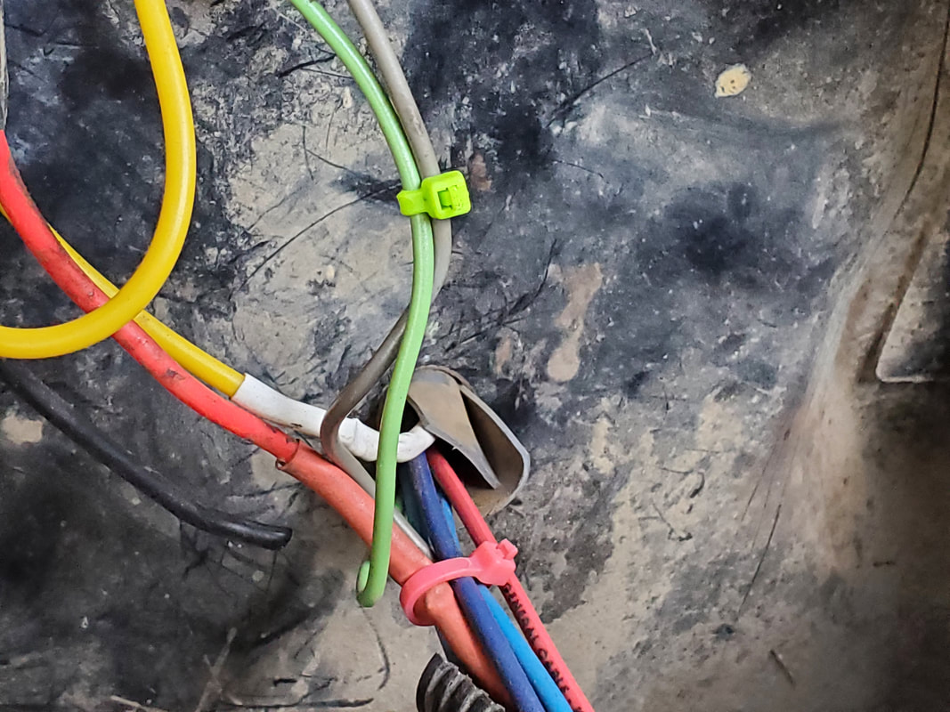 Rolled up PVC sheet piece around wire bundle and inserted into hole in firewall. Note the slits creating tabs on the roll. 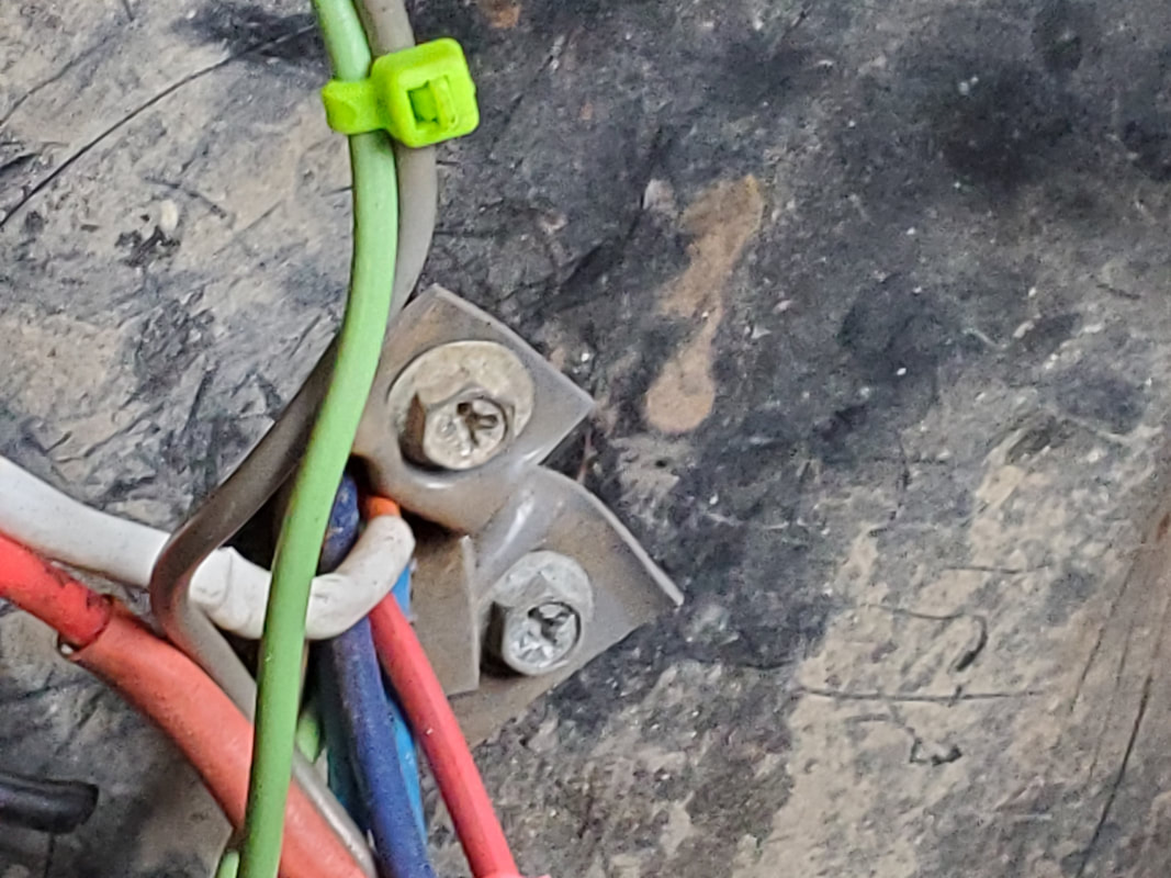 Closeup of tabs secured with screws to holes in firewall. For the other hole in the firewall that is kind of large due to it having the old bushing that held the old wire harness, I had plenty more room to work with. Instead of using more of the PVC sheet for this hole my next option was to use a piece of radiator hose. In the same way as I did with the PVC sheet, I slit the hose the long way to allow me to wrap the hose around the wire bundle, then had several small slits that would create the tabs that would then be secured by screws to the firewall. At least now the wire bundles going through the firewall are protected from possible shorting on the edges of the holes in the sheet metal. 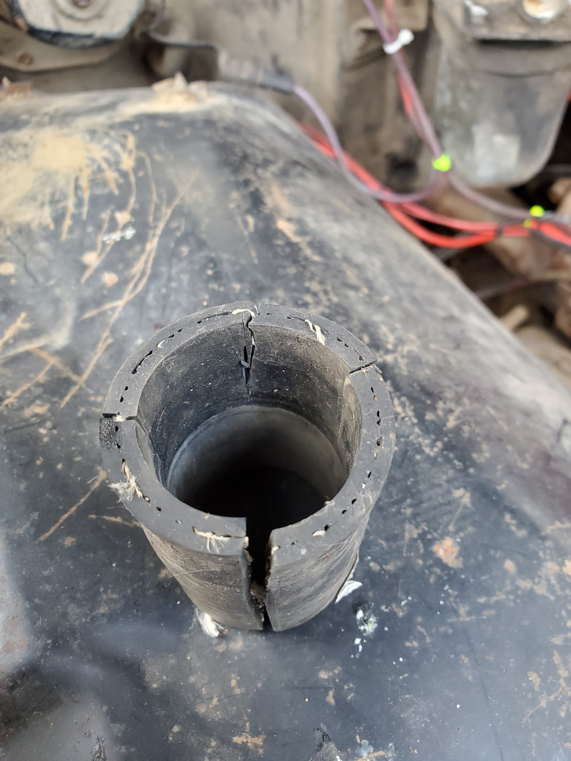 Piece of radiator hose cut in preparation for wrapping around wire bundle to create the grommet for the hole in the firewall. 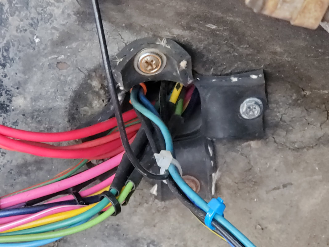 Tabs on hose secured with sheet metal screws to holes in firewall sheet metal. With that taken care of, I was able to divert my attention to something else that was important to me. Since we had planted several lettuce plants in several raised beds to have a little source of salad greens, I wanted to see how long I could keep these plants producing, even through the winter, especially since we haven't finished the greenhouse yet. With the bipolar weather that's been going on through this winter, I wanted to be ready for the turn arounds that typically have been occurring. One day it'll be 70-80 degrees, then a storm comes through or a cold front that caused a storm elsewhere will come through and make the weather pull back hard, causing temperatures to drop to 30-40 degrees, with the possibility of freezing. Because of this, I had to try and do something to give the plants a chance to survive. The easiest way of doing this was to take some painter's drop cloth plastic I had folded up and in storage in the trailer and spread that out over the raised beds. Since the plants are still small, laying the plastic over the beds won't damage the plants. Obviously since the plastic is super light, I had to put something down over the edges of the plastic to hold it down so any winds that come along won't blow the plastic away. The best thing I could muster up was several pieces of 4x4 wood that were left over from past projects. These pieces are small but still big enough that they can serve many purposes, from wheel chocks to simple weights, as is the case with our plastic for the raised beds. After laying the plastic down over the beds, I placed the wood down, holding everything down nicely. Hopefully this will be enough to give these plants a fighting chance to make it all the way through the winter and into the spring. 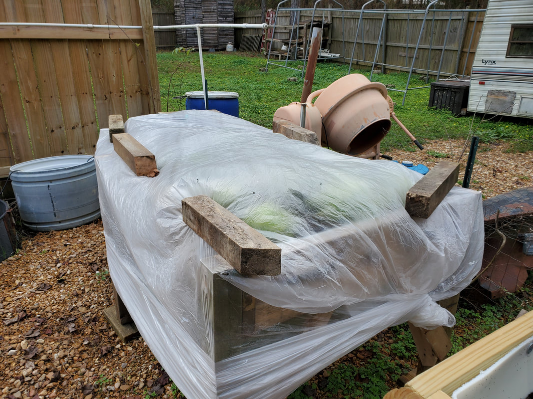 Dual drum half raised bed covered with large section of plastic partially tied off around the bottom and further secured with 4x4 blocks. 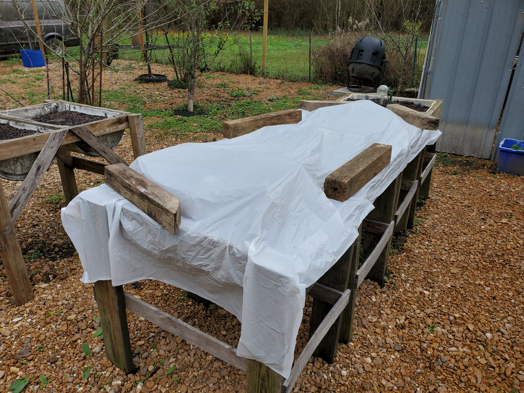 Row of raised beds covered in plastic and secured with 4x4 blocks. With that out of the way, I can move on to the next stage of the Elco project. I have most of the pieces of the Elco's interior, as far as the rear pillars going up around the rear window, to the door panels. Getting all these pieces installed will be one giant step forward to the completion of this car.
With only a couple things left to work on I was able to finally wrap up the electrical system rewiring on the Elco. The two things I still had to do was install the radio and the right turn signal housing, which I managed to get fixed due to its past accident damage. Starting with the turn signal housing, its only held in with a couple of sheet metal screws through clips on the housing. Of course this went quick, leaving the wiring of the socket to the wires that remained from the old setup. Once that was done it was on to the inside to install the radio.
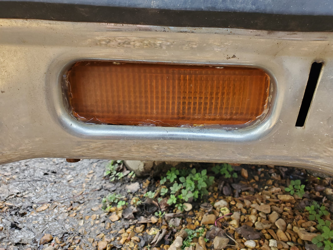
Newly repaired turn signal housing installed in spot behind hole in front bumper. From a distance you can't even tell anything was damaged.
The radio hookup is pretty straightforward. It needs two sources of power, a constant 12v and a switched 12v, plus up to four speakers. There's an extra line to feed automatic antennae or amplifiers where a signal turns these devices on from the radio when the unit is switched on. We're only hooking up two speakers and the two sources of power. The wire harness that comes with the radio makes this easy. I hooked up the speaker lines first. Then I took a twisted pair of red and yellow wire I had (due to the two power source lines being red and yellow), then hooked the yellow (constant 12v) to the same line feeding the 12v receptacles (since they're fed from a constant 12v line). The red line was extended along the wire bundle paths under the dash and over to the fuse box to be terminated there. From there was the actual mounting of the radio. 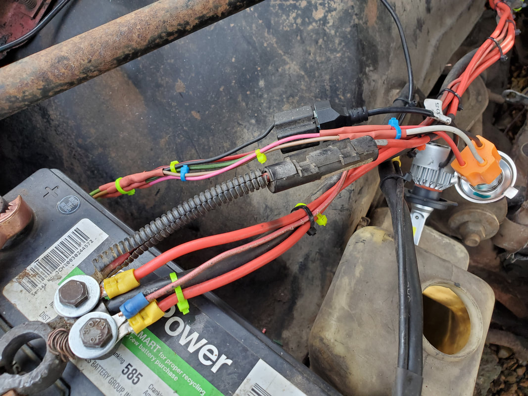
Inline fuse in place to supply power to the constant 12v power that feeds the 12v receptacles and interior lights, and now, the radio.

Low profile digital media player radio, a way better option than the traditional oversized CD and other similar radios installed in cars.
Even though I already had a radio mount shell installed in the dash frame, the mount that came with the radio was of a lower profile for the smaller bodied media player. The other problem was that the dash trim panel needed to be trimmed out more to accommodate the body of the radio. Even if I installed the newer mount in the dash frame, the radio wouldn't be able to fit through the trim panel. I had to relocate the radio mount to sit in the trim panel instead of the dash frame so the radio would be able to slide into the mount all the way. This involved some more trimming with the rotary tool to open up the opening on the trim panel so I can secure the mount within. 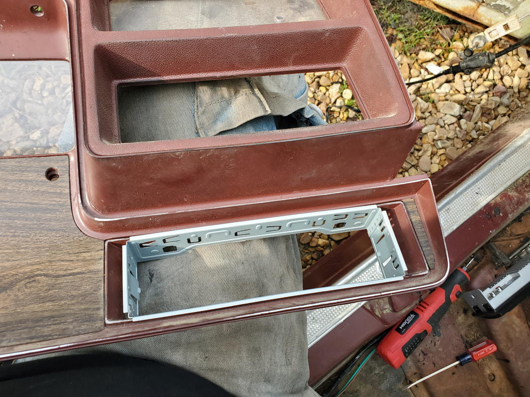
Dash trim panel after trimming hole wider to accommodate radio mount shell. I was able to mount the shell and bend the tabs where the unit will stay secured within the hole.
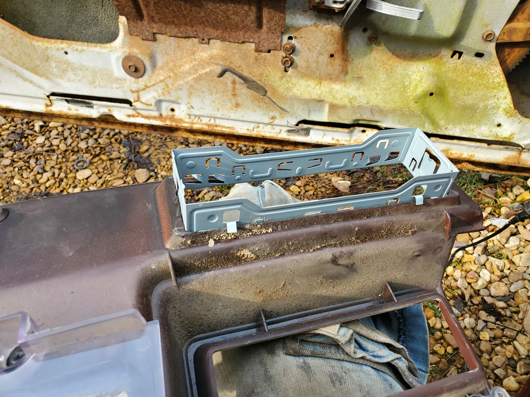
Backside of the dash trim panel showing the radio mount shell with the tabs bent to hold the piece in place.
With the radio mount shell in place and the dash trim panel mounted back in its place, I was able to mount the radio in its new home, plugging up the wire harness and antenna to the unit. A preliminary test showed that the radio came on with the key just fine and played plenty loud for the confines of the cab of the car, even with just the two speakers. 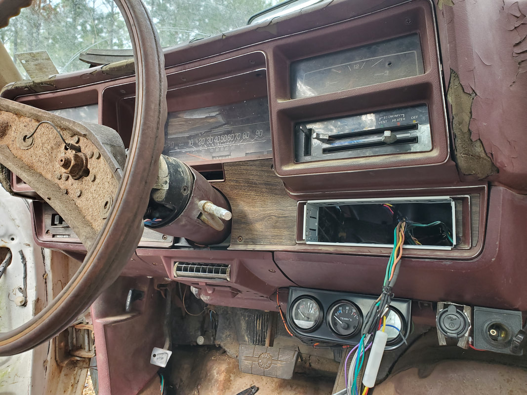
Dash panel mounted back up with wire harness for radio dangling out, ready to plug up.
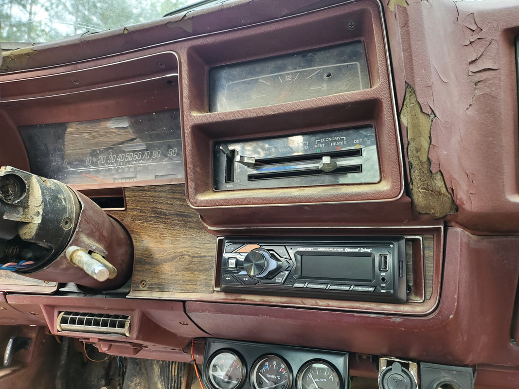
Radio mounted in hole, locked in place and ready to go. Despite some space issues with the radio mount, the overhanging lips of the radio body hide this enough to not make things as obvious.
With the radio in, the turn signal light in, and everything else in and plugged up, I was able to test out all the loads with the accessory switch as well as the constant power loads. Other than some items like a light bulb here or there a headlight socket or four there, all the loads came on as intended. With the electrical system done, I can now focus on installing all of the interior panels and getting that part of the car project out of the way, leading up to doing engine work afterward.
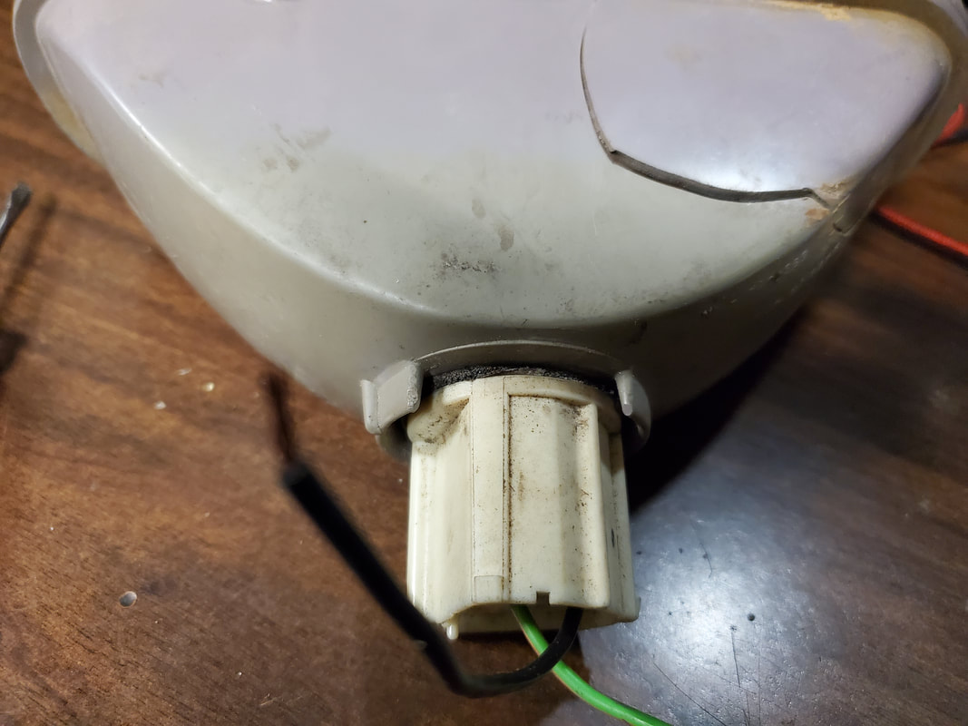
With so much being done on the electrical system of the Elco, there's only a few things left to work on. The main thing at this point is the repair of the right turn signal light housing, which was damaged when the car was in an accident a long time ago. The body is cracked and the amber lens is broken. The bulb socket is also missing on the right side so this will need to be replaced as well. I had some extra bulb sockets, mainly the extra ones that came with the rear bumper. Since those were replaced with the newer bulb sockets I had a few to choose from. I only needed a light socket that handles a single filament bulb since this is just for the turn signal. After some preliminary work I found that the hole on the light housing will need to be opened up slightly and the grooves opened up to accommodate the tabs on the light socket. This will be easily done with the rotary tool so that's no big deal, but the repair of the amber lens and the body crack are another story.
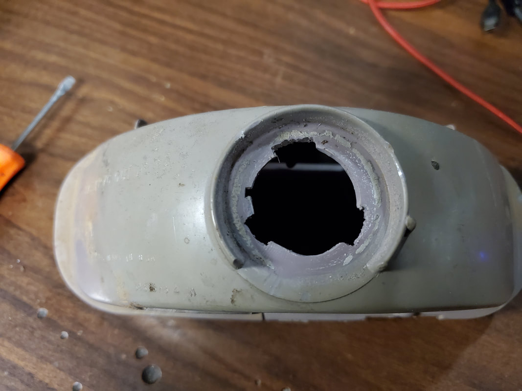
Light socket hole reamed out with rotary tool to accommodate different light socket that I just happened to have on hand.
Light socket twist locked into new hole.
New used light socket in place with sealing washer to keep water out.
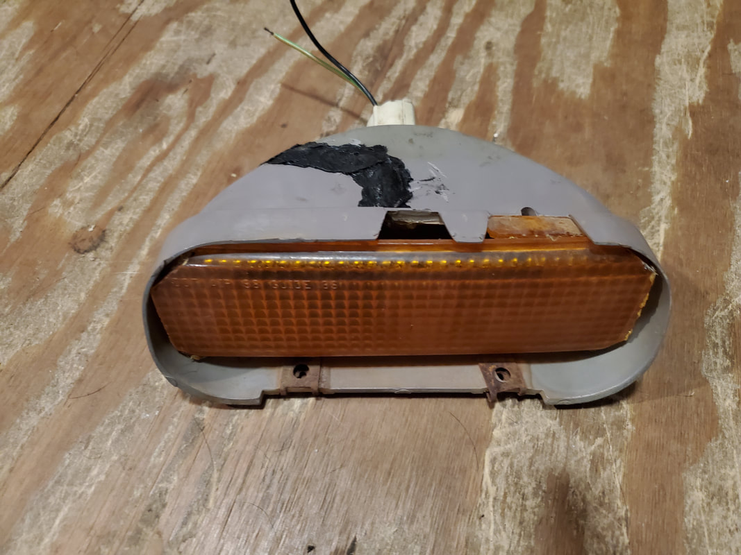
After the tool grinding to open up the hole for the new used replacement light socket, I was able to get the piece to twist lock in with no problem. There was a sealing ring made of foam rubber that helps seal the inside of the light housing from moisture intrusion, but it also helps lock down the light socket at the same time so this socket won't back out easily when the car's on the road bouncing around. With the light socket addressed the next move is fixing the crack on the light housing body. This was done using a plastic welder/hot iron kit. This consists of a hot iron that is like a soldering iron except the tip is a triangular shaped blade versus a needle point tip like that of a traditional soldering iron. The kit comes with these black rubbery plastic strips that are melted on the iron's tip and worked into the crack of the piece being fixed. At the same time you can also use the iron to melt the plastic on the piece you're repairing to further help fill in the crack you're trying to repair. 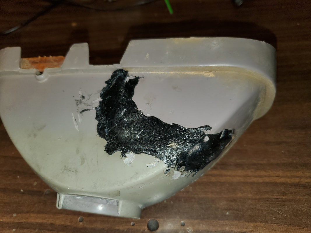
Melted plastic used with iron to fill cracks and essentially glue the damaged plastic together.
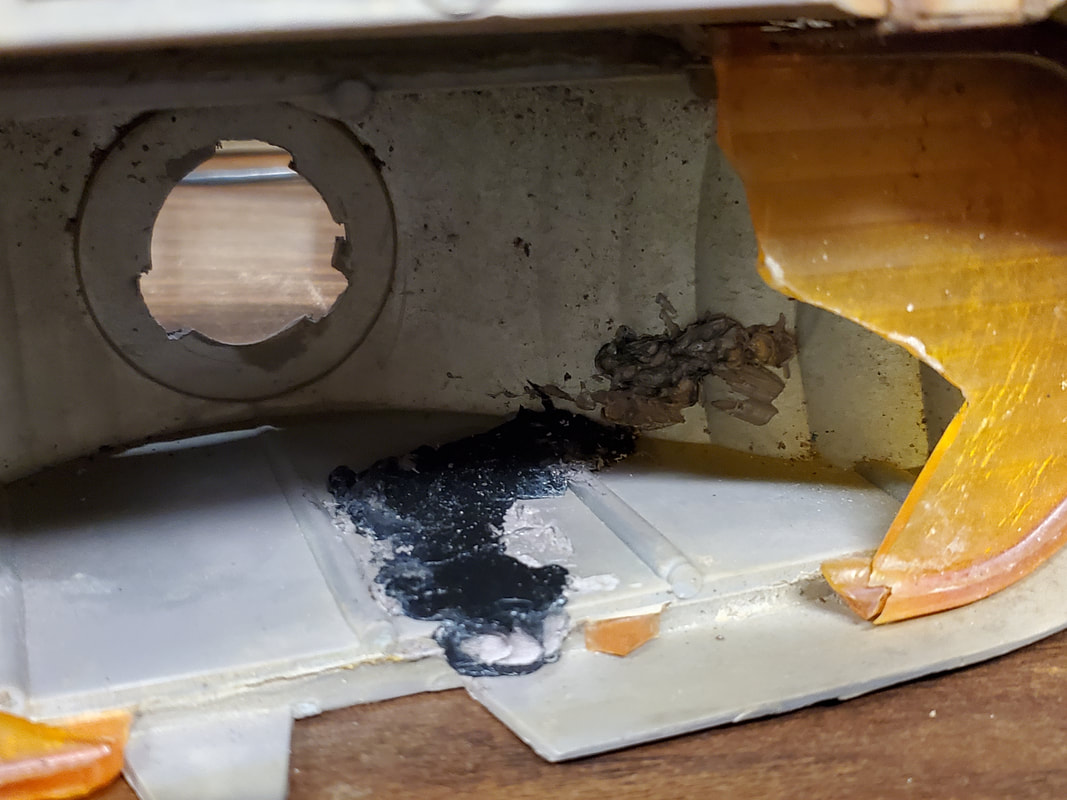
The same glue used on the inside to further glue the crack together on the housing.
The next thing is the amber lens. Since the old lens was glued in, it would be fair enough to assume that replacement lenses would not be available, I would have to get a whole housing to fix the problem in the traditional sense. Since we're not traditional, I decided to source the amber lens from another source, another vehicle's turn signal light. It happened that I had some extra turn signal lights for the S10, with an extra left light housing being available. I grabbed this, knowing that I still had a whole pair, if for some reason I had to replace turn signal lights on our S10 or another. My plan was to use the rotary tool with the cutting disc to cut a section of the amber lens out from the housing. 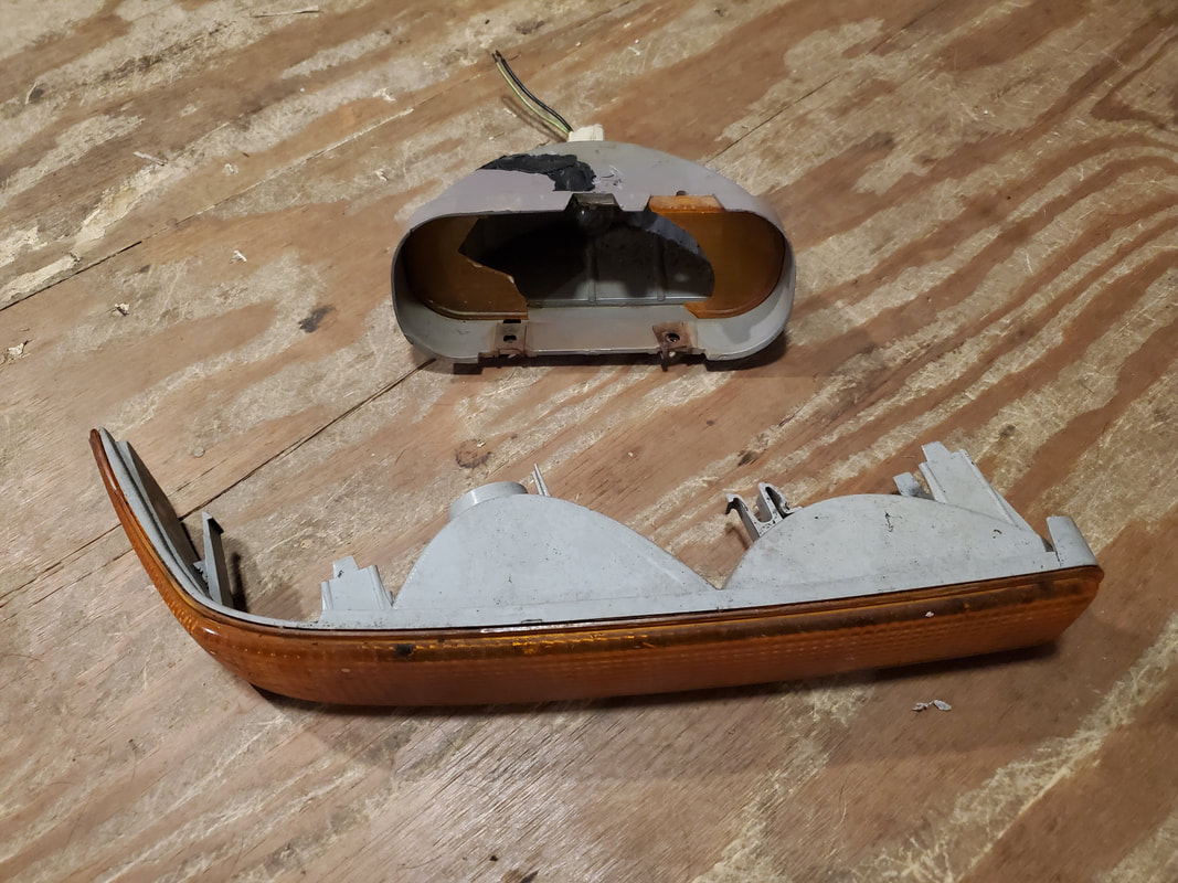
S10 signal light housing along with elco signal light housing.
I did some eyeballing measurements and used the tool to grind away a section of the lens to pull for the elco housing. Even with the whittling away I still didn't have the section of lens freed up, I would have to resort to more drastic measures.... 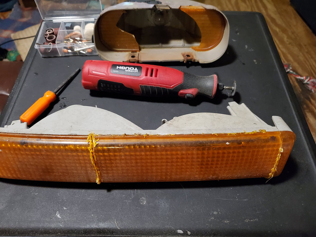
Section of amber lens cut to measure out the amount of lens needed to supply me with the lens replacement for the elco housing.
I ended up using the reciprocating saw with a fine tooth blade to chop the very end of the light housing off, allowing me to then cut along the edge of the lens where it was glued to the housing body. After enough jarring and cutting the glue finally gave way allowing the rest of the cut out section of lens to pop free. This signal light housing's services are no longer needed. 
Lens piece cut free from S10 housing.
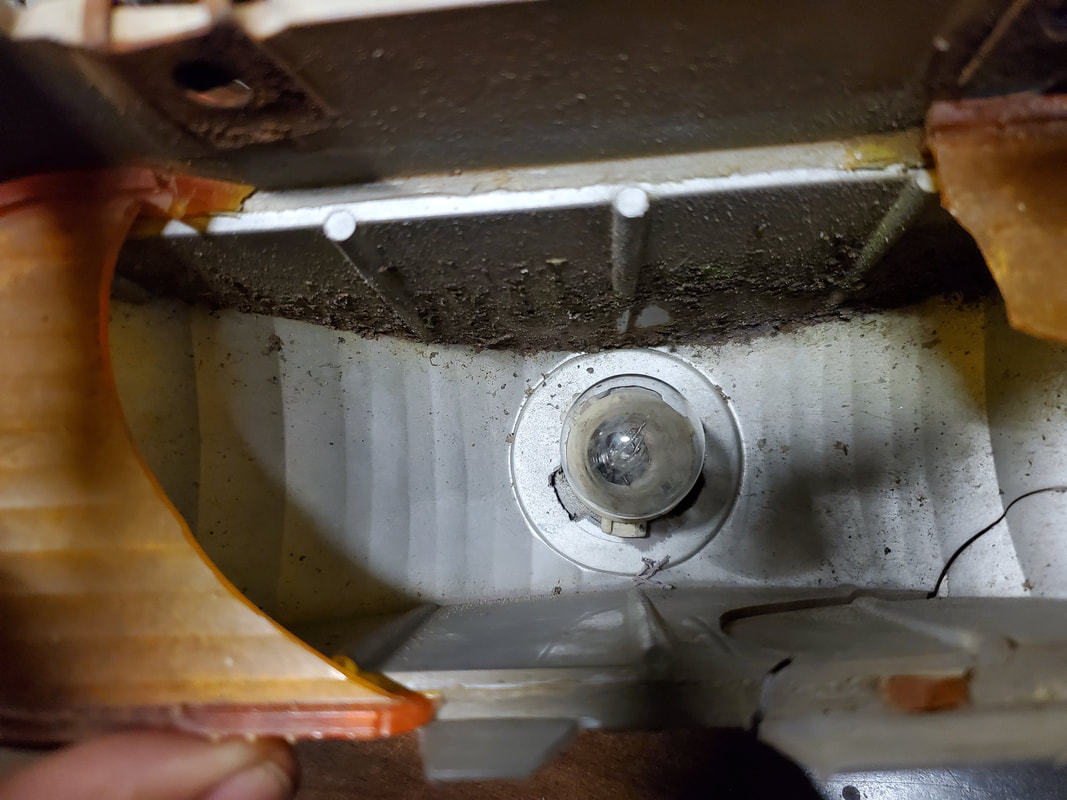
With the piece cut free I had to cut away the corners to allow the piece to fit into the elco light housing. After using the rotary tool to whittle away the corners and test fitting enough to confirm that the lens would fit, I then broke away the remainder of the broken lens in the elco light housing. 
Lens piece with corners trimmed to allow the piece to fit better into the elco light housing.
Test fitting the lens in the light housing.
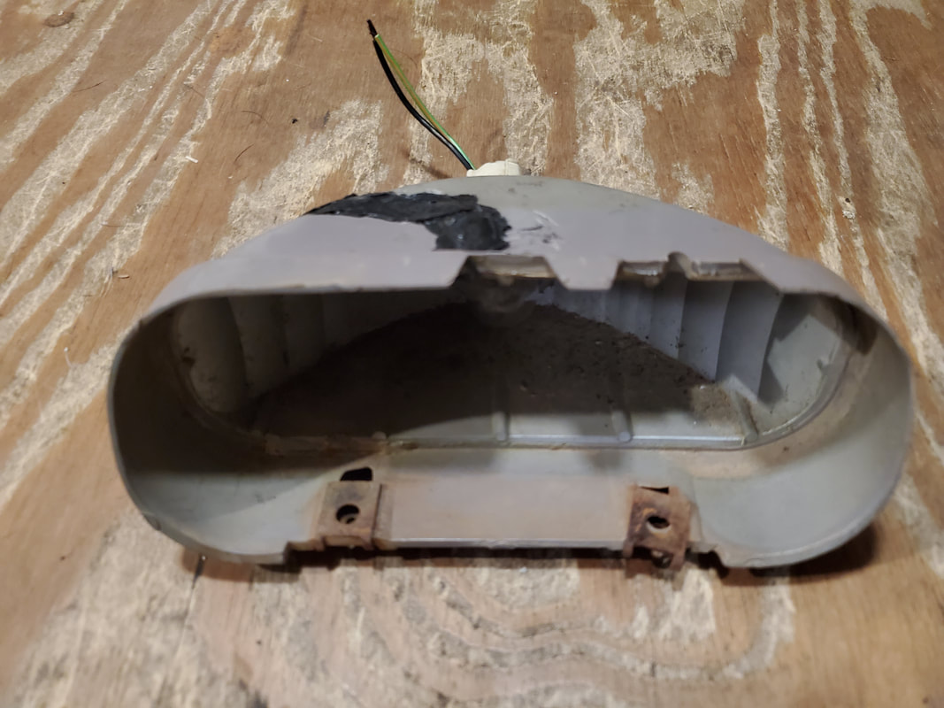
Remainder of the old broken lens removed from the Elco light housing.
With the old lens broken out and the new lens able to be fitted I heated up the glue gun to get ready to glue the lens in. Once in I applied a bead around the light housing edge, pressed the lens down then further applied glue around the outside of the lens to seal the piece in nicely. 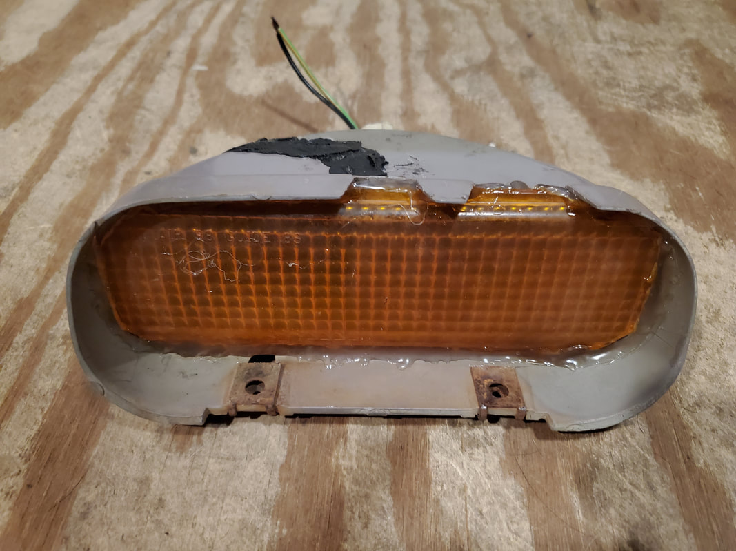
With the lens glued in I can now reinstall the housing as well as wire up the light socket so I can write off the turn signal system as completed. This little sub-project obviously saved me who knows what in the cost of a replacement light housing. The work on this item just shows why we are The Improvisation Center.
I'm finally starting to see the end in sight for the Elco electrical system rewiring. There were a couple of small items I wanted to take care of real quick before I can test things out. I still have to buy a few items but for right now I'm trying to get everything done that I can get done with what's available. The first thing was a small light that sits right over the rear view mirror, or at least where a rear view mirror would sit. This is one of those little lights one would use for reading road maps or some other item while in the car, or for illuminating the area under the dash and on the center console. This little fixture is held in place with two screws and is grounded to the chassis via the screws, with a single power line running along the top of the windshield and over to the driver's side A-pillar and down into the dash. 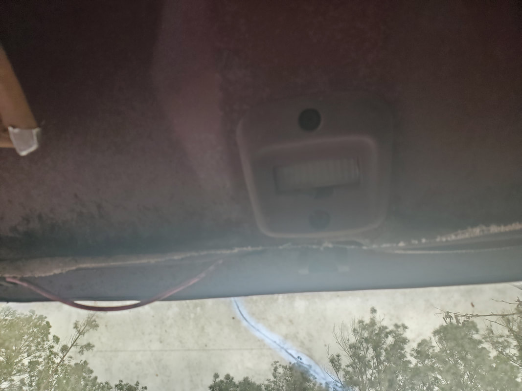 Reading light installed over rear view mirror area. Note power wire to left, running along top of windshield. Funny thing is I need the moldings that would cover the area over the windshield to help hold the wire up and hidden, along with the A-pillar molding/trim piece. I do have the A-pillar trim but it's pretty degraded, with the plastic being super brittle. I secured the piece with the one screw that it accommodated but drilled an extra hole to hold the trim piece down near the top of the A-pillar. If I had the trim piece to go over the top of the windshield, adding the extra screw wouldn't have been necessary but without it, is necessary to keep it from flopping around. Plus since the piece will need to be replaced, hopefully by a new aftermarket piece, I really don't care about poking another hole in this piece. 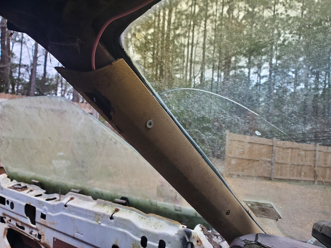 The next thing to address that I didn't really pay any attention to until after getting everything done is the horn. Of course this circuit will be very simple, being just a horn assembly and a switch. The main problem I ran into was where to mount the switch. Since the clock spring assembly is trashed in the steering column (along with the steering column body), using anything in the steering column is off the table. That leaves adding a switch to a spot on the dash. Since I didn't want to poke any holes in the dash trim panel, I decided to do something else. Since the vents for the HVAC system have been shortened, the vent assembly on the far left of the trim panel has no tube going to it. I decided to remove this vent assembly and replace it with a plain piece of sheet metal cut to fit and drill a hole in that to secure the horn switch. 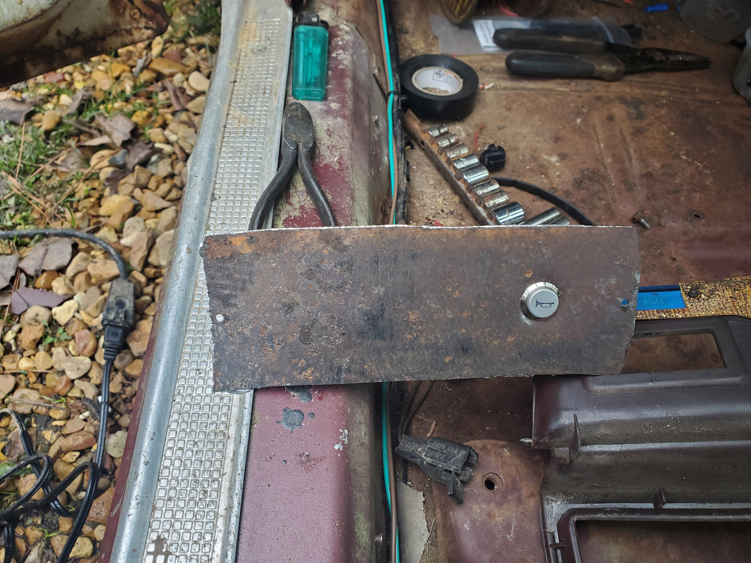 Sheet metal panel made to fit in dash trim panel with horn switch installed. I ground the rust off the piece of sheet metal and drilled the screw holes where they needed to be then drilled the hole for the switch using a step bit. The switch I had was actually the same switch that was used in the old Tracker and salvaged from it after it was crushed by a tree. This switch already had a few inches of wire hooked up to it so hooking up to the switch will be rather easy. I installed the panel in the open spot on the dash trim panel then ran two wires. One is coming from the fuse box, routed along the same path as the other wires to go into the switch then hooked up another length of wire to feed out through the firewall over to the driver's side where I will install the horn assembly, which is a bracket holding two horns, again salvaged from one of many cars we've stripped down over the last couple of years. To make things easier when it comes to removing the dash panel, I used a two conductor male/female plug set that will allow for the horn switch to be disconnected from the wiring so the panel can be removed with the switch still in place. This plug set is made to where you push the wires into the plug and spring-loaded metal terminals grab the ends of the wires, holding them in place. 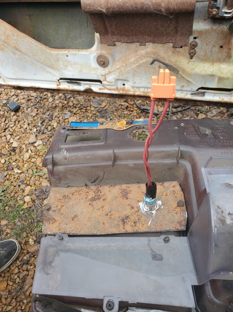 Back of panel with nut holding horn switch in place, also the male end of plug set plugged onto the wires from the switch. 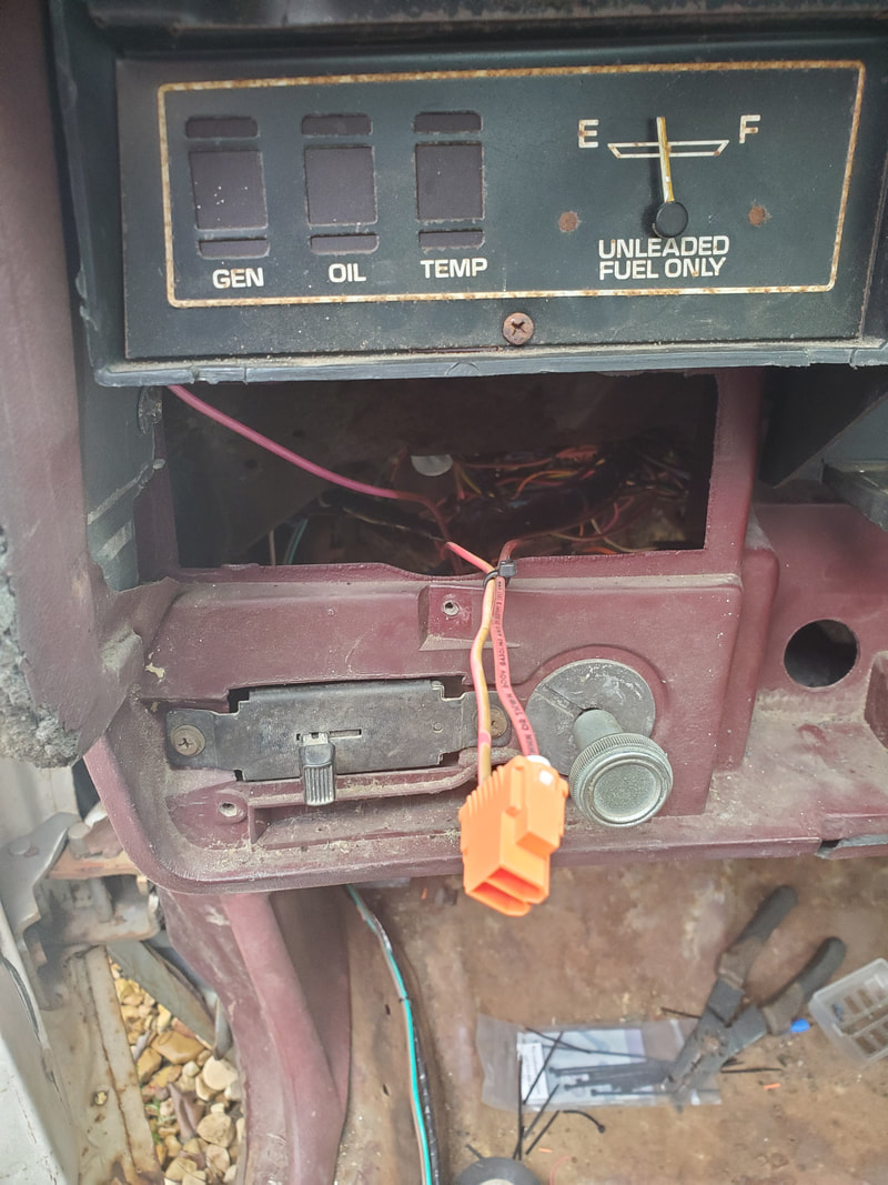 Female end of the plug set, hooked up to the wires going to their respective destinations under the dash. With the panel in place, the horn button is in a spot that makes it readily accessible without accidentally bumping into some other component when one needs to blow the horn in a hurry. It's in a spot that makes it visible enough to not have a delay in trying to see just where the switch is at. Plus, no extra holes had to be drilled in the dash panel. Removing the unused vent cleans the dash panel up and frees this space up for extra items to be used, such as this horn switch. Since the switch was installed off center, it opens up the possibility to add more switches for any other additional devices I may feel compelled to install at a future date. 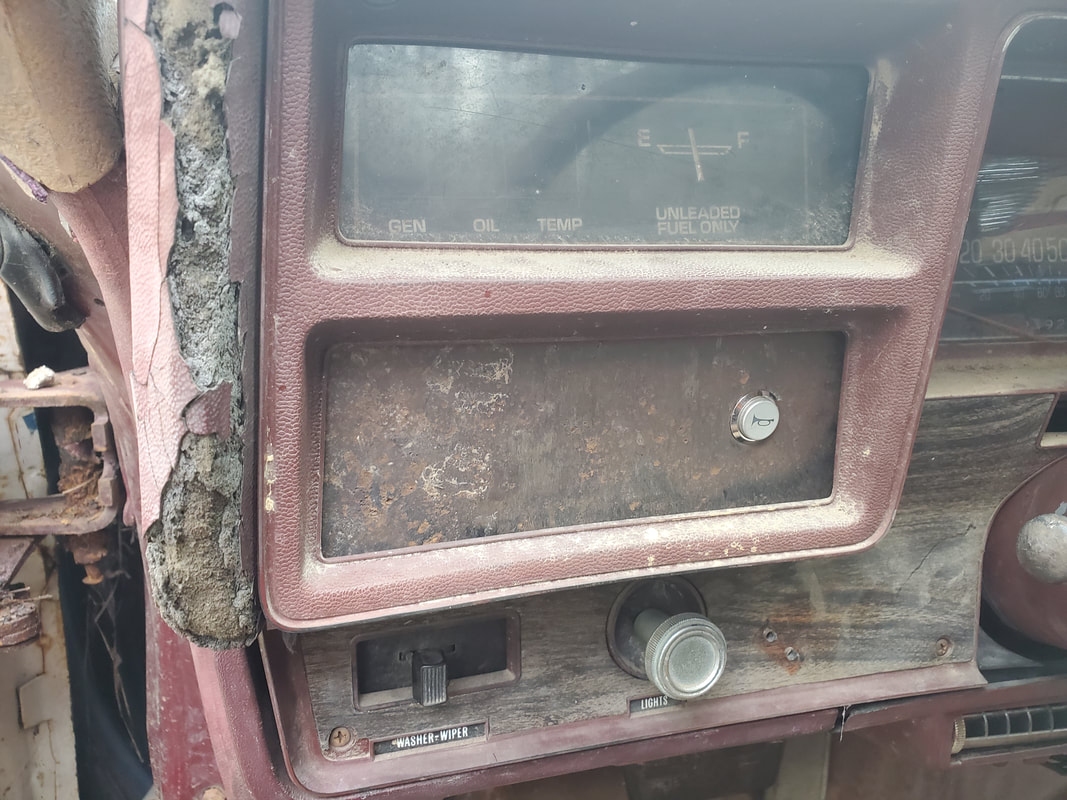 Horn switch and panel installed on the dash trim panel and panel installed back on dash frame. Note the amount of extra room available for extra switches or what not. With the horn assembly installed and the wires secured in the same snake that holds the wires for the headlight circuitry, that writes off the horn circuit. The horn gets power from an unused circuit on the fuse box which due to it being intermittent in its use, is acceptable for being hooked up on the fuse box versus on its own circuit with an inline fuse. 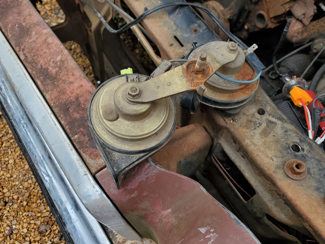 Our horn set, pulled from our storage trailer stock.  Horn assembly mounted with power wire plugged up. At this point there's only a few small items left to install before I can test everything out and sign off on the electrical system. One of those things is the radio. I'll have to pick one up and install the thing, but at least most of the work is done as far as the speaker wires being installed along with sources of constant 12v and switched 12v power. Once that's done I have to install some replacement bulbs in the two under dash interior lights I added to the mix to complement the dome light. I'll end up using LED bulbs since I'm always on a quest to replace every incandescent bulb with LED's. Lastly there is the matter of getting the right turn signal light housing addressed. I can probably repair the piece since it needs an amber lens to replace the broken lens plus I have to install another light socket since the one that was in the housing is long gone. I'll also have to repair a crack in the body, damage that was most likely done during that front end collision. Once we get those little things out of the way we can power things up.
Coming into the home stretch on the Elco rewiring job, I hooked up the few remaining components I felt were necessary to be hooked up, in addition to the last of the important loads-the taillights. Even though the taillights were already wired up as part of the brake light/turn signal/taillight circuitry earlier, I still had to wire up new light sockets to replace those that were all boogered up from age. But over to the other components I wanted to hook up first, before going to the taillights. I wanted to hook up a pair of externally mounted 12v receptacles under the dash next to the aftermarket gauge cluster. Since the 12v receptacle/cigarette lighter socket in the ash tray was questionable at best and unable to be disassembled, I decided to forego the whole thing and just install fresh pieces. Upon a quick examination of the two 12v receptacles I had I found that one of them had a partially melted terminal, that receptacle would be useless. That left just one, now what?
The next option was to install a dedicated 5v/USB receptacle in place of the bad 12v receptacle. This would provide the USB charging I would want anyway while keeping the 12v receptacle freed up for uses all the way up to plugging 12v devices. The twin USB charger that I had was a unit that is typically installed in a hole and secured with a large nut behind the hole, usually in the dash, making the device be more of a flush mounted piece. Since there wasn't a suitable spot to mount the socket on the dash, I had to come up with a makeshift external mount to hold the receptacle. 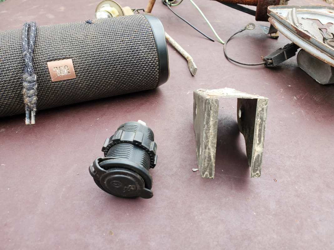
USB receptacle and wood frame bracket to be installed.
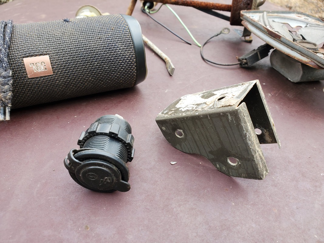
USB receptacle and wood frame bracket to be installed.
The solution, as with the turn signal switch, was to take a wood frame bracket from a stack of salvaged brackets and modify it to be used as a mount for the USB receptacle. The existing holes would allow me to mount the piece under the dash easily. All I had to do was whittle away the tabs on either side of the spot I would mount the USB receptacle in order to accommodate the round piece nicely with no real chance of moving. Using the angle grinder I got the piece prepped to install the receptacle. The next thing I had to do was drill the holes under the dash to mount the piece. After mounting the bracket under the dash, I put the receptacle in the mouth of the bracket. To clamp the receptacle in I took a long bolt with nut and using another pair of existing holes, inserted the bolt through both sides of the bracket, under the receptacle, using the nut to tighten the sides of the bracket around the receptacle to hold it in place tightly. 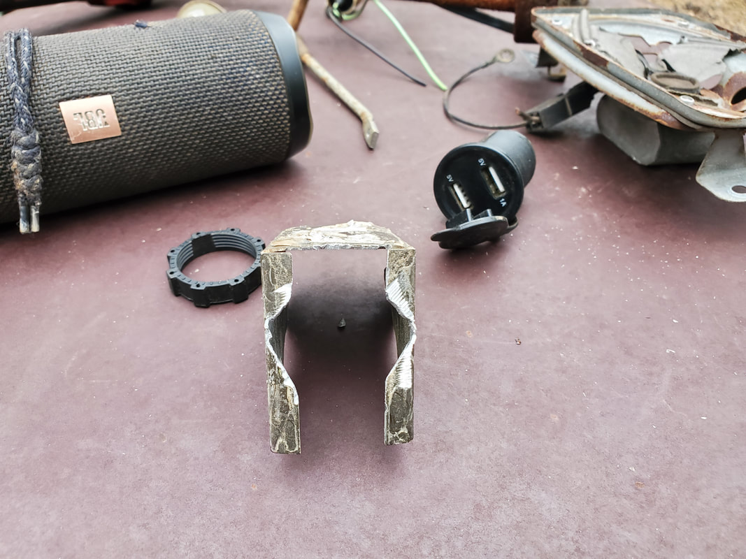
Wood frame bracket modified by cutting away some of the sides with an angle grinder to create a cavity to accommodate the USB receptacle.
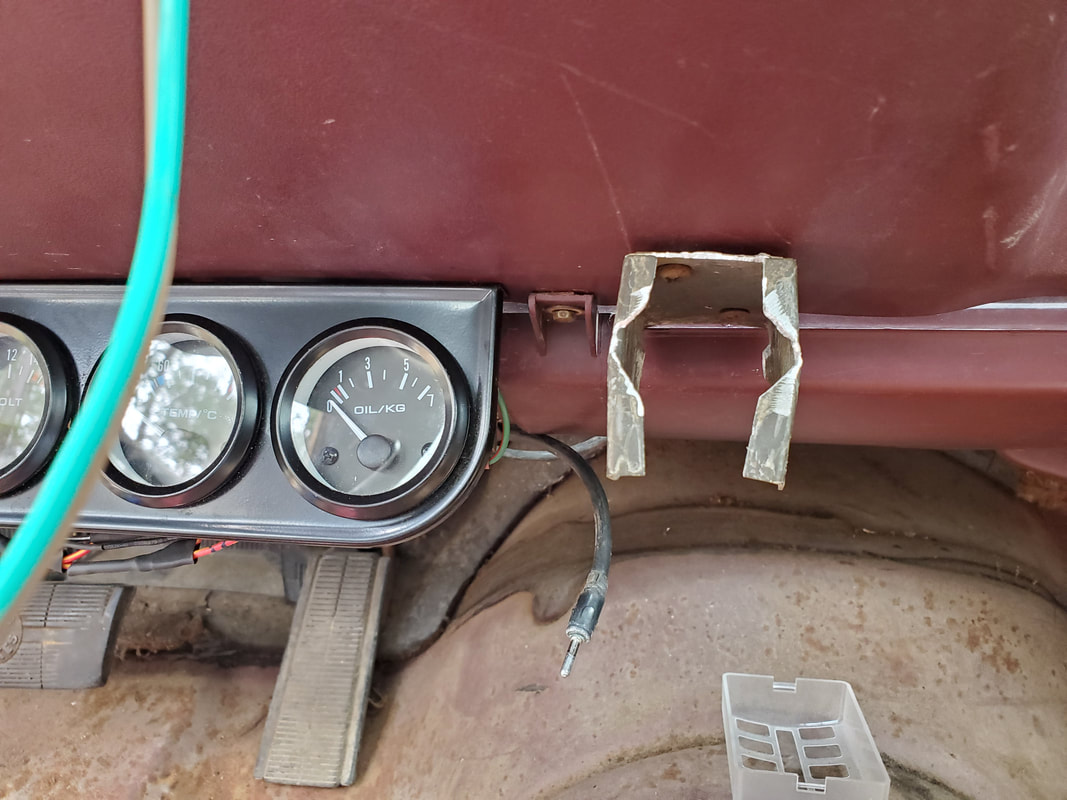
Modified wood frame bracket mounted next to gauge cluster.
With the bracket mounted in place I also mounted the regular 12v receptacle next to the USB receptacle bracket. I wired the two receptacles together with a shared ground and power line, routing the power wire out through the firewall and around the same path as the main power lines coming from the battery. I'll be hooking up an inline fuse at the battery to feed this power line that will supply power to the 12v receptacle (up to 15 amp) and the USB receptacle. At the same time I also took the time to remove the power line feeding the interior lights from the fuse box and splice it in to this same receptacle power line as well. Reason being that I would want the interior lights to come on when the accessory switch isn't activated, such as when I first enter the car. Same thing goes for the receptacles. Power may be needed at a time when it isn't necessary to run the car, like at a camp site or fishing hole or whatever. 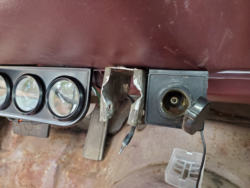
12v receptacle mounted on other side of wood frame bracket.
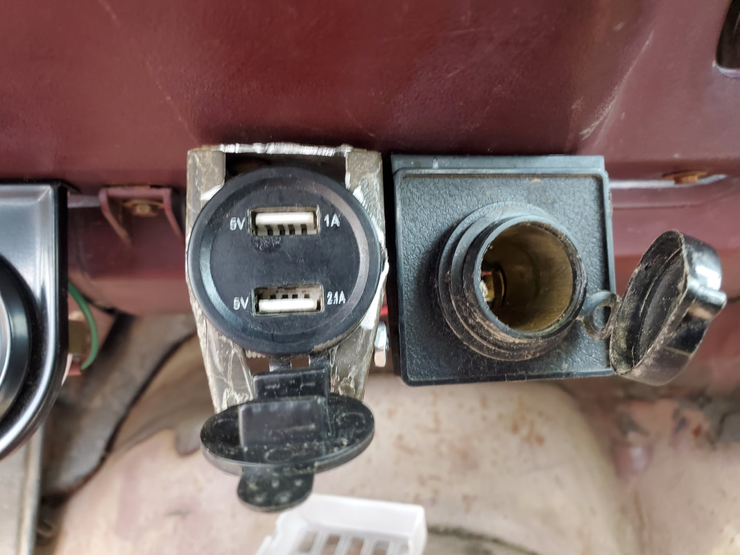
USB receptacle mounted in bracket.
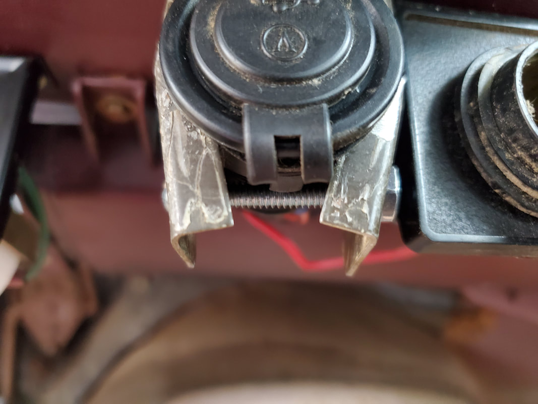
Closeup of USB receptacle in the wood frame bracket showing the nut and bolt used to clamp the bracket around the receptacle.
With the receptacles installed under the dash I turned my attention to the taillights. This went pretty fast and easy for the most part, with the only slow process being the testing of the terminals on the sockets to determine which lines fed the lower lumen filament of the dual filament bulb versus the brighter filament. This way I was able to determine which sides of the sockets would be hooked up to the taillights, which need only low lumen light, and the brake light which would need a brighter light. The turn signals were to be installed as a standalone light fixture so it was ok with wiring up both filaments together. I also used my battery rotary tool to whittle away some of the light socket on one of the taillight fixtures to accommodate one of the light sockets. The opposite side fixture was degraded enough with bits of the plastic having broken away that I was able to twist lock the socket in place with no problem. I had two different styles of sockets with the other style actually fitting in the old light sockets with no problem despite these sockets coming from early 2000's cars. 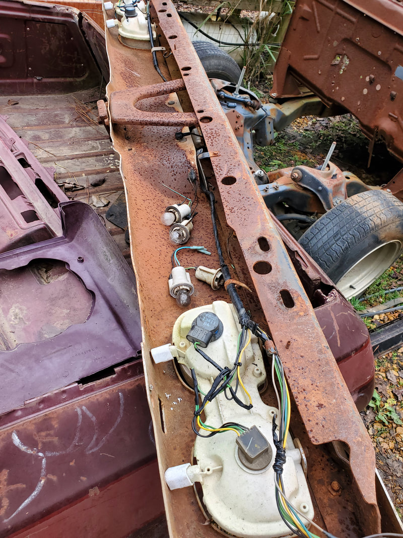
New used taillights installed in light sockets and wired into the bumper wire harness, ready for use.
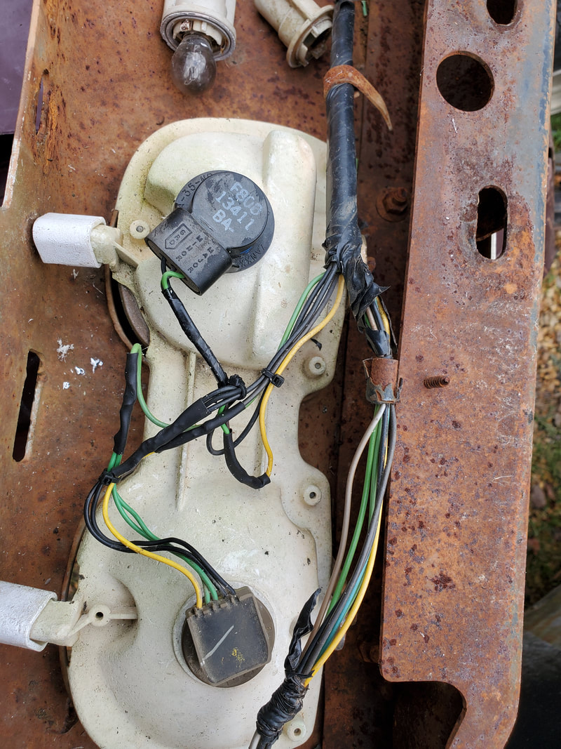
Closeup of light fixtures with newer light sockets twist locked in place. Note how there's two different styles of sockets.
With the new taillights hooked up to the bumper wire harness, I can now start making preparations to test out the loads on the car. On the headlights, since I don't have the square light sockets for accommodating H4 bulbs, I had to resort to taking some spare H4 bulbs and plugging them into the headlight sockets in order to be able to test them outside of their mounts. Other than the radio (which still needs to be purchased and installed) and the right front turn signal light and some other bulbs that will need replacing, everything is pretty much ready for testing.
Today was a day that a good amount of stuff was done on the Elco regarding the wiring. I had already gotten many circuits staged, getting the wires run to the termination points I wanted them to be while I had to source the load components to put on the wires. Things like the dome light, speakers, and turn signal switch were what was on the menu for today. I started off with the dome light. I had already started getting the two door switches situated, getting the side panels reinstalled after getting the wires where I wanted them, grounds included. We went to the junkyard to source some parts, one of them being the dome light. I found the same dome light that I used in the 69 Mustang, AKA the Rustang. I installed a dome light in that car a year ago using a unit from a late model Grand Prix. These lights have a mount on them holding rare earth magnets, making the whole fixture stick to the ceiling like glue. Part of the installation of this dome light involved running wire. Even though there was already a pair of wires from the old dome light down the side of the cab over to the front, I still had to run wires for the door switches. 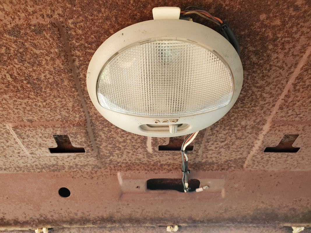 Late model Grand Prix dome light from junkyard car, used on the Elco. While it was no big deal to wire up the dome light, I still wanted to install the two fixtures I pulled from under the dash. I don't remember exactly where they were but I found suitable spots for both fixtures. Using LED bulbs these fixtures should light up the underside in the cab. I had to run the wires from these fixtures over to the junction point for everything, near the fuse box. I did run the wire from the passenger side door switch and under dash light over to connect to the other door switch and light, then routed those wires to power as intended with the circuit. After securing the wires with some of the already established wiring I can now say the interior light system is ready to roll. 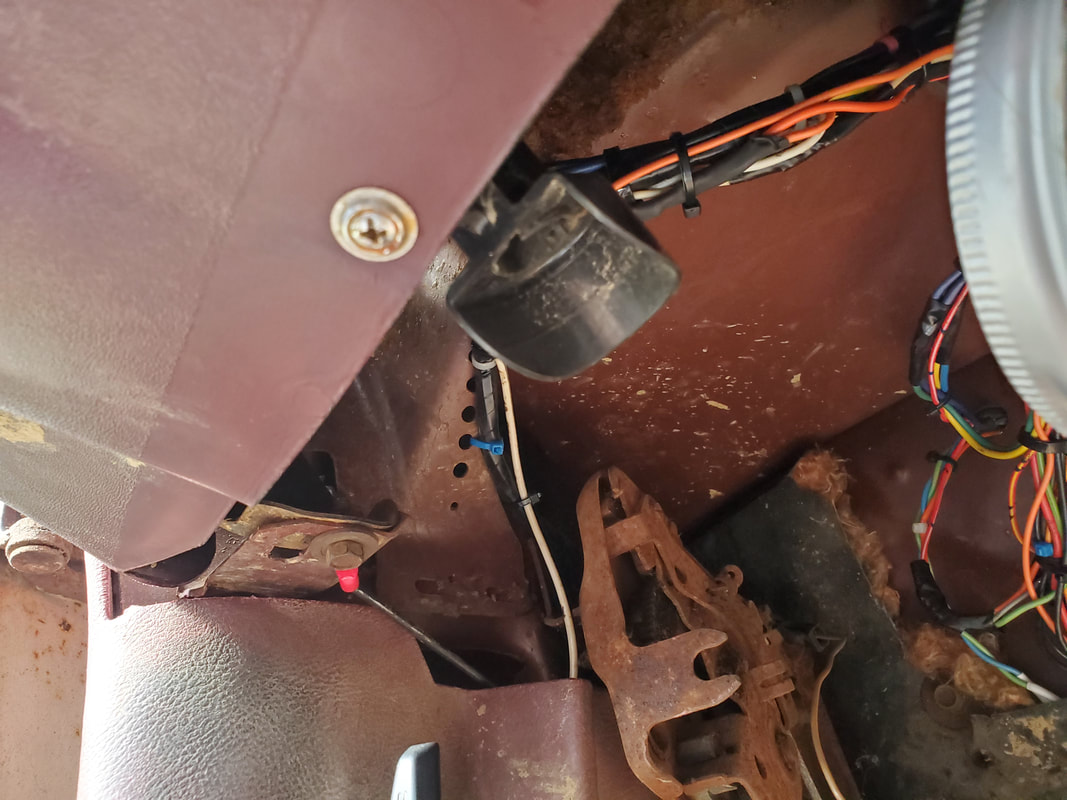 Driver's side under dash light fixture in place and wired up. 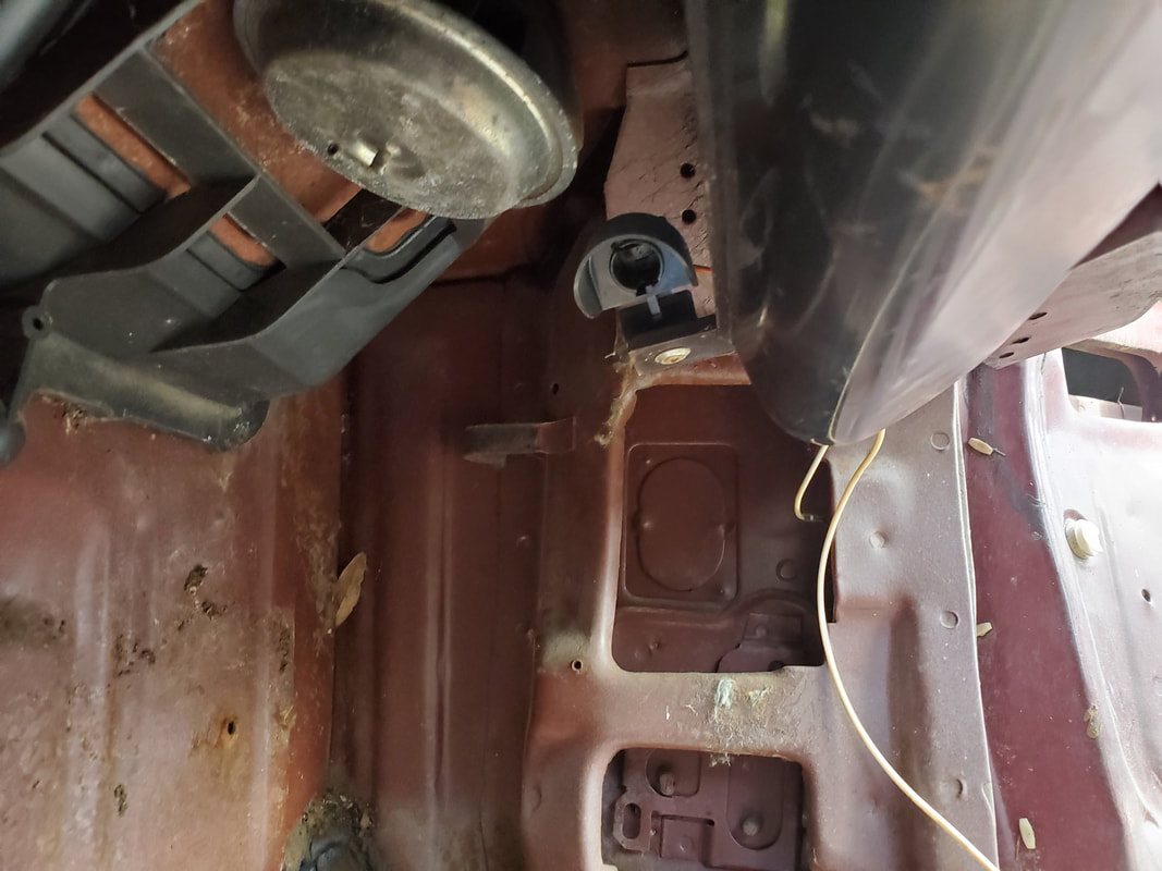 Passenger side under dash light fixture installed and wired up. The next task was the turn signal. Even though I already ran all the wires for the whole circuit, and hooking everything up to their respective points, there was still the matter of the SPDT switch I would have to install on the steering column. The first thing I had to do was find something with which to mount the switch against the steering column. I came up with using a wood framing bracket I had laying in a pile with other surplus. After mapping out how I would have to trim the metal piece to make it fit neatly enough that it doesn't look too tacky, I still had to rip out the old turn signal cam assembly. I had to cut this piece out to get it fully free of the steering column. The old wiring came out as well. 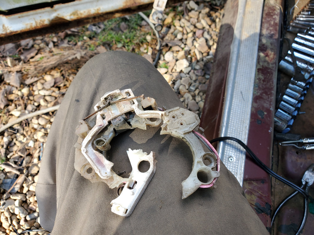 Old turn signal cam removed from steering column. 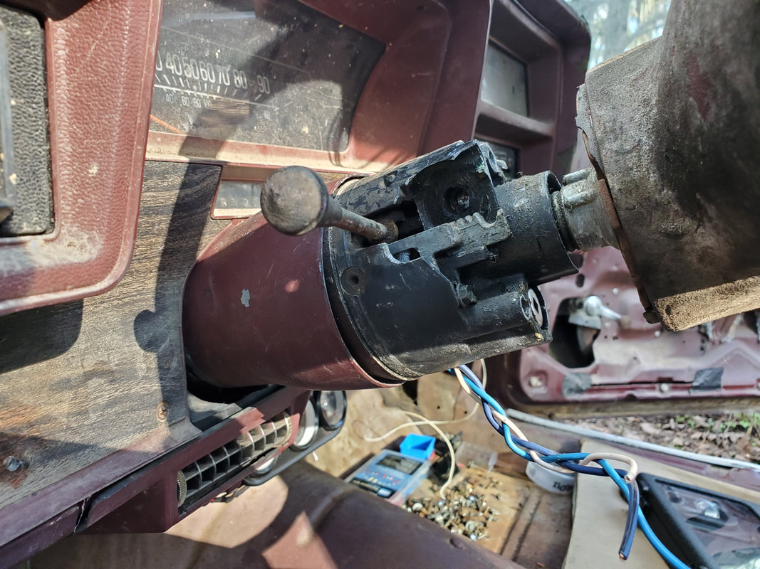 Steering column neatened up after removing the old turn signal assembly. Using one bolt point on the steering column and drilling a small hole on the side, I was able to install the metal piece, after modifying it. Using a step bit, I was able to drill the hole to hold the switch while a regular drill took care of the small hole, I needed for the other point of connection on the metal piece. A self-tapping screw would go into the side of the steering column to cut the thread in the hole. 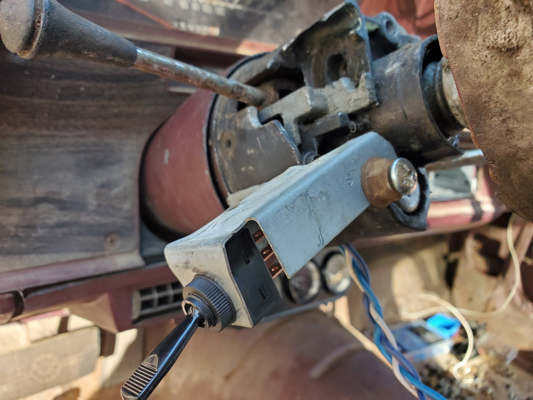 SPDT switch installed in modified metal brace. note how brace is attached to side of steering column. 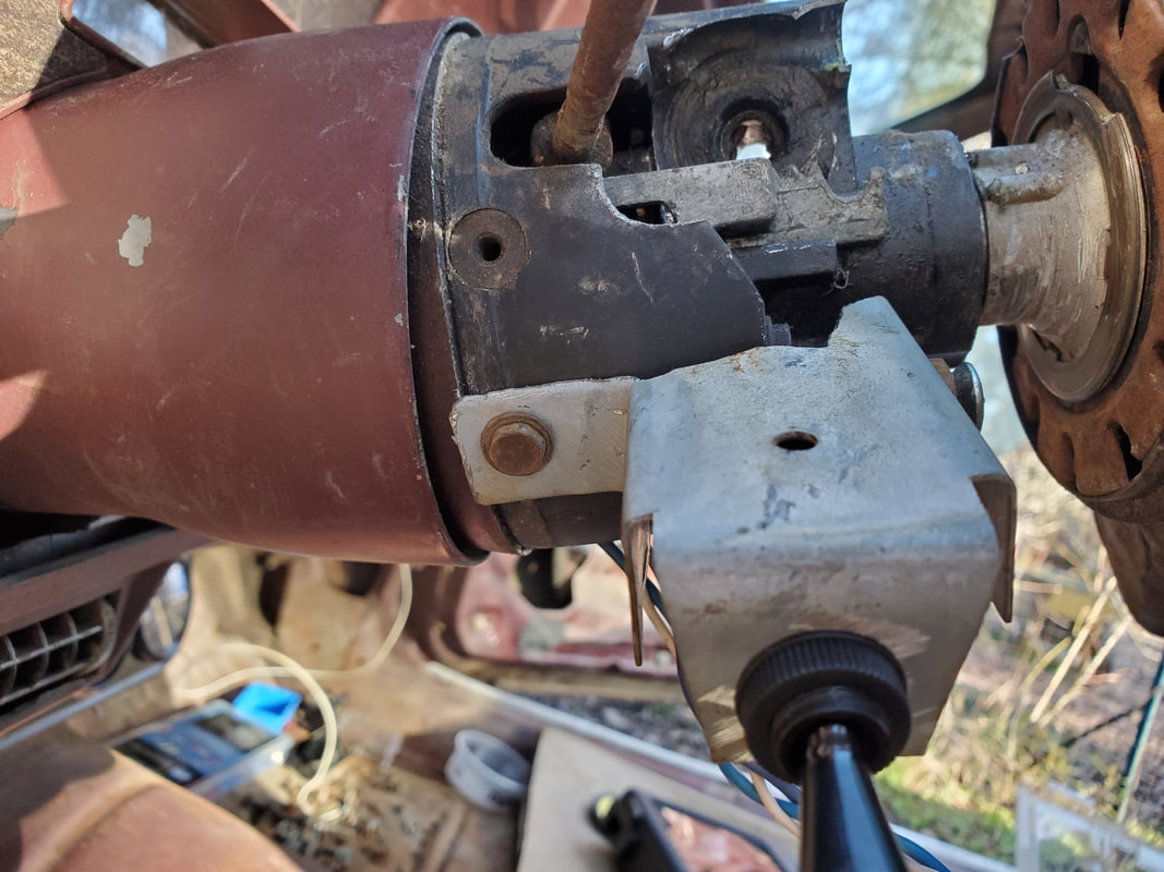 Extra screw hole on the side of column with self-tapping screw in place. 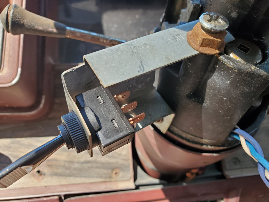 Underside shot showing how switch is in place relative to the wires and the rest of the steering column. 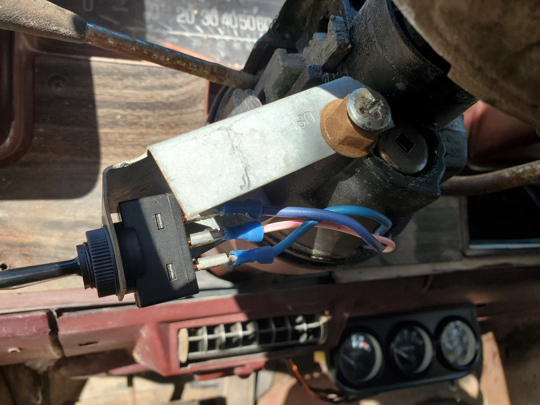 Switch in place with wires attached for the turn signal circuit. The last thing that I did for the day was install the speakers. This car had three speakers, one in the front, 2 in the back. The old back speakers were small and on special mounts that secured them in place where the molding could be secured over these speakers. I would have to find similar sized speakers to be able to replicate this. In the meantime, I took a couple of speakers that came from a late model Ford Ranger at the junkyard. These speakers are on frames that I was able to easily modify to mount to the back panel, behind where each seat would go. The magnets on the speakers are holding them up while two out of the four mounting tabs are utilized to hold the speakers to the back panel. 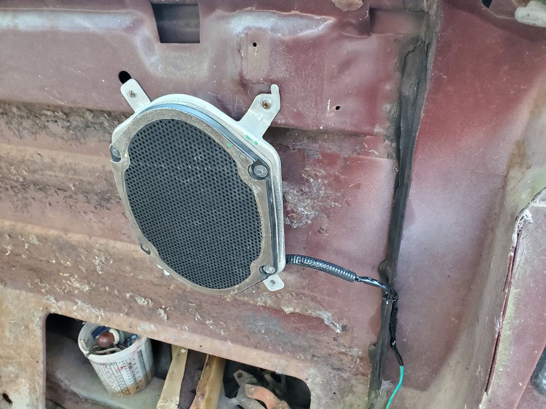 Driver's side speaker mounted in place. Note how two of the tabs are used to hold the speaker up via drilled holes on the raised portion of the back panel. 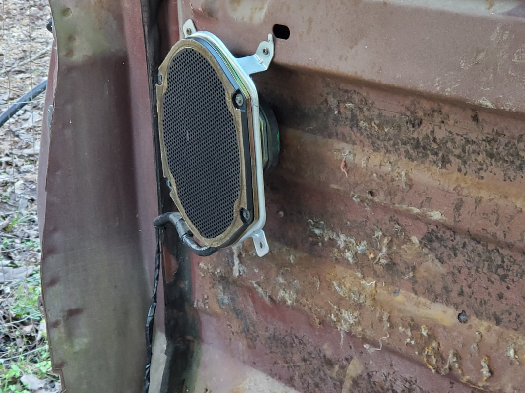 The same applies to the passenger side speaker. With the speakers mounted the next move was wiring them up. This involved a couple lengths of two conductor cable that was soldered to the ends of the wires on the speakers. These cables were routed down the corners of the rear of the cab and along the inner rocker panel along the floor. On the driver's side I was able to zip tie the cables to the factory cable that contains the wiring for the taillights. On the passenger side the cable will have to be secured some other way. Both pairs of cables are routed up and under the dash with both routed along with the existing wiring, terminating at the radio mounting hole. When we do install a radio these speaker wires will be ready to immediately hook up to the radio wire harness. 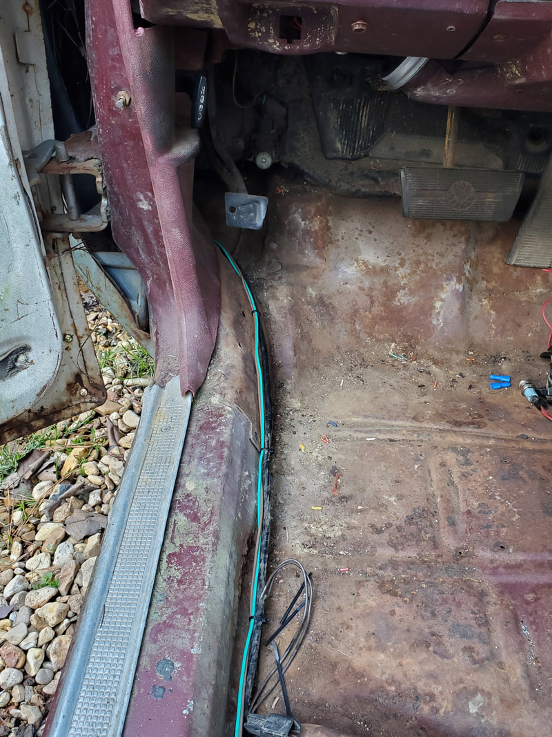 Green wires are the speaker wire pair routed along with the taillight wire bundle along the floor up to the dash, secured with zip ties. 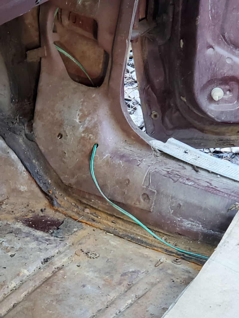 On the passenger side the green wire pair is routed up along the side, taking advantage of holes in the inner body to route the wires up under the dash. The wires are routed along with the door switch/under dash light fixture over to the middle of the dash where the radio hole is. 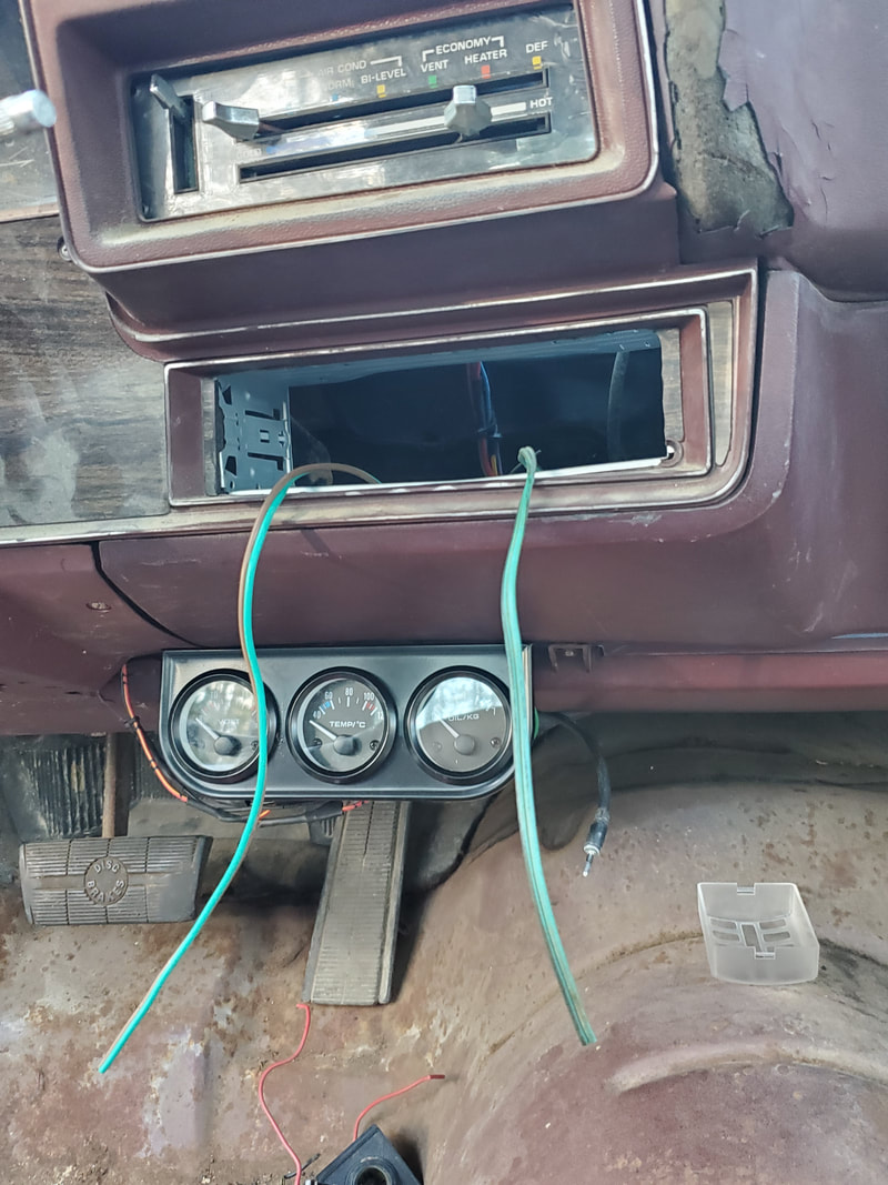 At the radio hole the two pairs of speaker wires are hanging out, on either side to designate which side each pair represents. Now for a radio... With all this done, my next move is to install a pair of 12v power receptacles. Even though there's one in the ash tray, it can't be disassembled to replace if need be. I have a couple of external plastic bodied 12v receptacles that are able to be mounted via two screws to any flat surface, in our case, under the dash, next to the aftermarket gauge cluster. These two receptacles will be routed over to an inline fuse terminal that splits into two wires to feed the two receptacles. I would've routed them to one of the other fuse terminals on the fuse block, but that would've made the terminals be switched power sources. I may want to power something without turning the car on, plus if I powered something of a high amperage, I don't want to compromise the car's wiring running something on either of the receptacles. After the 12v receptacles, I still need to wire in new taillight sockets to replace the boogered light sockets that are currently on the taillights. Once all this is done, I can put power on the car and start testing everything. As one can figure, wiring up a car is a tedious process, whether with a factory made wire harness or with a bundle of wires and zip ties and connectors. I am getting pretty far ahead on the work with the Elco rewiring. Some of the stuff that I need to do on the car involves buying a couple components here or there to finish the entire circuit, such as the turn signal, interior/dome light, or radio. I did have to install an aftermarket gauge cluster since the dash/gauge cluster was nothing more than some idiot lights and a defunct fuel gauge. That's another thing I have to buy to install, an aftermarket fuel gauge. But as for the aftermarket gauge cluster, I had to finish up with running the wires through the firewall to the engine to hook up later to the temp sensor and oil pressure sensors. 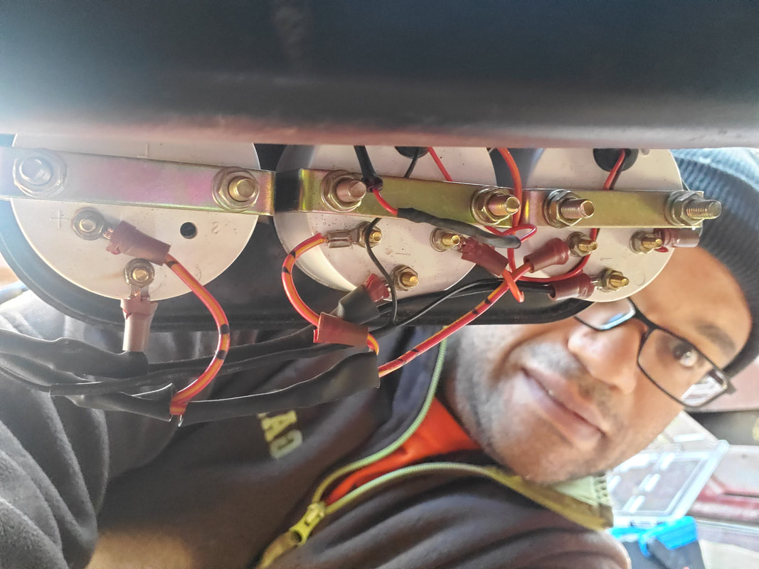 The rear of the gauge cluster with all wires hooked up, including the sensor wires going out to the engine. I won't be able to get the temp and oil sensors hooked up until I take care of some other parts of the build. One of those is the installation of the intake. Because the intake I have is for the older generation cylinder heads, I will have to get a pair of head gaskets and grab the cylinder heads (along with the accessories) from one of our older engines and swap those heads out with the newer heads that are currently on the engine. Once I get the intake on, I still have to add an adapter for the fitting in the oil port on the back of the engine that necks down from 1/4" NPT to 1/8" NPT since the sensor uses 1/8" NPT. Once that is all done I can hook up the sensor lines, concluding that part of the wire up. 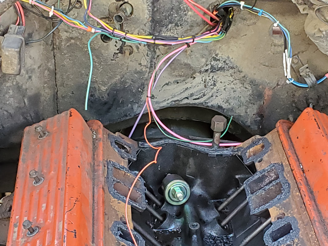 Wires run out to the engine, including the two sensor wires. The other wires are for the distributor and the starter solenoid. Note the oil pressure sensor sitting in the intake valley of the engine. After finishing up the gauge cluster I also took the time to route the wire for the fuel pump over to the fuse box. I already ran the wire from the fuel pump itself over to the engine bay and through the firewall. I had plenty of wire to feed into the cab and route along the wire harness path over to the fuse box so I can write that circuit of as well. Next on the list is the dome light/door light circuit. There are two switches that have both wires versus the later switches that are just switched grounds. To make things easy, I decided to wire the switches up as switched grounds. One wire on each switch was capped and secured to a bolt close by to serve as a ground. One wire from one switch will be routed over to the other switch and a wire will be routed from that switch up the A pillar over to the dome light. A power line will be routed from the dome light back down the A pillar over to the fuse box, thereby completing that circuit. 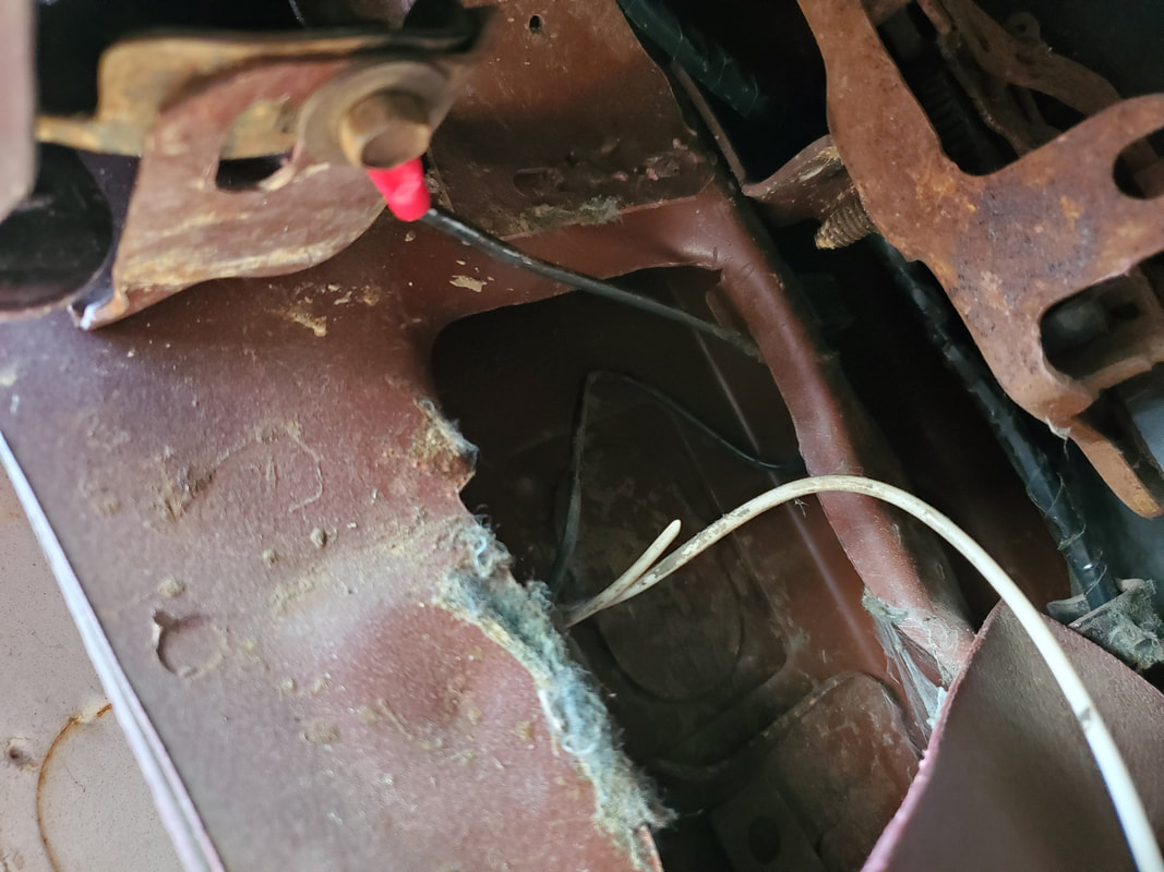 Wires from door switch. Black wire is hooked up to chassis ground and one white wire is cut due to be unnecessary. The other white wire will be hooked up to the other door switch white wire and an extra wire will be routed up to the dome light. While I was at it, after doing the ground for the driver's side door switch, I took the time to remount the interior panel, which also holds the hood release latch. While this has nothing to do with the electrical system, getting this panel mounted gets the piece out of the way and saves me one piece that I would've had to take care of later after I do finish with the electrical system. 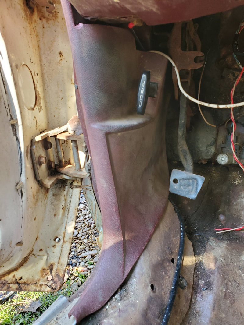 Interior panel installed over spot where door switch and wires are located. Note hood latch in panel. I plan on installing all the interior pieces after getting the electrical system done so I can eliminate these pieces from the pile of puzzle pieces. Of course I would need to get all the wiring done so I won't have to worry about removing and remounting wires. Once the wires are up the panels go up, the interior comes together that much more. One more thing I would have to do as far as wiring on the interior electrical system is the installation of speakers for the radio. The old speakers were mounted on the back, on either side of the back window. Wires for both speakers would have to be routed down the back corners of the cab down along the inner rocker panel and over to the dash to the radio. All the more reason the wiring needs to be done before the panels go up. 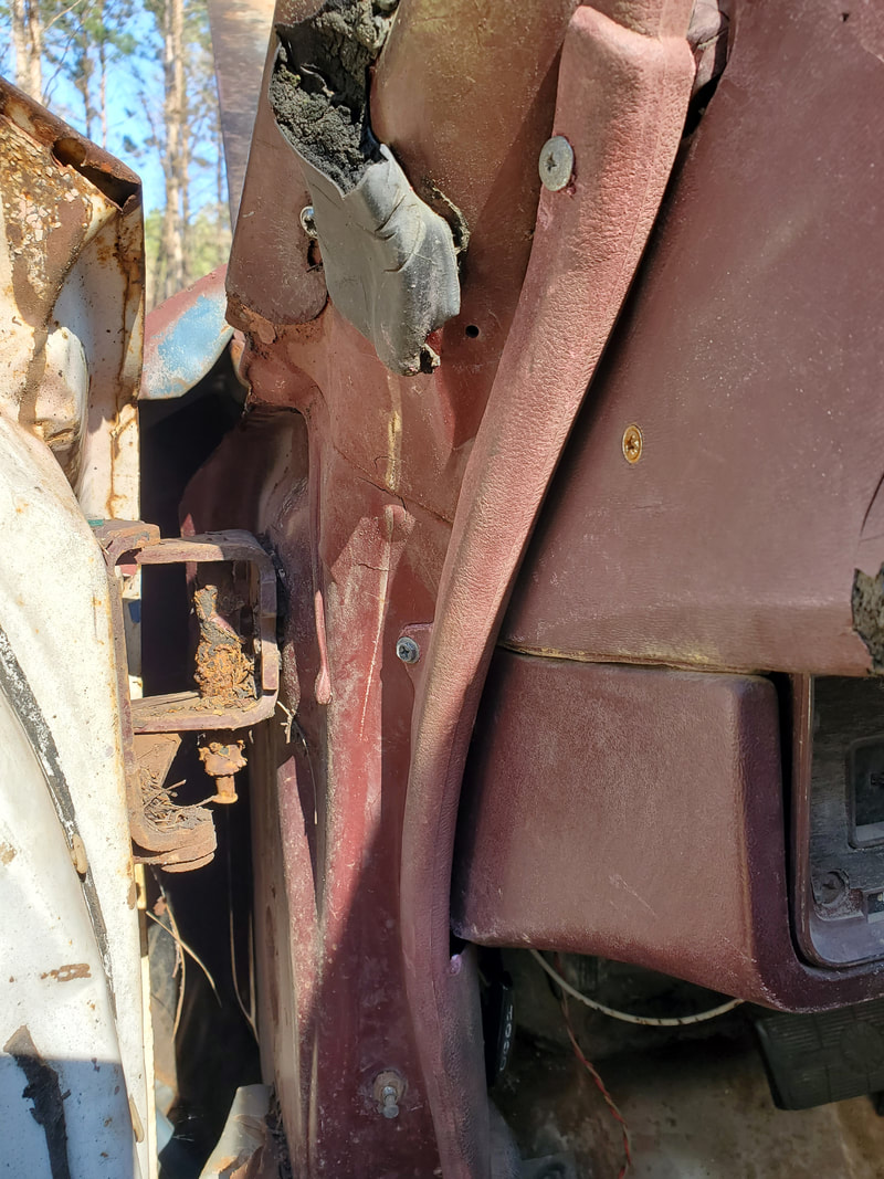 Extra screw added to extension of interior piece leading up to A pillar due to plastic being broken off that would've tucked the piece in snug. This will keep the plastic from flapping around in the door jamb area. Tacky, yes. Effective, yes. Along with the panels I will also want to paint the floors to get them covered and protected. More than likely I'll just use some Rustoleum paint like I did on the Dodge, otherwise I may splurge and get a can of bedliner and cover the floor with that. Really though I would rather just paint the floor in order to prep the floor for a carpet later on. Painting the floor will at least help preserve the metal inside until I can afford a carpet. Everything is definitely coming together. Taking a break from working on the Elco we took the time to focus on a couple other little things around the homestead that are a continuous process, at least until we finally complete them. These things are the spreading of gravel, which we've been doing for more than a year, and the erecting of the perimeter fence, also another year + project, mainly due to costs and the sheer size of the project. As usual we take the time to get a load of gravel every week and spread it out over a select area, with our current area being the garden. This current load as predicted, would be enough to cover the main walkways around the raised beds and fence lines in the southeast corner of the garden. In fact I had enough to cover the main walkways and start spreading gravel under the raised beds, which will be the next phase of covering the garden. 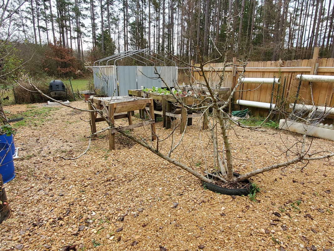 Greater area around raised beds at the back of the garden that's covered with gravel. Unlike the regular spreading of the gravel where I just dump the wheelbarrow on the ground and spread it out, I'll have to use a shovel to scoop and spread the gravel from the wheelbarrow to the spots under each raised bed to ensure proper coverage of all bare surfaces. I'm optimistic that this part won't take much to finish and once finished, I can move on to another area of the compound that I want to finish covering, like the rest of the back area leading up to the firewood staging area. 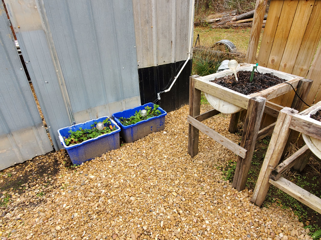 Walkways around raised beds leading up to greenhouse building that are now covered with gravel up to the fence line. This area will take some loads to fully cover as it is a wide as well as long area. This area does coincide with the next task that we're working on which is erecting fence panels. The last place we left off was at the northeast corner, by the firewood staging area. Erecting the fence along the eastern fence line is our current objective. The main goal is to get the panels up along this section of the eastern fence, up to the east gate that opens the eastern end of the midway to the greater yard. 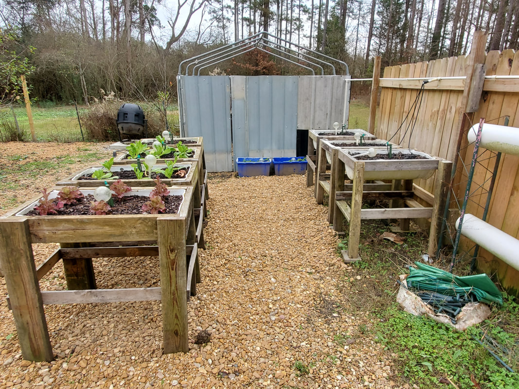 Pathway covered with gravel with some areas under the raised beds also covered. Note bare spot along fence line where a fledgling hydroponic garden assembly sits. That area will need to be covered. Closing in this area and section of the yard will put us in a position where it will be easier to contain movement of the animals as we have some crazy dogs that need to be able to be contained without being contained. Closing in this section of the yard will allow us to let the dogs run loose without worrying about them moving further out into the greater yard and into the surrounding woods. Of course, we'll still have to get fence pickets to tack up to the gates to cover that part. Once that's done then the northeastern quadrant of the compound will be contained as the old garden fences are still up and will effectively contain these areas. 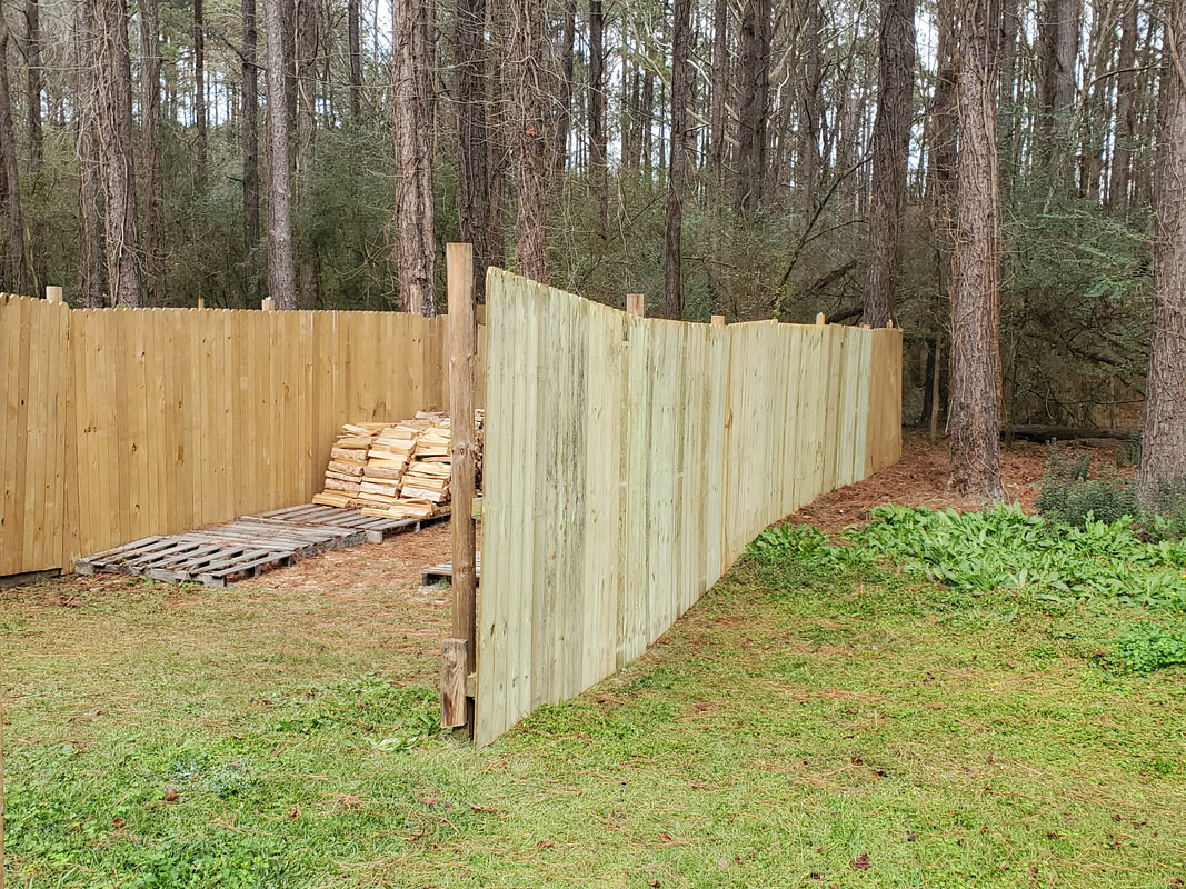 Fence panels hung up on the eastern fence line to close things in. 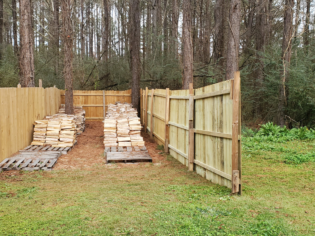 Fence panels hung in place, covering the firewood staging area from any view from the outside. At this point we managed to hang up three fence panels, effectively closing in the firewood staging area in its current stage. As I cut and split more firewood I may have to add more pallets to expand the rows of stacked wood. Now at this point we have four more positions left to close in that section of the eastern fence. We managed to get lucky a couple of times, being able to get fence panels that were damaged and getting a 10% discount because of it. The damage is typically a broken picket, which I fixed both times by just tacking the damaged picket back in place. As has been the case on other panels, I've also had to add more boards to the posts due to variations in spacing when I initially sunk the posts. Seems like no matter how much effort is taken to ensure proper spacing some panels will end up being off by a couple of inches. 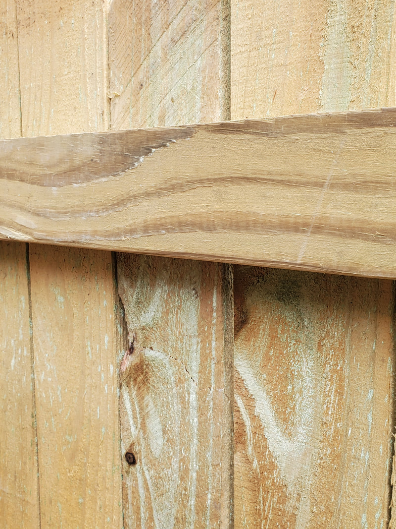 The cracked/damaged picket that was not on the panel when we picked up this unit, prompting a discount. 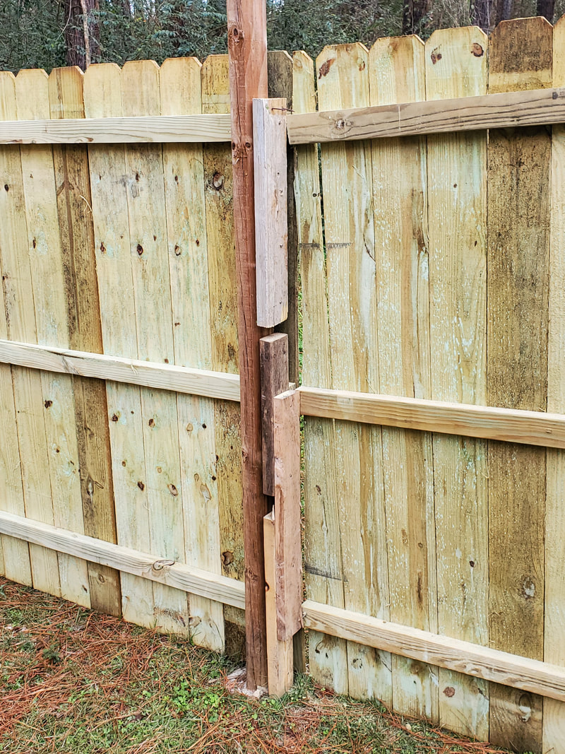 Extra boards added to fence post to provide the extra surface that will allow for the ends of the fence panel to be nailed in place. Also note how the end of the panel had to be trimmed to take into account the angle of the ground as it changes. Last thing on the menu is an issue that suddenly popped up on the Tracker. After taking the vehicle to a shop for a front end alignment (which we're unable to do as of yet due to lack of tooling), shortly after the ole lady left the thing started bucking and running shitty. At first I thought it was a problem with the O2 sensor plug for the upstream sensor (which isn't quite right and will flake out). After reseating the plugs and securing the thing with a zip tie so that it can't loosen up I took the truck out for my daily drive to the job and once I started getting up to near highway speed the truck started bucking again, with the engine light flashing. I kept my scanner in the vehicle so I was able to test it on the fly. It kicked back a cylinder 3 misfire fault. I figured that it was probably the coil pack for that plug. Luckily I still had three coil packs salvaged from the dead engine that was originally in this truck so when I went to change the coil, I pulled the plug, only to find that it was missing the whole ceramic core and electrode. That would definitely explain the cylinder misfire. Obviously it wasn't the coil, but the plug. For once the typical suggestion of replacing the spark plugs because of a cylinder misfire fault was actually true. Also luckily I saved the cylinder head from that old engine, which still had the plugs in it so this quick fix was able to be conducted to bring the Tracker back to full operational status. 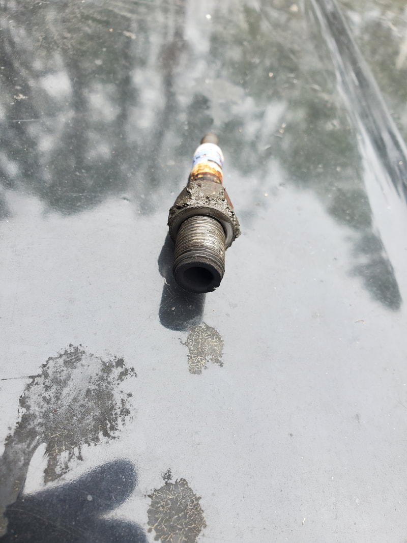 The culprit spark plug from the Tracker that is missing the ceramic core. Now one might ask, "what about that ceramic core and metal electrode?" That's a real good question. I would have to guess that this material may have been pulverized and spit out through the exhaust valve at some point, or may have been embedded in the cylinder. I don't hear anything that would be indicative of material bouncing around in the combustion chamber like a little marble nor is there any oil burning/blow by that would be indicative of damage to the cylinder wall. Hopefully all will be well enough that the engine will continue to function like normal. One thing I will be doing is replacing the other plugs as these are prone to suddenly dying just the same and if that did happen, I might not be so lucky next time.
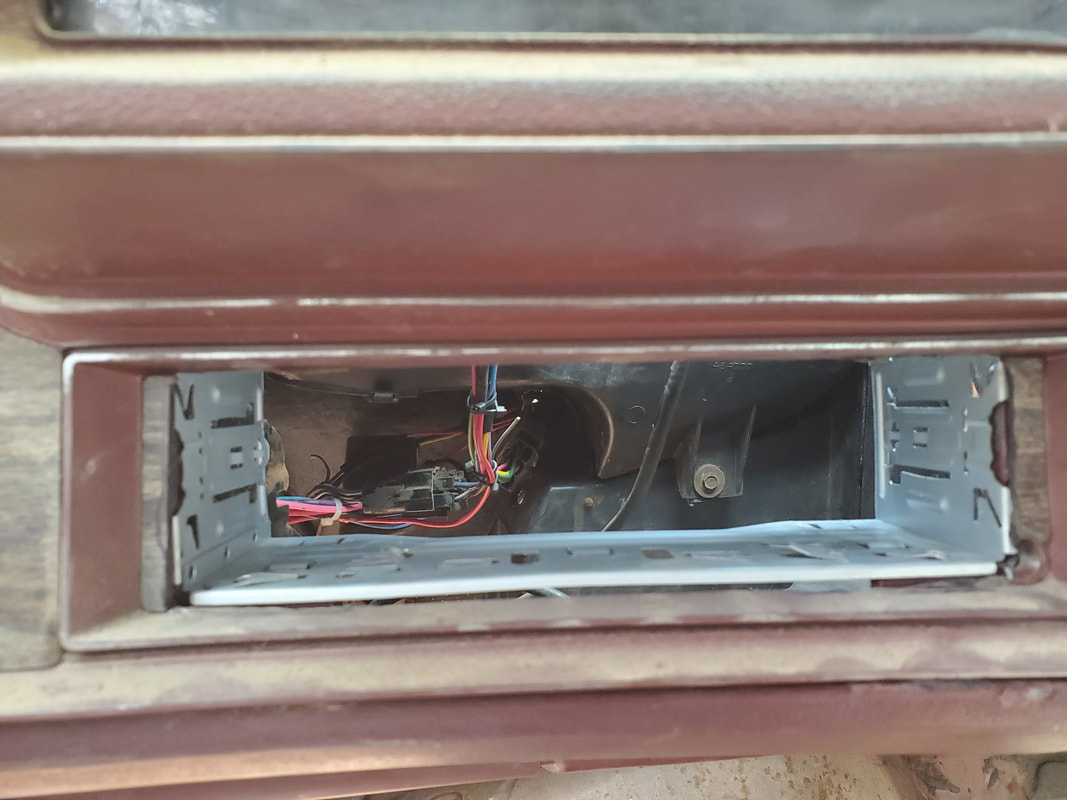
With the HVAC system rewired and working more or less I turned my attention to a couple other interior items that play into the rewiring. Those are the aftermarket gauge cluster and the radio mount. Along with that is the dash/gauge trim panel. The biggest thing is the gauge cluster since it will incorporate several sets of wiring for the gauge lights, the power and grounds to all three gauges and the outputs to the sensors on the engine. The easiest would be the radio mount since it's just a metal frame that needs a hole to be mounted in. I'll turn my attention to the radio mount.
Since the old radio was a more car specific unit, the dash had holes cut for the knobs and the display on the old radio. I would have to cut out this extra plastic so I could be left with a rectangular hole that will accommodate the single DIN radio mount. My battery rotary tool was able to tackle this little job and open things up for me. 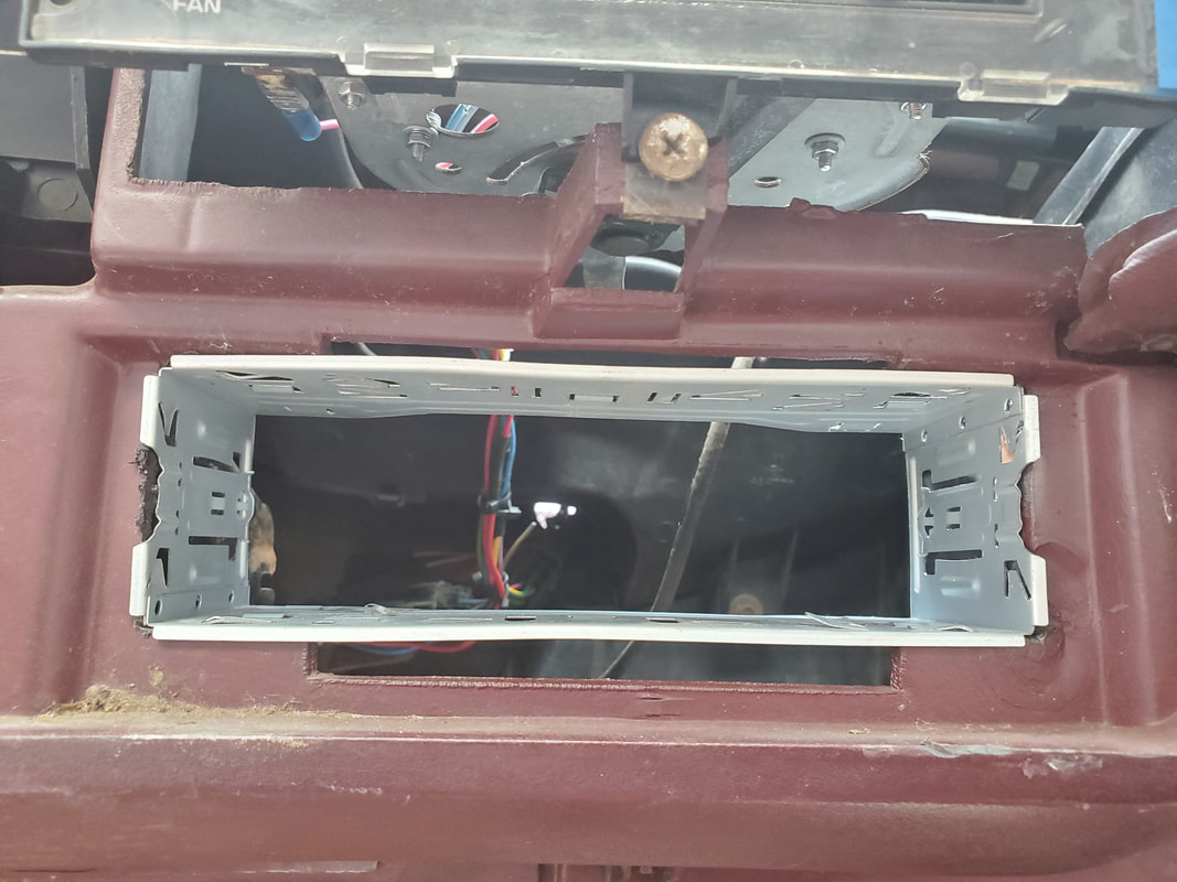
Hole in dash for old radio cut out to accommodate the single DIN radio mount.
With the radio mount in place the next thing I did was a little side task which was remounting the bottom vent ductwork that connects to the HVAC system and feeds from the chest level vent opening. Even though this isn't electrical per se, it was something that I could address quickly enough that I decided to do it and get it out of the way. There was only one other piece of the ductwork that needed to go back up so I got that installed pretty fast. At the same time, I had to block off the ends of the ductwork on both sides since there would be no side vents to feed from the chest level vent. To do this the only thing I could find on the fly in the storage trailer was a couple of large mason jar lids and rings. I used the hot glue gun to attach these to the ends of the ductwork on both sides of the lower end. 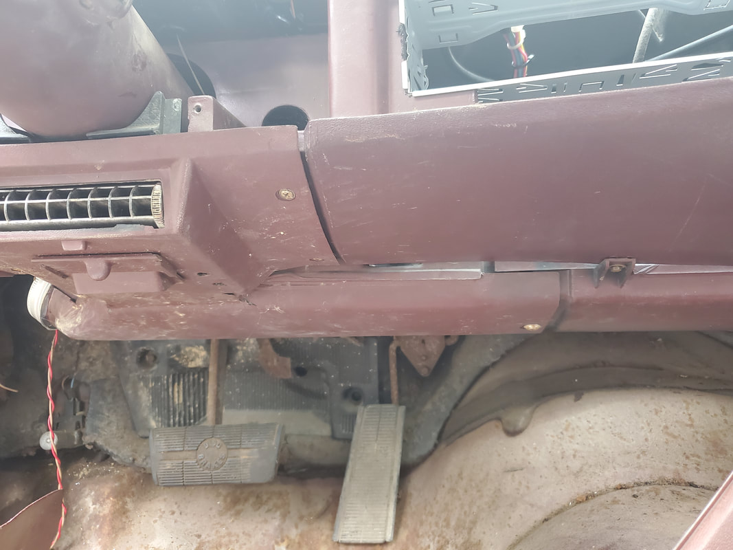
Driver's side ductwork installed. The passenger side ductwork was already installed so the driver's side was the only one needed.
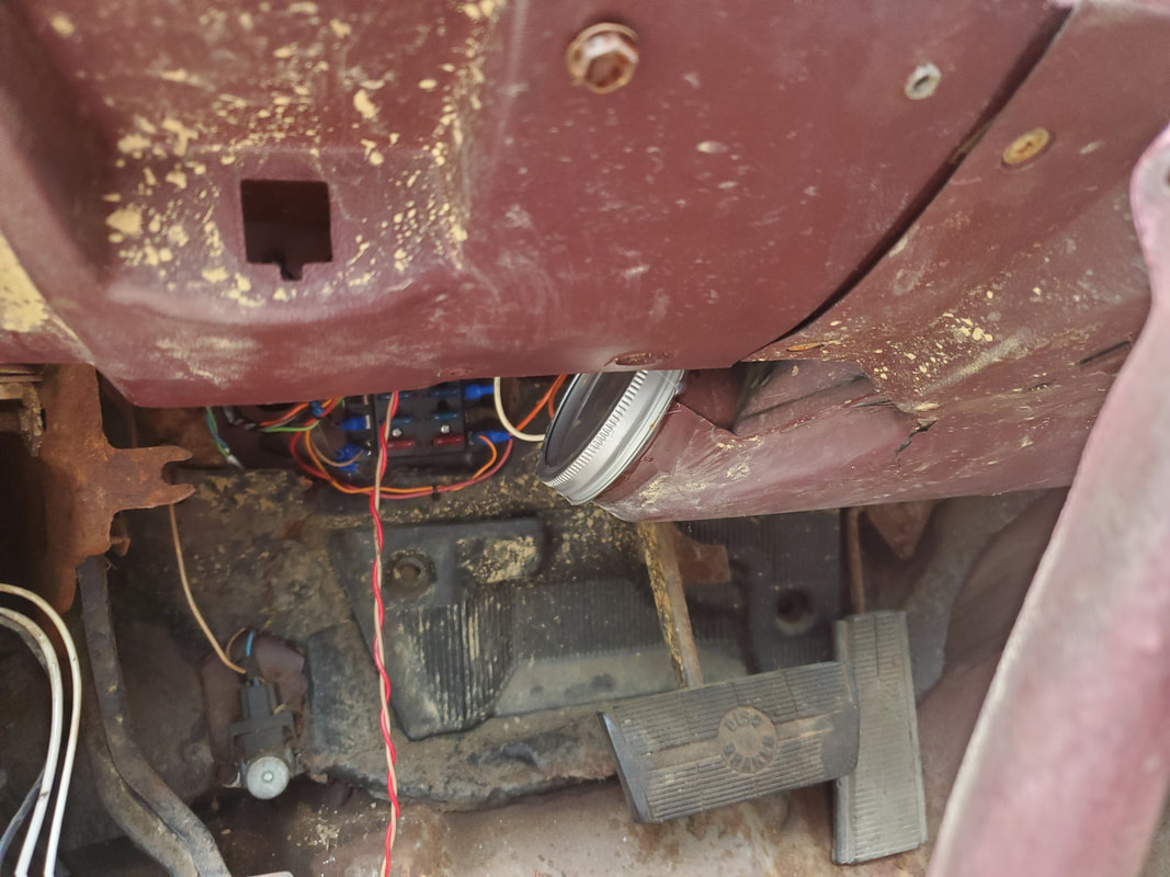
Driver's side lower vent with mason jar lid and ring glued in place to cap it off.
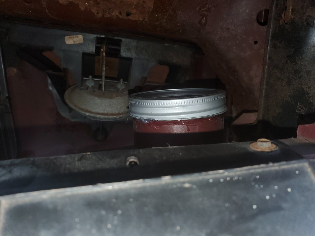
Passenger side duct with lid cap in place.
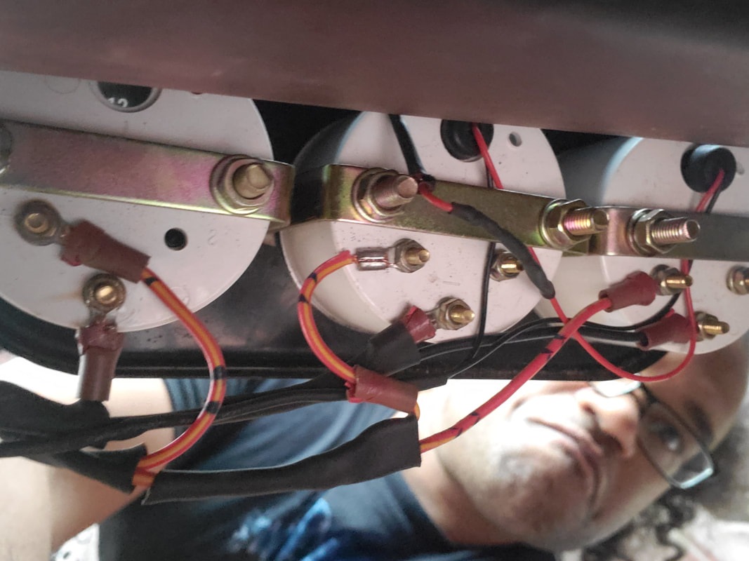
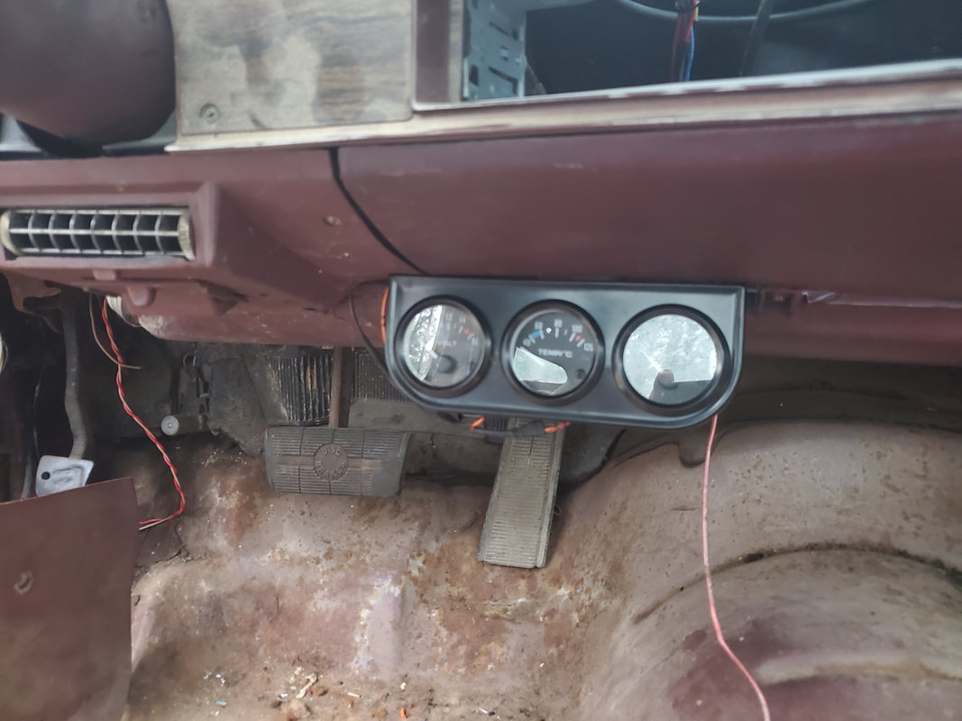
With the ductwork and radio mount addressed I went ahead and put the gauge/dash trim cluster back in place. Before I could do this I still had to trim out the plastic from around the radio face area to create another rectangular opening so when the radio is put in, things will look cleaner. 
Dash/gauge trim panel installed back on the front of the dash.
Closeup of the radio mount area showing the carved away front of the trim panel.
Now I can actually get to the aftermarket gauge cluster. First thing I wanted to do was get most of the wiring done on the gauge set before hanging everything since reaching behind the assembly would be difficult. I wired up the gauge lights together with the intent of running just one wire to the headlight circuit. From there I also ran the grounds and the positive wires from the three gauges. The voltmeter is the only gauge without a sensor line. With the power wires from the gauge lights run to the wire coming from the headlight switch and the grounds spliced together to be connected to the same bolt on the fuse box panel, I got ready to mount the gauge cluster. 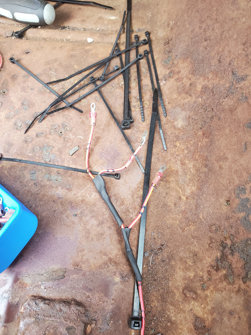
Power wires spliced together for the positive terminals on the three gauges.
Back of gauge cluster with power lines and gauge lights wired up.
As usual I routed the new wires along the same paths that the other circuits' wires are taking, securing everything with zip ties to keep the wiring nice and neat. The only wires left to run to the gauge cluster are the sensor wires, with just two to count. The voltmeter just reads the voltage on the circuit it's hooked up to, making our power output easy compared to an ammeter, which needs to be hooked in series with the car's electrical system where it comes from the alternator and battery at the same time. Knowing how most cars work, reading the voltage says a lot of the charging system since a working charging system will have the voltage up to 14v or more and below 13 means the car's running off of the slowly dying battery. Anyway, it's just the temp gauge and oil pressure gauge that need wires run from them out to the engine. I will have to add adapter fittings to the holes on the intake and on the fitting on the back of the engine to accommodate the temp sensor (intake) and the oil pressure sensor (back of engine). There really isn't too much left of the electrical system now.
|
